TIMER - AN0014 - Application Note - Energy Micro
TIMER - AN0014 - Application Note - Energy Micro
TIMER - AN0014 - Application Note - Energy Micro

Create successful ePaper yourself
Turn your PDF publications into a flip-book with our unique Google optimized e-Paper software.
...the world's most energy friendly microcontrollers<br />
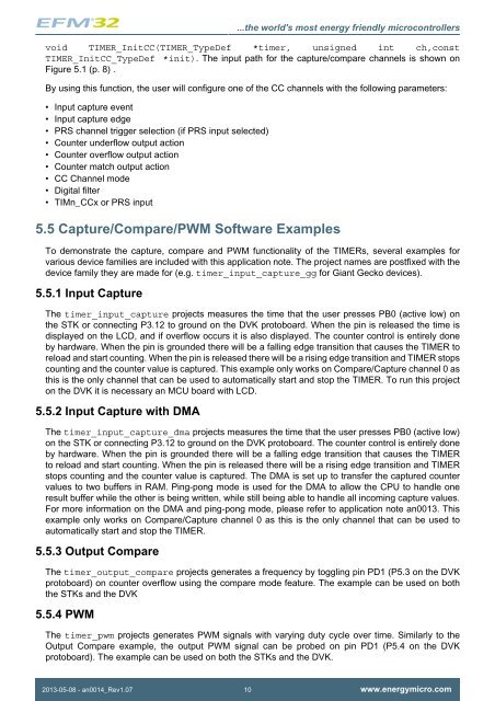
void <strong>TIMER</strong>_InitCC(<strong>TIMER</strong>_TypeDef *timer, unsigned int ch,const<br />
<strong>TIMER</strong>_InitCC_TypeDef *init). The input path for the capture/compare channels is shown on<br />
Figure 5.1 (p. 8) .<br />
By using this function, the user will configure one of the CC channels with the following parameters:<br />
• Input capture event<br />
• Input capture edge<br />
• PRS channel trigger selection (if PRS input selected)<br />
• Counter underflow output action<br />
• Counter overflow output action<br />
• Counter match output action<br />
• CC Channel mode<br />
• Digital filter<br />
• TIMn_CCx or PRS input<br />
5.5 Capture/Compare/PWM Software Examples<br />
To demonstrate the capture, compare and PWM functionality of the <strong>TIMER</strong>s, several examples for<br />
various device families are included with this application note. The project names are postfixed with the<br />
device family they are made for (e.g. timer_input_capture_gg for Giant Gecko devices).<br />
5.5.1 Input Capture<br />
The timer_input_capture projects measures the time that the user presses PB0 (active low) on<br />
the STK or connecting P3.12 to ground on the DVK protoboard. When the pin is released the time is<br />
displayed on the LCD, and if overflow occurs it is also displayed. The counter control is entirely done<br />
by hardware. When the pin is grounded there will be a falling edge transition that causes the <strong>TIMER</strong> to<br />
reload and start counting. When the pin is released there will be a rising edge transition and <strong>TIMER</strong> stops<br />
counting and the counter value is captured. This example only works on Compare/Capture channel 0 as<br />
this is the only channel that can be used to automatically start and stop the <strong>TIMER</strong>. To run this project<br />
on the DVK it is necessary an MCU board with LCD.<br />
5.5.2 Input Capture with DMA<br />
The timer_input_capture_dma projects measures the time that the user presses PB0 (active low)<br />
on the STK or connecting P3.12 to ground on the DVK protoboard. The counter control is entirely done<br />
by hardware. When the pin is grounded there will be a falling edge transition that causes the <strong>TIMER</strong><br />
to reload and start counting. When the pin is released there will be a rising edge transition and <strong>TIMER</strong><br />
stops counting and the counter value is captured. The DMA is set up to transfer the captured counter<br />
values to two buffers in RAM. Ping-pong mode is used for the DMA to allow the CPU to handle one<br />
result buffer while the other is being written, while still being able to handle all incoming capture values.<br />
For more information on the DMA and ping-pong mode, please refer to application note an0013. This<br />
example only works on Compare/Capture channel 0 as this is the only channel that can be used to<br />
automatically start and stop the <strong>TIMER</strong>.<br />
5.5.3 Output Compare<br />
The timer_output_compare projects generates a frequency by toggling pin PD1 (P5.3 on the DVK<br />
protoboard) on counter overflow using the compare mode feature. The example can be used on both<br />
the STKs and the DVK<br />
5.5.4 PWM<br />
The timer_pwm projects generates PWM signals with varying duty cycle over time. Similarly to the<br />
Output Compare example, the output PWM signal can be probed on pin PD1 (P5.4 on the DVK<br />
protoboard). The example can be used on both the STKs and the DVK.<br />
2013-05-08 - an0014_Rev1.07 10 www.energymicro.com