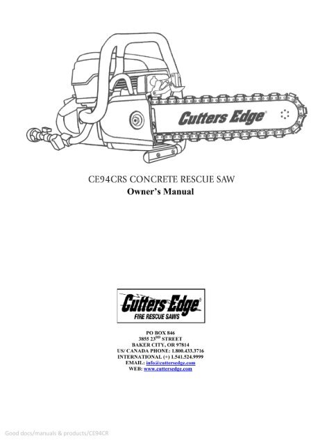
introduction - Cutters Edge
introduction - Cutters Edge
introduction - Cutters Edge
Create successful ePaper yourself
Turn your PDF publications into a flip-book with our unique Google optimized e-Paper software.
INTRODUCTION<br />
This manual outlines the maintenance and operation of <strong>Cutters</strong> <strong>Edge</strong> manufactured products.<br />
The CE94CRS concrete rescue saw is designed to cut concrete, stone, and masonry when used with the appropriate<br />
genuine diamond chain.<br />
To get the maximum benefit from your saw, and ensure maximum safety, be sure to read this manual thoroughly, and<br />
periodically review safety instructions.<br />
TABLE OF CONTENTS<br />
SYMBOLS & LABELS 2<br />
GENERAL SAFETY PRECAUTIONS 4<br />
TECHNICAL DATA 5<br />
SET-UP 6<br />
OPERATION 9<br />
MAINTENANCE 13<br />
TROUBLESHOOTING 19<br />
REFERENCE 20<br />
WARRANTY 21<br />
1
SYMBOLS & LABELS<br />
THE FOLLOWING SYMBOLS & DEFINITIONS ARE FOUND THROUGHOUT THIS MANUAL AND ARE<br />
DESIGNED TO MAKE YOU AWARE OF POTENTIAL HAZARDS OR UNSAFE PRACTICES.<br />
A potentially hazardous situation exists which, if not avoided, could result<br />
in death or serious injury.<br />
A potentially hazardous situation exists which, if not avoided may result in<br />
minor or moderate injury or property damage.<br />
A potential situation exists which, if not avoided, may result in<br />
product or property damage.<br />
THE FOLLOWING SYMBOLS & LABELS MAY BE FOUND IN THIS MANUAL OR ON THE SAW<br />
Read the operator’s manual carefully and understand the<br />
contents before you use this equipment.<br />
Always use:<br />
• Protective helmet<br />
• Ear Protection<br />
• Protective glasses or full face protection<br />
Wear hand protection<br />
2
A potentially hazardous situation exists which, if not avoided, could result<br />
in death or serious injury.<br />
Chain breakage can result in high-speed ejection of parts, which can result in death or serious<br />
injury to operators or bystanders. The items listed below are critical to minimizing the risk of<br />
chain breakage and injury.<br />
• DO NOT operate a concrete chain saw with a damaged, modified, broken, or missing side<br />
cover, bottom guard, or guard flap. The side cover, bottom guard, and guard flap provides<br />
protection against contact with moving parts, ejected debris, broken diamond chain,<br />
thrown water and concrete slurry.<br />
• DO NOT operate saw with loose, missing, damaged or improperly repaired parts.<br />
• DO NOT insert saw into a slot narrower than the chain segments. Rapid pushback might<br />
occur. Reference: Most diamond segments are .225 inches (5.72 mm) wide.<br />
• DO NOT use damaged, modified or improperly repaired chain.<br />
• DO NOT run saw upside-down. Concrete debris can fly back into the operator’s face.<br />
• DO NOT cut ductile iron pipe with the concrete chain saw. Segment loss or diamond chain<br />
breakage may occur.<br />
A potentially hazardous situation exists which, if not avoided may result in<br />
minor or moderate injury or property damage.<br />
• Always turn a concrete chain saw OFF when performing maintenance on the saw including<br />
chain tensioning.<br />
• Never use equipment that is not functioning properly.<br />
• Have the saw repaired only by qualified service personnel.<br />
• Turn engine OFF before refueling. Keep away from open flame. Always provide adequate<br />
ventilation when handling fuel. Move saw at least 10 feet (3 m) away from refueling area<br />
before starting.<br />
• Diamond chains require a minimum water pressure of 50 psi (3.5 Bar). Insufficient water<br />
supply may result in excessive wear to the chain, which can lead to loss of strength and<br />
chain breakage, and/or damage to the guidebar nose sprocket.<br />
• Never start saw unless the bar, chain and side cover are properly installed.<br />
3
GENERAL SAFETY PRECAUTIONS<br />
• Always wear protective clothing, including hard hat, eye protection, hearing protection,<br />
and gloves.<br />
• Avoid loose fitting clothing.<br />
• Perform safety checks before starting each day.<br />
• Always operate tool with solid footing and with both hands on the saw.<br />
• Remove or control slurry to prevent slippery conditions while cutting.<br />
• Be sure there are no obstructions (plumbing, electrical conduit, air ducts) and no<br />
unnecessary people present.<br />
• Set up a well-marked safety zone with a roped boundary and clear signs.<br />
• Provide adequate ventilation when working in an enclosed area. Breathing exhaust gases is<br />
dangerous.<br />
• To avoid electrocution, check for live electrical wiring near cutting area.<br />
A potential situation exists which, if not avoided, may result in product or<br />
property damage.<br />
Note: The concrete chain saw is equipped with a 2-cycle engine and must always be run using a mixture<br />
of gasoline and <strong>Cutters</strong> <strong>Edge</strong> 2-cycle engine oil, or other high quality 2-cycle oil that has been formulated<br />
for air cooled power equipment. It is important to accurately measure the amount of oil to be mixed to<br />
ensure that the correct mixture is obtained. When mixing small amounts of fuel, even small inaccuracies<br />
can drastically affect the ratio of the mixture.<br />
• This engine is designed to be operated on premium unleaded gasoline.<br />
• Use high quality, unleaded gasoline with a minimum octane rating of 90. If lower octane gasoline<br />
is used, engine temperature will increase which can result in a piston seizure and damage to the<br />
engine.<br />
• Fuel mixture: 100:1 <strong>Cutters</strong> <strong>Edge</strong> or 25:1 petroleum based oil – gasoline/oil mixture. Incorrect<br />
fuel mixture is the number one cause of piston seizure.<br />
• Use <strong>Cutters</strong> <strong>Edge</strong> brand 2-cycle engine oil, or other high quality 2-cycle oil that has been<br />
formulated for air cooled power equipment.<br />
• Never use 2-cycle oil formulated for water-cooled 2-cycle engines, such as outboard motor oil.<br />
• Never use motor oil intended for 4-stroke engines.<br />
ENGINE BREAK-IN<br />
• It is very important to break-in a new engine to “seat” all moving parts, especially the piston<br />
rings.<br />
• To break-in the engine, run one full tank of 100:1 fuel at idle, cycling the throttle every 5 to 10<br />
minutes to prevent loading.<br />
• Failure to break-in an engine may result in piston seizure.<br />
4
CE94CRS TECHNICAL DATA<br />
Engine Type<br />
2-stroke, Air Cooled<br />
Displacement<br />
5.7 cu-in (94 cc)<br />
Horsepower<br />
6.4 hp (4.8 kW) @ 9000 rpm<br />
Torque<br />
50.4 in-lbs (5.7 Nm) @ 7,200 rpm<br />
Engine Speed<br />
9,300 +/- 150 rpm (max)<br />
2,700 +/- 100 rpm (idle)<br />
Weight<br />
22.25 lbs (10.1 kg) powerhead only<br />
18 in (46 cm) length<br />
Dimensions<br />
14 in (36 cm) height<br />
13 in (33.02 cm) width<br />
Air Filter<br />
Water resistant polyester<br />
Carburetor<br />
Walbro RWJ-5A<br />
Starter<br />
Dust and water resistant<br />
Ignition<br />
Momentary contact on/off switch<br />
Clutch<br />
Centrifugal, three shoe, three spring<br />
Fuel Ratio<br />
100:1 <strong>Cutters</strong> <strong>Edge</strong> synthetic 2-cycle Oil<br />
Fuel Capacity<br />
0.26 gallon (1 liter)<br />
Water Supply<br />
Minimum 50 psi<br />
Water Flow<br />
Minimum 2.5 gpm<br />
Noise Level 106 dB(A) at 3 ft (1 m)<br />
Vibration Level<br />
3.9 m/s (front handle)<br />
4.1 m/s (rear handle)<br />
Engine Break-in Period<br />
One tank, without cutting, cycling throttle<br />
Spark Plug<br />
NGK BPMR7A OR Champion RCJ6Y<br />
Electrode gap 0.020 in (0.5 mm)<br />
12 inch (30.48 cm)<br />
Available Bar Lengths<br />
14 inch (35.56 cm)<br />
16 inch (40.64 cm)<br />
12 inch (30.48 cm)<br />
Cutting Depth for Each Length<br />
14 inch (35.56 cm)<br />
16 inch (40.64 cm)<br />
5
SET-UP<br />
GUIDEBAR AND DIAMOND CHAIN INSTALLATION<br />
STEP 1<br />
Loosen side cover nut and remove side cover.<br />
STEP 3<br />
Mount the diamond chain on the guidebar<br />
starting at the drive sprocket and continue over<br />
the guidebar nose.<br />
STEP 2<br />
Place bar onto stud and engage alignment block.<br />
STEP 4<br />
Install the side cover and ensure chain<br />
adjustment pin engages hole in bar. Do not fully<br />
tighten side cover nut until after chain is<br />
properly tensioned.<br />
6
STEP 5<br />
Make sure that all the drive links are inside the<br />
guidebar groove then lift the bar nose and<br />
tension the chain by turning the screw clockwise.<br />
STEP 6<br />
Before cutting, check for proper tension by<br />
pulling the chain around the bar by hand. If you<br />
cannot easily pull by hand, the chain is too tight<br />
and needs to be loosened slightly. CAUTION:<br />
Be aware that the guidebar rails may develop<br />
sharp edges over time so always pull the<br />
diamond chain by the diamond segments.<br />
7
STEP 7<br />
Continue to lift up on the nose of the guidebar<br />
and firmly tighten the side cover nut.<br />
NOTE: To prevent chain tensioner breakage, be<br />
sure the side cover nut is tightened to<br />
approximately 20-25 ft-lbs (27-33 Nm).<br />
STEP 8<br />
Attach to water source with pressure of not less<br />
than 50 psi (3.5 Bar).<br />
8
OPERATION<br />
FUEL HANDLING<br />
FUEL MIXTURE: 100:1 <strong>Cutters</strong> <strong>Edge</strong> synthetic 2-cycle oil gasoline/oil mixture.<br />
GASOLINE<br />
OIL<br />
GASOLINE<br />
OIL<br />
US Gallon<br />
US FL oz.<br />
Liters<br />
ml<br />
1 1.3<br />
2 1/2 3.2<br />
5 6.4<br />
1 10<br />
5 50<br />
10 100<br />
20 200<br />
• Use premium unleaded gasoline with a minimum octane rating of 90. If lower octane gasoline is<br />
used, engine temperature will increase which can result in a piston seizure and damage to the<br />
engine.<br />
• Always provide adequate ventilation when handling fuel.<br />
• Use caution when handling gasoline. Avoid direct contact with skin or inhaling fuel vapor.<br />
FUEL MIXING<br />
• Always mix gasoline and oil in a clean container intended for use with fuel.<br />
• Keep fuel container closed tightly to prevent moisture from getting into the fuel.<br />
• Always begin mixing fuel by adding half the amount of gasoline to be used. Then add the correct<br />
amount of 2-cycle oil for 100:1 (1%) mixture and finish filling the container with gasoline.<br />
• Do not mix more than one month’s supply of fuel. This helps prevent the separation of the 2-cycle<br />
oil from the gasoline (varnishing).<br />
• If the saw is not used for an extended period of time (3 months) the fuel tank should be emptied<br />
and cleaned.<br />
FUELING<br />
• Always shut off the saw before fueling.<br />
• Before fueling, clean the area around the fuel cap to prevent dirt from contaminating the fuel.<br />
Contamination of the fuel tank can lead to saw malfunction.<br />
• Thoroughly mix the fuel in its container before fueling.<br />
• Slowly open the fuel cap to release any pressure that may have built up in the tank.<br />
• After adding fuel, tighten the fuel cap carefully and secure with a wrench.<br />
9
STARTING AND STOPPING A CONCRETE CHAIN SAW<br />
Never start a concrete chain saw without the bar, chain and side cover<br />
properly assembled. Failure to do so may result in serious injury.<br />
Always move a concrete chain saw at least 10 feet (3 m) away from fueling<br />
area before starting.<br />
Place the saw on clear ground. Ensure that secure footing is established and<br />
chain is not contacting any objects.<br />
COLD ENGINE STARTING PROCEDURE<br />
1. Pull the choke lever out, which also sets the throttle lock.<br />
2. Depress primer bulb approximately 5-10 times.<br />
3. Push in decompression valve.<br />
4. Open the water valve ¼ turn.<br />
5. Place the saw on stable ground making sure the chain is free of any obstructions.<br />
6. Place foot on the base of the rear handle, and place one hand on front handle.<br />
7. With opposite hand, slowly pull starter handle until the starter pawls engage.<br />
8. Pull the starter cord (hard, fast, short pulls) until engine initially fires or “pops”. Could be as many<br />
as 10-15 pulls.<br />
9. Push the choke lever in.<br />
10. Pull the starter cord until engine starts – should be 1 to 2 pulls.<br />
11. Release the throttle lock by momentarily squeezing on the throttle trigger.<br />
12. When the engine starts, allow the engine to idle briefly. Squeeze the throttle trigger several times<br />
to help warm up the engine.<br />
13. Open the water valve completely.<br />
WARM ENGINE STARTING PROCEDURE<br />
1. Use the same procedure as starting a cold engine, but pull choke lever out, and then push back in<br />
to set the throttle lock. If choke is used on a warm engine, the carburetor will flood with gas.<br />
2. If the engine does not start in 3 hard, fast pulls with the throttle locked, fully squeeze and hold the<br />
trigger while pulling the starter cord 3 more times.<br />
NOTE: To hold the trigger fully open it may be necessary to insert right foot into rear handle<br />
opening and twist.<br />
STOPPING THE SAW<br />
• To turn the engine off, push stop switch to the ‘STOP’ position. Close water valve.<br />
10
PRE-CUT CHECKLIST<br />
• Ensure proper chain tension: The chain should be easily pulled around the guidebar by hand.<br />
• Ensure all safety devices are properly mounted and functional and that all controls are in proper<br />
working order.<br />
• Be sure there are no obstructions (plumbing, electrical conduit, air ducts) and no unnecessary<br />
people present.<br />
• Always wear protective clothing, including hard hat, eye protection, hearing protection, non-slip<br />
safety boots, and gloves. Avoid wearing loose clothing.<br />
• Adequate water supply and pressure:<br />
Minimum flow: 2.5 gpm (9.5 lpm)<br />
Minimum water pressure: 50 psi (3.5 bar)<br />
• Diamond chains require a minimum water pressure of 50 psi (3.5 bar).<br />
The single most important factor an operator can control to increase chain<br />
life is to use adequate water pressure. Insufficient water supply will result in<br />
excessive wear to the chain, which can lead to loss of strength and chain<br />
breakage, and/or damage to the guidebar nose sprocket.<br />
PLANNING THE CUT<br />
• Select the proper chain type for the material being cut.<br />
• Outline the cut with a permanent marker for visual cutting guide.<br />
• Avoid pinching the guidebar and chain. Always cut the bottom of an opening first, then top, and<br />
then the sides. Save the easiest cut for last.<br />
• For the straightest cuts use the “Step Cut” method. First score the entire cut line approximately a<br />
half-inch deep using the nose of the bar. Next, deepen the cut by about two inches. Then plunge<br />
all the way through and complete the cut using the Wall Walker.<br />
• Be sure cut concrete cannot fall and injure operator or bystanders. Concrete is very heavy, one<br />
cubic foot = 12 in x 12 in x 12 in = 150 lbs (30 cm x 30 cm x 30 cm = 68 kg).<br />
• Check for and remove any obstructions (plumbing, electrical conduit, air ducts, etc,) that may<br />
interfere with the cut.<br />
CUTTING WITH THE CE94CRS<br />
To start a cut, hold trigger on full throttle and slowly plunge the nose of the bar straight into the wall.<br />
Lengthen the cut and engage the point of the Wall Walker.<br />
11
CUTTING TIPS<br />
• Always operate the concrete chain saw at full throttle. If too much force is applied, the saw will<br />
lug or stall. The chain will not have enough speed to cut effectively. If too little feed force is<br />
applied, the diamonds will skid and glaze over.<br />
• For straighter cuts use the “Step Cut” method. First score the entire cut line with the nose of the<br />
guidebar approximately ½ in (12 mm) to 1 in (25 mm) deep. Next, deepen the cut by about 2 in<br />
(50 mm). This groove will help guide the guidebar for a straight cut. Then plunge all the way<br />
through and complete the cut using the Wall Walker.<br />
• Plunge cut instead of starting at the top surface of the wall. This will reduce chatter, extend<br />
diamond life, create a straighter cut and more quickly enable the use of the Wall Walker.<br />
USING THE WALLWALKER®<br />
The Wallwalker® is a high efficiency device designed to create a mechanical<br />
advantage and feed force. As the operator pushes the saw forward into the<br />
material being cut, the upward pivoting action of the Wallwalker® forces the saw<br />
downward creating a mechanical advantage. Use the Wallwalker® to cut<br />
efficiently and reduce fatigue.<br />
The Wallwalker® is a lever system that converts forward force to downward<br />
force and will develop a 4-to-1 mechanical advantage.<br />
• To use correctly, make the initial plunge cut and cut downward an inch or two to open the length of<br />
the cut to accept the Wallwalker®. Engage the point of the Wallwalker® into the cut and push<br />
straight in (forward), wedging the Wallwalker® point into the cut.<br />
• As you continue to push the saw forward into the cut, the Wallwalker® will begin to rotate up and<br />
feed force will develop downward along the line of the intended cut. While you are pushing the saw<br />
forward and the Wallwalker® is rotating up, the upward action of the Wallwalker® will begin to<br />
force the back handle of the saw down. Pull the back handle of the saw upward to counter the<br />
downward force and keep the saw perpendicular to the material being cut, otherwise the Wallwalker®<br />
point could skid and slip, which will reduce its effectiveness.<br />
• Once the Wallwalker® is fully rotated upwards, pull the saw out of the cut a few inches. The<br />
Wallwalker® point will snap back to its original position and you can re-engage the point of the<br />
Wallwalker® back into the cut and continue to cut and repeat.<br />
• When cutting heavy rebar, slowly “rock” the saw so that you’re always cutting concrete as well as<br />
steel. This will help keep the diamonds exposed. Also, expect less chain life when cutting heavy<br />
rebar.<br />
• Expect more chain stretch when making nose buried cuts for extended periods of time, as the<br />
chain does not have a chance to “throw” the slurry away from the nose of the bar.<br />
• If the saw begins to cut consistently crooked, turn the bar over and use the other side. Dress worn<br />
rails with belt sander. NOTE: The normal life of a guidebar is two to three diamond chains.<br />
Heavy rebar can shorten guidebar life.<br />
• Remove bar and chain. Flush out the chain tensioner and side cover with water. Lubricate<br />
tensioner with grease.<br />
• After cleaning the saw, spray the entire saw body, chain, bar, and drive sprocket with lightweight<br />
oil. Using silicone spray or WD40 on the saw will minimize rust and help reduce slurry build up.<br />
12
SYSTEM CLEAN-UP<br />
• After cutting, run the saw for at least 15 seconds with the water on to flush slurry and debris from<br />
chain, bar and drive sprocket.<br />
• Wash concrete slurry from saw assembly.<br />
• Avoid getting any water in the carburetor or exhaust system. If water enters exhaust port, point<br />
the bar tip down and pull the starter handle several times to expel water from muffler.<br />
MAINTENANCE<br />
Follow these simple maintenance guidelines<br />
and your saw will continue running at its very best.<br />
AFTER EACH USE<br />
1. Rinse the saw, guidebar and diamond chain with water.<br />
2. Inspect and tighten all fasteners as necessary.<br />
3. Inspect, flush and grease the chain tensioner.<br />
4. Inspect drive sprocket for wear. Replace if tooth tips are pointed, or if groove cuts through top of<br />
tooth.<br />
5. Check clutch cup needle bearing for wear. Ensure clutch cup spins freely and without excessive<br />
play.<br />
6. Check starter cord for wear or damage. Replace as necessary.<br />
7. Inspect air filter. Replace filter if dirty.<br />
8. Spray saw, guidebar, and chain with silicone or WD40.<br />
9. Spray silicone or WD40 into the air intake slots on the starter housing to keep starter pawls from<br />
sticking.<br />
AFTER 10 HOURS OF USE<br />
1. Remove the starter cover and clean the flywheel fins and the starter pawls with a wire brush, and<br />
then grease the starter pawls.<br />
2. Remove the spark plug and clean with a wire brush. Check the electrode gap. The correct gap is<br />
0.020 inches (0.5 mm).<br />
3. Grease the clutch cup needle bearing.<br />
AFTER 40 HOURS OF USE<br />
1. Change the spark plug. Adjust the electrode to 0.020 inches (05. mm).<br />
2. Check the fuel filter located inside the fuel tank. Clean or replace if clogged.<br />
13
AIR FILTER<br />
The polyester air filter must be kept clean for the engine to operate properly.<br />
If the saw is not reaching full RPM, most likely the air filter is dirty.<br />
• The air filter should be free of holes and<br />
white in color.<br />
• Replace air filter when dirty.<br />
• When replacing the air filter, clean the<br />
area inside the air intake housing with a<br />
clean rag prior to installing new filter.<br />
STARTER HOUSING ASSEMBLY<br />
It is common for concrete slurry to get inside the starter housing assembly<br />
during cutting. This can cause the starter pawls to stick and not engage<br />
when the rope is pulled.<br />
• After each usage, thoroughly flush the<br />
starter housing assembly with water.<br />
• Oil the starter pawls by spraying silicone<br />
or WD40 into the starter housing through<br />
the vents.<br />
• Check the starter cord for fraying,<br />
replace if necessary.<br />
14
STARTER ROPE REPLACEMENT<br />
• Loosen the four screws that attach the<br />
starter cover assembly to the crankcase,<br />
and remove the starter cover assembly<br />
from the saw.<br />
• Pull cord out from pulley approximately<br />
12 inches (30 cm) and hook rope into the<br />
notch in the pulley. Relax the recoil<br />
spring by placing thumb on the pulley<br />
and gently allow the pulley to rotate<br />
backwards to unwind the spring entirely.<br />
• Remove the old starter rope through the<br />
hole in the starter housing and then<br />
through the hole in the pulley.<br />
• Wrap the starter rope around the raised<br />
center of the pulley, looping over top and<br />
under the beginning of the wrap. Tighten<br />
the knot firmly and ensure that free end<br />
of rope is as short as possible. Secure the<br />
other end of the rope in the starter<br />
handle.<br />
TENSIONING THE RECOIL SPRING<br />
• Hook the rope in the notch of the pulley and wind the rope clockwise three times around the<br />
raised center of the pulley.<br />
• Pull the starter rope with the handle until the rope is unwound, tensioning the spring. Repeat this<br />
process, but this time wind the rope clockwise four times around and then pull the rope with the<br />
handle to complete the tensioning of the spring.<br />
NOTE: When released, the starter handle should be drawn to the correct start position after tensioning<br />
the spring.<br />
CAUTION: Check that the pulley can be turned an additional ½ turn when the starter cord is pulled all<br />
the way out.<br />
STARTER HOUSING ASSEMBLY<br />
• To reattach the starter cover assembly,<br />
first pull the starter cord out, and then<br />
hold the starter housing against the<br />
crankcase. Slowly release the starter cord<br />
to enable the pulley to fit between the<br />
pawls.<br />
• Insert and tighten screws. Use Red<br />
Loctite® #268.<br />
15
CHAIN TENSIONER<br />
NOTE: The chain tensioner is located on side<br />
cover, to the outside of the guidebar.<br />
Most common causes of tensioner damage:<br />
• Side cover nut is not tight enough. Side<br />
cover nut should be torqued to 20-25 ftlbs<br />
(27-33 Nm).<br />
• Chain tensioning is attempted without<br />
loosening the side cover nut.<br />
• Concrete debris in tensioner pocket.<br />
The chain tensioner can become clogged with concrete slurry during cutting.<br />
After each use thoroughly flush the chain tensioner with water and apply a<br />
liberal amount of grease.<br />
DRIVE SPROCKET<br />
The drive sprocket (rim sprocket) is a wear item and should be replaced<br />
after two to three diamond chains have been used, or when drive teeth<br />
become pointed.<br />
The needle bearing inside the splined adapter should be greased regularly<br />
and should be replaced with each new clutch cup.<br />
A drive sprocket system consists of a clutch cup w/ splined adapter and a drive sprocket. When the drive<br />
sprocket wears out, it is the only part that needs to be replaced. The clutch cup with splined adapter is a<br />
wear item that needs replacement after 3 to 5 drive sprockets have been used.<br />
• Inspect the drive sprocket for wear.<br />
Replace the drive sprocket if the drive<br />
teeth become pointed.<br />
• Check the needle bearing inside the<br />
splined adapter by spinning the clutch<br />
cup. Ensure clutch cup spins freely and<br />
without excessive play.<br />
• The needle bearing must be greased<br />
regularly, use high quality waterresistant<br />
bearing grease.<br />
16
DRIVE SPROCKET REMOVAL<br />
• Remove the side cover, guidebar and<br />
diamond chain.<br />
CAUTION: Wear safety glasses.<br />
• Using a screwdriver, carefully pry the<br />
spring clip from the half collars.<br />
TIP: Cup your hand over the end of the<br />
shaft to prevent the spring clip from<br />
being ejected.<br />
• Remove the half collars and retaining<br />
washer from the shaft.<br />
• Slide the drive sprocket off of the splined<br />
adapter.<br />
DRIVE SPROCKET INSTALLATION<br />
• Prior to installing a new drive sprocket,<br />
slide the clutch cup off of the shaft and<br />
apply high quality water-resistant grease<br />
to the needle bearing.<br />
• Reengage the clutch cup onto the shaft<br />
and slide the drive sprocket onto the<br />
splined adapter, either side out.<br />
• Install the retaining washer and half<br />
collars onto the shaft.<br />
• Place the spring clip atop the half collars,<br />
ensuring the half collars are symmetrical<br />
with equal gap on either side.<br />
• Engage the spring clip onto the half<br />
collars by firmly pressing down with a<br />
screwdriver over the top of one of the<br />
gaps. TIP: Hold your thumb on the<br />
spring clip over the opposite side gap to<br />
maintain placement.<br />
• Once the spring clip is partially engaged<br />
on one side, perform the same technique<br />
to the other side, again pressing firmly<br />
over the top of the gap.<br />
• Check proper spring clip engagement by<br />
carefully prying out on the half collars.<br />
Both half collars should be firmly secured<br />
to the shaft.<br />
17
SPARK PLUG<br />
• A worn or fouled spark plug can cause a<br />
loss of power, difficulty starting or rough<br />
idle.<br />
• If the spark plug is dirty, clean it with a<br />
wire brush and check the electrode gap.<br />
Readjust if necessary. The correct gap is<br />
.020 inches (0.5 mm).<br />
• The spark plug should be replaced after<br />
40 hours of operation or earlier if the<br />
electrode is badly corroded.<br />
• Always use the recommended spark plug<br />
type. Using the wrong spark plug can<br />
severely damage the piston and cylinder<br />
(NGK #BPMR7A).<br />
CARBURETOR<br />
• The function of the carburetor is to mix<br />
fuel with air. Adjustments other than idle<br />
speed should only be made by a servicing<br />
dealer.<br />
• Before adjusting the engine idle speed,<br />
make sure the air filter is clean and the<br />
engine is warmed up.<br />
• Idle screw is adjusted so that the engine<br />
idles smoothly but the clutch does not<br />
engage.<br />
• If saw has been running satisfactorily and<br />
there is a gradual decrease in power and<br />
drop in RPM at full throttle, the filter<br />
may have become dirty or saturated with<br />
water.<br />
GUIDEBARS<br />
• The bar is designed to be used on both sides. If the cut is consistently leading to one side, turn the<br />
bar over to expose a new set of rails.<br />
• A table mounted belt or disc sander can be used to square the rails of a worn bar. A badly worn<br />
bar can quickly damage an expensive chain. If the chain is touching the bottom of the bar groove,<br />
replace the bar.<br />
• Check the guidebar for straightness.<br />
• Proper chain tension will extend bar life. See page 7.<br />
• Under some circumstances, especially low water pressure, the sprocket nose can wear out before<br />
the guidebar body. Sprocket nose replacement kits may be purchased from an Authorized Dealer.<br />
• Spray the chain and bar with silicone or WD40 for storage.<br />
• Store bar with the sprocket nose up.<br />
• Periodically clean the water ports inside the groove of the bar using a small diameter piece of wire.<br />
• The bar is solely a guide track for the chain. Never use the bar to lift, twist or pry concrete<br />
material.<br />
18
TROUBLESHOOTING<br />
PROBLEM<br />
SAW WON'T REACH FULL<br />
RPM<br />
POSSIBLE CAUSE<br />
Dirty air filter<br />
SLOW DIAMOND CHAIN SPEED<br />
Chain tension too tight. Diamond chain should always be able to be<br />
pulled around the guidebar by hand. It is normal for the diamond<br />
chain links to hang below the guidebars.<br />
POOR CUTTING SPEED<br />
Diamonds may be glazed over. Make a few cuts in an abrasive<br />
material to expose the diamonds.<br />
PREMATURE CHAIN STRETCH<br />
Not enough water pressure. The minimum water pressure required<br />
is 50 psi (3.5 bar). Insufficient water supply may result in excessive<br />
wear to the diamond chain, which can lead to loss of strength and<br />
diamond chain breakage.<br />
CHAIN TENSIONER BREAKAGE<br />
WATER NOT FLOWING<br />
WON'T START<br />
Side cover nut is not tight enough. Torque to 20-25 ft-lbs (27-33Nm).<br />
Water hose is kinked or water supply not turned on.<br />
Water ports plugged with debris.<br />
Aged or bad fuel.<br />
Defective spark plug.<br />
DIFFICULT TO START<br />
Flooded engine. Push choke in, hold throttle on full with foot and<br />
pull starter cord (hard, short, fast pulls) until engine starts.<br />
Fouled spark plug. Remove spark plug, clean, and re-gap to .020 in<br />
(0.5 mm).<br />
Improper chain tension.<br />
DIAMOND CHAIN BREAKAGE<br />
Inserting saw into slot narrower than diamond chain segments.<br />
Not enough feed pressure while cutting. Avoid letting the saw<br />
bounce and chatter.<br />
Further questions<br />
Call 1-800-433-3716 or visit our website at cuttersedge.com<br />
19
REFERENCE<br />
APPROXIMATE CUTTING RATES<br />
MATERIAL<br />
Hard aggregate & steel<br />
Medium aggregates<br />
Masonry, soft aggregate<br />
CUTTING RATE<br />
15-25 sq-in/min (90-160 sq-cm/min)<br />
20-30 sq-in/min (160-190 sq-cm/min)<br />
30-50 sq-in/min (190-320 sq-cm/min)<br />
INCH-FOOT DEFINITION<br />
An in-ft is a measure of how much material is to be cut.<br />
An in-ft is defined as: depth in inches times length in feet.<br />
Note: 129 in-ft = 1m 2<br />
Example: How many in-ft are in this doorway<br />
1. Determine the depth of the cut in inches.<br />
For this example, 8 inches.<br />
2. Determine the length of the cut in feet.<br />
3 + 7 + 3 + 7 = 20 feet<br />
3. Multiply the two numbers.<br />
8 in x 20 ft = 160 in-ft<br />
20
CUTTERS EDGE<br />
TWO-YEAR LIMITED WARRANTY<br />
Effective 4 April 2011<br />
OPERATION & MAINTENANCE<br />
As Limited Below, <strong>Edge</strong> Industries, Inc., warrants to the purchaser that this <strong>Cutters</strong> <strong>Edge</strong> Saw is free from defects in materials and workmanship<br />
and agree to repair and/or replace defective saw parts or components free of charge as follows:<br />
1. Saws used for fire department, public safety or security applications<br />
A) Parts<br />
At no cost to the purchaser, <strong>Edge</strong> Industries, Inc. will replace defective parts supplied or manufactured by <strong>Edge</strong> Industries, Inc.<br />
for two years from date of original purchase.<br />
B) Labor<br />
For thirty days from the date of original purchase, an authorized <strong>Edge</strong> Industries, Inc. dealer will provide labor at no charge to the<br />
original retail purchaser for the replacement of any covered defective part supplied or manufactured by <strong>Edge</strong> Industries, Inc.<br />
2. Saws used for commercial purposes (used to derive income)<br />
A) Parts other than electronic ignition parts<br />
At no cost to the purchaser, <strong>Edge</strong> Industries, Inc. will replace defective parts, other than electronic ignition parts, for thirty days<br />
from the date of original purchase.<br />
B) Electronic ignition parts<br />
At no cost to the purchaser, <strong>Edge</strong> Industries, Inc. will replace defective electronic ignition parts for six months from the date of<br />
original purchase.<br />
C) Labor<br />
For thirty days from the date of original purchase, an authorized <strong>Edge</strong> Industries, Inc. dealer will provide labor at no charge to the<br />
original retail purchaser for the replacement of any covered defective part supplied or manufactured by <strong>Edge</strong> Industries, Inc.<br />
3. Grantor of Warranty:<br />
<strong>Edge</strong> Industries, Inc.<br />
3855 23 rd St.<br />
Baker City, OR 97814<br />
USA 541-524-9999<br />
4. Limitations on Warranty:<br />
This warranty is not transferable, does not cover damage caused by unreasonable use or damage resulting from other than defects in material<br />
or workmanship, does not cover damages contributed to by a failure to provide reasonable and necessary maintenance, does not cover<br />
engine failure due to lack of or improper lubrication. Tune-ups or replacement of non-defective parts-such as mounts, starter springs, ropes,<br />
spark plugs, and filters-that may be expected to wear out with reasonable use during the warranty period are not covered. This warranty<br />
applies only to saws sold through dealers appointed by <strong>Edge</strong> Industries, Inc.<br />
THE WARRANTOR WILL BE LIABLE FOR NO INCIDENTAL OR CONSEQUENTIAL DAMAGES. THERE ARE NO EXPRESS<br />
WARRANTIES OTHER THAN THOSE SET FORTH ABOVE. ANY WARRANTY IMPLIED BY STATE LAW-WHETHER<br />
MERCHANTABILITY OR FITNESS FOR A PARTICULAR PURPOSE OR OTHERWISE SHALL BE EFFECTIVE ONLY FOR THE<br />
DURATION OF THE APPLICABLE WARRANTY PERIOD LISTED ABOVE. Some states do not allow exclusions of incidental or<br />
consequential damages and/or limitations on how long an implied warranty lasts, so the above exclusions and limitations may not apply to<br />
you.<br />
5. Responsibilities of me purchaser under this Warranty.,<br />
A. To deliver or ship the saw covered under this Warranty to the dealer from whom it was originally purchased or to an <strong>Edge</strong> Industries, Inc.,<br />
authorized service center. Time limits on warranties are measured to the date of delivery or shipment.<br />
S. Freight costs, if any, will be borne by the purchaser.<br />
C. To provide reasonable care and maintenance of the <strong>Edge</strong> Industries, Inc., product.<br />
6. Timely repair of warranted product:<br />
Any product which qualifies under this Warranty shall be repaired in a timely manner, consistent with the normal work flow at the servicing<br />
location and depending on the availability of replacement parts.<br />
7. Purchaser rights and remedies:<br />
This Warranty gives you specific legal rights. You may also have other rights which vary from state to state. It you do not receive<br />
satisfactory results from authorized servicing dealers you may contact <strong>Edge</strong> Industries, Inc., Customer Relations Department, PO Box 846,<br />
Baker City, OR USA 97814.


