Design guidelines 9:101 - Powerpipe
Design guidelines 9:101 - Powerpipe
Design guidelines 9:101 - Powerpipe

You also want an ePaper? Increase the reach of your titles
YUMPU automatically turns print PDFs into web optimized ePapers that Google loves.
<strong>Design</strong> <strong>guidelines</strong> 9:<strong>101</strong><br />
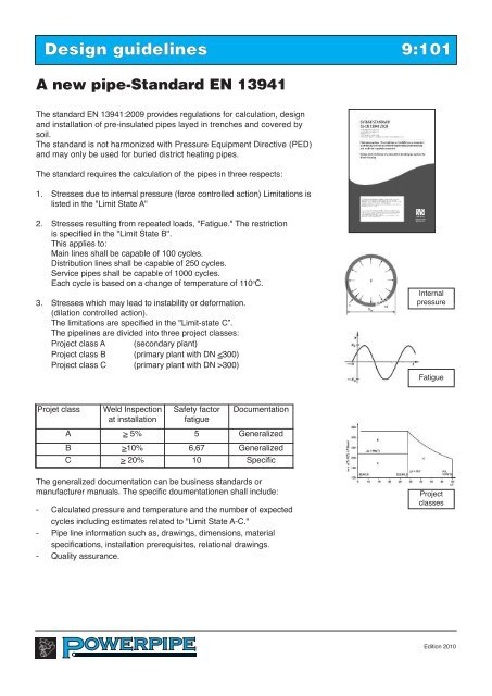
A new pipe-Standard EN 13941<br />
The standard EN 13941:2009 provides regulations for calculation, design<br />
and installation of pre-insulated pipes layed in trenches and covered by<br />
soil.<br />
The standard is not harmonized with Pressure Equipment Directive (PED)<br />
and may only be used for buried district heating pipes.<br />
The standard requires the calculation of the pipes in three respects:<br />
1. Stresses due to internal pressure (force controlled action) Limitations is<br />
listed in the "Limit State A"<br />
2. Stresses resulting from repeated loads, "Fatigue." The restriction<br />
is specified in the "Limit State B".<br />
This applies to:<br />
Main lines shall be capable of 100 cycles.<br />
Distribution lines shall be capable of 250 cycles.<br />
Service pipes shall be capable of 1000 cycles.<br />
Each cycle is based on a change of temperature of 110 o C.<br />
3. Stresses which may lead to instability or deformation.<br />
(dilation controlled action).<br />
The limitations are specified in the "Limit-state C”.<br />
The pipelines are divided into three project classes:<br />
Project class A (secondary plant)<br />
Project class B (primary plant with DN 300)<br />
Internal<br />
pressure<br />
Fatigue<br />
Projet class<br />
Weld Inspection<br />
at installation<br />
Safety factor<br />
fatigue<br />
Documentation<br />
A > 5% 5 Generalized<br />
B >10% 6,67 Generalized<br />
C > 20% 10 Specific<br />
The generalized documentation can be business standards or<br />
manufacturer manuals. The specific doumentationen shall include:<br />
- Calculated pressure and temperature and the number of expected<br />
cycles including estimates related to "Limit State A-C."<br />
- Pipe line information such as, drawings, dimensions, material<br />
specifications, installation prerequisites, relational drawings.<br />
- Quality assurance.<br />
Project<br />
classes<br />
Edition 2010
<strong>Design</strong> <strong>guidelines</strong> 9:102<br />
Forces, movements and expansion types<br />
Expansion<br />
When a buried pipeline is exposed to temperature increase,<br />
this will lead to an expansion of the pipe.<br />
The expansion is counter acted by friction that occurs between<br />
the moving pipe and the surrounding sand (soil).<br />
The friction builds up an axial stress in the pipe and counteract<br />
free expansion.<br />
You get two different zones of the district heating pipe:<br />
1. The part that is fixed (may be in the middleton of a straight<br />
length) (zone 1).<br />
2 The part of the pipe that moves (in both ends of a straight<br />
length) (Zone 2).<br />
The stress in the fixed part depends only on the temperature<br />
change from the temperature when the trench was filled.<br />
The force in the pipe can be calculated as the stress multiplied<br />
by the steel pipes cross area.<br />
The part of the pipe that moves is called "Friction Length".<br />
It acts as a fixative for the fixed part.<br />
Preheating<br />
To limit tensions and movements, it is common that the pipes<br />
are heat-preloaded.<br />
This means that you get compressive stresses in the pipe at high<br />
temperatures and tensile stresses at low temperatures.<br />
Cold Laying<br />
Small and medium-sized dimensions can be layed cold. This<br />
means that you may get exremly high (but in term of norms<br />
acceptable) axial stresses. The movements e.g. of a bend can<br />
be up to four times as large as by pre-heating.<br />
Table of friction lengths and movements<br />
Table of friction length and movements are shown on the next<br />
page. Shown values are based on a number of conditions, as<br />
indicated. When change in the conditions, of course, specified<br />
data will change.<br />
= E . . ∆T<br />
The pipe will expand when<br />
temperatur rises.<br />
Zon 2 Zon 1<br />
Zon 2<br />
Zon 2 Zon 1<br />
Zon 2<br />
Movement counter acted by friction.<br />
Zon 2 Zon 1<br />
Zon 2<br />
Zon 2 Zon 1<br />
Zon 2<br />
= Stress<br />
E = Modulus of elasticity<br />
= Koefficient of thermal<br />
Zon 2 Zon 1<br />
Zon 2<br />
expansion<br />
∆T = Temperature Change<br />
Zon 2 Zon 1<br />
Zon 2<br />
Zon 2 Zon 1<br />
Zon 2<br />
Zon 2 Zon 1<br />
Zon 2<br />
Zon 2 Zon 1<br />
Zon 2<br />
Tension in a preladed pipe<br />
Zon 2 Zon 1<br />
Zon 2<br />
Zon 2 Zon 1<br />
Zon 2<br />
Zon 2 Zon 1<br />
Zon 2<br />
Stresses in a cold layed pipe<br />
Edition 2010
<strong>Design</strong> <strong>guidelines</strong> 9:103<br />
Assumptions for calculations<br />
Maximum axiell stress is 150 Mpa for single pipes (equivalent T=60 o C). Maximum axiell stress is 150+50 Mpa for<br />
double pipes (temperature difference between supply and returning line is 40 o C, soil covering 0,6 m; Bending Radius 3s.<br />
Number of full cycles: 1000 cycles for DN 25-65; 250 cycles for DN80-300; 100 cycles for DN 350-900.<br />
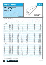
Series 1<br />
Dimension Friction force Friction length Movement Length L-bend<br />
N/m m mm mm<br />
25 956 36 13 0,7<br />
32 1189 42 15 0,8<br />
40 1192 48 18 1,0<br />
50 1376 58 22 1,2<br />
65 1565 65 24 1,6<br />
80 1822 72 27 1,6<br />
100 2359 81 30 1,9<br />
125 2719 87 32 2,4<br />
150 3102 102 38 2,9<br />
200 4130 113 42 3,6<br />
250 5584 116 43 4,2<br />
300 6556 131 48 4,5<br />
350 7524 125 46 5,0<br />
400 8808 138 51 5,6<br />
450 8958 153 56 6,5<br />
500 10516 145 54 6,9<br />
600 12252 163 60 8,2<br />
700 15152 179 66 9,4<br />
800 181216 188 70 10,4<br />
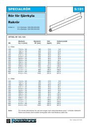
Series 2<br />
Dimension Friction force Friction length Movement Length L-bend<br />
N/m m mm mm<br />
25 1185 29 11 0,5<br />
32 1365 36 13 0,7<br />
40 1368 42 15 0,9<br />
50 1556 52 19 1,2<br />
65 1811 56 21 1,5<br />
80 2075 64 24 1,5<br />
100 2693 71 26 1,8<br />
125 3064 77 28 2,2<br />
150 3530 90 33 2,7<br />
200 4749 98 36 3,4<br />
250 6439 100 37 4,0<br />
300 7449 115 43 4,2<br />
350 8652 109 40 4,6<br />
400 10201 119 44 5,2<br />
450 10351 132 49 6,1<br />
500 12211 125 46 6,4<br />
600 14664 141 52 7,6<br />
700 17568 154 57 8,7<br />
800 20711 165 61 9,8<br />
Series 3<br />
Dimension Friction force Friction length Movement Length L-bend<br />
N/m m mm mm<br />
25 1361 26 9 0,6<br />
32 1545 32 12 0,7<br />
40 1548 37 14 0,9<br />
50 1801 44 16 1,1<br />
65 2063 50 18 1,4<br />
80 2334 57 21 1,6<br />
100 3038 63 23 1,7<br />
125 3492 68 25 2,1<br />
150 4049 78 29 2,5<br />
200 5478 85 31 3,2<br />
250 7326 88 33 3,7<br />
300 8577 100 37 4,4<br />
350 10045 94 35 4,8<br />
400 11897 102 38 5,4<br />
450 12046 113 42 5,6<br />
500 14249 107 40 6,0<br />
600 17080 121 45 7,1<br />
700 20152 134 50 8,2<br />
800 23466 145 54 9,2<br />
Series 4<br />
Dimension Friction force Friction length Movement Length L-bend<br />
N/m m mm mm<br />
25 1539 23 9 0,6<br />
32 1784 28 10 0,7<br />
40 1790 32 12 0,8<br />
50 2062 39 14 1,0<br />
65 2320 44 17 1,3<br />
80 2654 50 19 1,4<br />
100 3461 55 21 1,7<br />
125 4005 59 22 2,0<br />
150 4648 68 25 2,4<br />
200 6204 75 28 3,0<br />
250 8487 76 28 3,5<br />
300 9950 86 32 3,9<br />
350 11621 81 30 4,0<br />
400 13843 88 33 4,5<br />
450 13920 98 37 5,3<br />
500 16612 92 34 5,8<br />
600 19645 105 39 6,6<br />
700 23012 117 44 7,7<br />
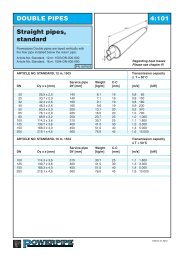
Double, standard<br />
Dimension Friction force Friction length Movement Length L-bend<br />
N/m m mm mm<br />
2*20 1550 23 9 0,4<br />
2*25 1552 33 12 0,6<br />
2*32 1805 36 14 0,9<br />
2*40 1811 41 15 0,8<br />
2*50 2338 45 17 1,1<br />
2*65 2691 50 19 1,4<br />
2*80 3058 56 21 1,4<br />
2*100 4052 62 23 1,7<br />
2*125 5445 57 21 1,9<br />
2*150 6370 65 24 2,3<br />
2*200 8544 71 27 2,9<br />
Double+<br />
Dimension Friction force Friction length Movement Length L-bend<br />
N/m m mm mm<br />
2*20 1805 20 8 0,4<br />
2*25 1805 28 11 0,6<br />
2*32 2319 28 11 0,7<br />
2*40 2328 32 12 0,8<br />
2*50 2675 39 15 1,0<br />
2*65 3040 44 17 1,3<br />
2*80 3402 51 19 1,3<br />
2*100 4523 55 21 1,6<br />
2*125 6234 49 18 1,8<br />
2*150 7116 58 22 2,2<br />
Edition 2010
<strong>Design</strong> <strong>guidelines</strong> 9:104<br />
Backfilling with alternative materials<br />
Shown below are the <strong>guidelines</strong> and potential limitations for the use of alternative backfill materials. If coarse grain<br />
materials are used as backfill around culvert pipes, special attention must be paid to controll during the operation.<br />
Extreme caution must be exercised when handling the backfill mass to avoid damage to pipes and fittings.<br />
Comments<br />
Not congested traffic area Traffic Congested paved Traffic Congested not paved<br />
surface<br />
surface<br />
No exterior load<br />
on the pipes<br />
The pipline assumes to be below<br />
the paved surface, ie. in<br />
earlier existing hard packed<br />
soil.The upper level distributes<br />
the traffic loads so that point<br />
loads not occurs on the pipes.<br />
Risk of point load on the pipes<br />
due to insufficient overfilling<br />
belived missing.<br />
Surrounding material must be<br />
possible to be compacted.<br />
Surrounding material must be<br />
possible to be compacted.<br />
Friction Fixed<br />
distance<br />
Existing natural and/or<br />
mixed material with largest<br />
grain size 50 mm<br />
Joints are enclosed with<br />
protection net of HDPE.<br />
Existing natural and/or<br />
mixed material with largest<br />
grain size 50 mm<br />
Joints are enclosed with<br />
protection net of HDPE.<br />
Existing not sharp-edged naturenatural<br />
material and/or mixed<br />
material with largest grain size<br />
50 mm<br />
Joints are enclosed with<br />
protection net of HDPE.<br />
Expansion distance<br />
(axiell movement)<br />
Existing not sharp-edged natural<br />
material and/or mixed material<br />
with largest grain size 50<br />
mm or mixed material 4-32 mm<br />
grain size.<br />
Joints are enclosed with<br />
mech mat of polyethylene.<br />
Existing not sharp-edged natural<br />
material and/or mixed material<br />
with largest grain size 50 mm or<br />
mixed material 4-32 mm grain<br />
size.<br />
Joints are enclosed with<br />
mech mat of polyethylene.<br />
Not sharp-edged trench gravel<br />
according to AMA tableCEC/1<br />
with the largest grain size 32 mm.<br />
Joints are enclosed with<br />
mech mat of polyethylene.<br />
Expansiondevice<br />
(radiell<br />
movement). For<br />
limited movement<br />
at preheated<br />
systems.<br />
Not sharp-edged trench gravel<br />
according to AMA tableCEC/1<br />
with the largest grain size<br />
32 mm.<br />
Not sharp-edged trench gravel<br />
according to AMA tableCEC/1<br />
with the largest grain size 32 mm<br />
+ foam pads that absorbe the<br />
expansion that exceeds 20 mm.<br />
Not sharp-edged trench gravel<br />
according to AMA tableCEC/1<br />
with the largest grain size<br />
32 mm.<br />
Expansionsdevice<br />
(radiell<br />
movement). For<br />
limited movement<br />
at cold layed<br />
systems.<br />
Not sharp-edged trench gravel<br />
according to AMA table CEC/1<br />
with the largest grain size 32<br />
mm + foam pads with thickness<br />
= least equal to the estimated<br />
movement or natural and/or mixed<br />
material with<br />
largest grain size 50 mm.<br />
Foam pads with thickness<br />
approx 1,6 times the estimated<br />
movement.<br />
Edition 2010
<strong>Design</strong> <strong>guidelines</strong> 9:201<br />
Calculating the pressure-drop for flexible<br />
pipes<br />
Required flow<br />
Each connected house has a power requirement according the design-temperature.<br />
This power requirement with available temperature-drop determines the required flow.<br />
Ex. Power Requiremen Q 12kW.<br />
Temperature drop ∆T 40°C<br />
Required flow m 258 kg/h m = Q*860/∆T<br />
Required dimension<br />
For copper pipes see calculation chart 9:102<br />
With a pressure-drop of 1 mbar/m (10 mm vp/m) the required dimension for the above-stated example<br />
is, 18*1 mm.<br />
Total pressure-drop<br />
The available pressure drop is divided on the longest pipe line from the connection point to the district heating<br />
central located farthest.<br />
Ex: Average pressure-drop can be calculated in terms of type of 1mbar/m.<br />
The pressure-drop on the connecting pipe (Copper-Flex 18*1) if it is 14 m it will be 2*14 * 1 = 28 mbar<br />
Higher pressure-drops can be calculated on the connecting lines located closer to the connection points.<br />
However, water flow should not exceed 2 m/s in a copper pipe.<br />
Edition 2010
<strong>Design</strong> <strong>guidelines</strong> 9:202<br />
Steel flexible pipes<br />
Average Temperature, water 80°C<br />
Roughness ε = 0.0016 mm steelflex<br />
(1 mm vp = 9.81 Pa)<br />
flow in kg/h<br />
effect kW<br />
temperature difference °C<br />
Speed v [m/s]<br />
Example: Power needs 30kW<br />
∆T = 40°C<br />
Required flow = 30 x 860 = 645 kg/h<br />
40<br />
Flow<br />
Pressure drop<br />
Edition 2010
<strong>Design</strong> <strong>guidelines</strong> 9:203<br />
Copper flexible pipes<br />
Average Temperature, water 80°C<br />
Roughness ε = 0.0015 mm copper<br />
(1 mm vp = 9.81 Pa)<br />
flow in kg/h<br />
effect kW<br />
temperature difference °C<br />
Speed v [m/s]<br />
Example: Power needs 30kW<br />
∆T = 40°C<br />
Required flow = 30 x 860 = 645 kg/h<br />
40<br />
Flow<br />
Pressure drop<br />
Edition 2010
<strong>Design</strong> <strong>guidelines</strong> 9:301<br />
Heat losses<br />
Calculation prerequisites for single and double pipe systems<br />
Conditions of installation<br />
Height of back-filling 0,80 m<br />
Distance between pipes 0,20 m Ø 110≤Dy≤ Ø 180<br />
0,25 m Ø 200≤Dy≤ Ø 500<br />
0,30 m Ø 630≤Dy≤ Ø 900<br />
Ground<br />
Thermal conductivity: λ m = 1,5 W/m° K<br />
Heat loss Q<br />
H<br />
T f<br />
T o<br />
λm= soil thermal conductivity<br />
Q<br />
T r<br />
PUR foam insulation:<br />
Thermal conductivity λ i = 0,026 W/m° K<br />
d o<br />
D c<br />
Temperatures, yearly average (primary system):<br />
Flow pipelines Tf = 85 o C<br />
Return pipelines Tr = 55 o C<br />
Ambient temperature To = 5° C<br />
∆T = 65° C<br />
∆T =<br />
T f +Tr<br />
2<br />
– To<br />
If ∆T is changed 10 o , the heat losses are influenced by 10 = 15%<br />
65<br />
C<br />
λ = insulation thermal conductivity<br />
Heat Losses in district heating pipes in the ground depends on:<br />
1 4Z c<br />
1-Thermal resistance of soil: Rm = ln ( )<br />
2πλ m D c<br />
1 D<br />
2- Thermal resistance of pipe insulation Rr = ln ( pur<br />
)<br />
2πλ i d o<br />
1<br />
2Z<br />
3- The interactions between the supply and return line R = ln (1+( c<br />
) 2 )<br />
2 4πλ s<br />
C<br />
For calculation see EN 13941<br />
Edition 2010
<strong>Design</strong> <strong>guidelines</strong> 9:302<br />
Single pipe systems<br />
Heat losses at Δ T = 65° C (includes supply and return lines)<br />
DN Series 1 Series 2 Series 3 Series 4<br />
W/m kWh/m.year W/m kWh/m.year W/m kWh/m.year W(m kWh/m.year<br />
20 14,6 128 13,4 117 12,5 109<br />
25 20,8 182 17,3 151 15,6 137 14,4 126<br />
32 21,3 186 18,8 164 17,0 149 15,3 134<br />
40 24,5 214 21,2 186 19,0 167 17,0 148<br />
50 27,3 239 23,7 208 20,6 180 18,5 162<br />
65 32,1 281 26,6 233 23,1 203 20,7 182<br />
80 33,0 289 27,8 244 24,4 214 21,5 188<br />
100 34,5 302 29,0 254 25,3 221 22,3 195<br />
125 39,9 350 33,4 292 28,2 247 24,4 214<br />
150 47,1 413 37,8 331 31,1 272 26,5 232<br />
200 51,1 448 39,8 349 32,4 284 27,5 241<br />
250 49,2 431 38,8 340 32,4 284 27,8 243<br />
300 56,4 494 44,2 387 35,7 312 29,9 262<br />
350 54,8 480 42,6 373 34,3 301 28,8 253<br />
400 58,1 509 44,1 387 35,2 308 29,5 258<br />
450 85,5 749 58,4 511 43,7 383 35,2 309<br />
500 82,2 720 56,5 495 42,7 374 34,6 303<br />
600 109,8 962 68,4 599 49,3 432 39,8 349<br />
700 134,6 1179 77,7 681 55,8 488 44,8 392<br />
800 152,0 1332 87,3 765 62,4 546<br />
Double pipe systems<br />
Heat losses at Δ T = 65° C<br />
STaNDaRD DoUblE+ DoUblE++<br />
DN W/m kWh/m.year W/m kWh/m.year W/m kWh/m.year<br />
2 x 20 10,1 88 8,9 78 8,1 71<br />
2 x 25 13,2 116 11,2 97 9,9 87<br />
2 x 32 14,6 128 12,2 107 10,8 95<br />
2 x 40 16,6 145 14,3 125 12,4 109<br />
2 x 50 16,4 144 13,8 121 12,2 107<br />
2 x 65 20,2 177 16,3 143 13,7 120<br />
2 x 80 22,8 200 17,8 156 14,6 128<br />
2 x 100 22,9 201 17,4 152 14,4 126<br />
2 x 125 20,8 182 16,7 146 13,6 119<br />
2 x 150 25,6 224 19,7 173 16,1 141<br />
2 x 200 30,5 267 21,8 191 17,3 152<br />
When calculating the heat consumption, the computer program "Ekodim", has EN13941 and the ISO-value<br />
λ = 0.026 W / moC been used, and consideration has been taken that jacket pipes expanded 1%.<br />
When calculating future heat loss confirm the computerized program «Ekodim».<br />
Edition 2010
<strong>Design</strong> <strong>guidelines</strong> 9:303<br />
Heat losses, flexible pipes<br />
Conditions of installation<br />
Filling Height<br />
Free distance between the pipes<br />
Ground<br />
Thermal conductivity:<br />
Insulation PUR foam<br />
Thermal conductivity:<br />
0,6 m<br />
0,1 m<br />
λ m =1,5 W/m°K<br />
λ i =0,024 W/m°K<br />
Temperatures, annual average<br />
Primary- Secondarysystem<br />
system<br />
Supply pipe temp. 85°C 70°C<br />
Return pipe temp. 55°C 40°C<br />
Ambient temp. 5°C 5°C<br />
∆T 65°C 50°C<br />
Heat losses, copper flexible pipes, single<br />
Dimension Primary System W/m kWh/m, year Secondary System W/m kWh/m, year<br />
22/91 13,4 118 10,3 90<br />
28/91 16,1 141 12,4 108<br />
35/91 19,7 172 15,1 133<br />
Heat losses, copper flexible pipes, double<br />
2*15/91 7,4 64 5,7 50<br />
2*18/91 9,3 81 7,2 63<br />
2*22/91 11,5 <strong>101</strong> 8,9 78<br />
2*28/91 14,9 130 11,5 <strong>101</strong><br />
2*18/110 7,5 66 5,8 51<br />
2*22/110 8,7 76 6,7 59<br />
2*28/110 10,2 89 7,8 68<br />
Heat losses, Steel flexible pipes, single<br />
20/78 14,0 122 10,8 94<br />
28/91 16,1 141 12,4 108<br />
The heat losses above are both supply and return direction. If ΔT is changed, the heat losses are affected linearly.<br />
obS! Heat losses increases with time for all District Heating pipes. Ask <strong>Powerpipe</strong> for optimization.<br />
Edition 2010