Series 1, 2, 3 and 4 - Powerpipe
Series 1, 2, 3 and 4 - Powerpipe
Series 1, 2, 3 and 4 - Powerpipe

You also want an ePaper? Increase the reach of your titles
YUMPU automatically turns print PDFs into web optimized ePapers that Google loves.
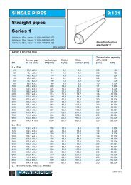
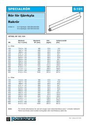
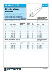
SINGLE PIPES 3:101<br />
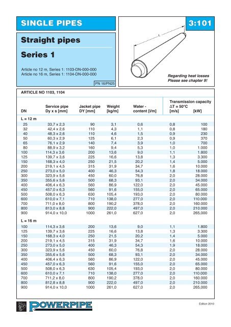
Straight pipes<br />
<strong>Series</strong> 1<br />
Article no 12 m, <strong>Series</strong> 1: 1103-DN-000-000<br />
Article no 16 m, <strong>Series</strong> 1: 1104-DN-000-000<br />
PN 16/PN25<br />
Regarding heat losses<br />
Please see chapter 9!<br />
article no 1103, 1104<br />
transmission capacity<br />
Service pipe Jacket pipe Weight Water - ∆t = 50°c<br />
Dn Dy x s [mm] DY [mm] [kg/m] content [l/m] [m/s] [kW]<br />
l = 12 m<br />
25 33,7 x 2,3 90 3,1 0,6 0,8 100<br />
32 42,4 x 2,6 110 4,3 1,1 0,8 180<br />
40 48,3 x 2,6 110 4,6 1,5 0,9 230<br />
50 60,3 x 2,9 125 6,1 2,3 0,9 370<br />
65 76,1 x 2,9 140 7,4 3,9 1,0 700<br />
80 88,9 x 3,2 160 9,4 5,3 1,0 1.000<br />
100 114,3 x 3,6 200 13,6 9,0 1,1 1.800<br />
125 139,7 x 3,6 225 16,6 13,8 1,3 3.300<br />
150 168,3 x 4,0 250 21,5 20,2 1,4 5.000<br />
200 219,1 x 4,5 315 31,9 34,7 1,6 10.000<br />
250 273,0 x 5,0 400 46,3 54,3 1,8 18.000<br />
300 323,9 x 5,6 450 60,0 76,8 2,0 28.000<br />
350 355,6 x 5,6 500 68,3 93,1 2,0 34.000<br />
400 406,4 x 6,3 560 86,9 122,0 2,0 45.000<br />
450 457,0 x 6,3 560 91,6 155,0 2,0 65.000<br />
500 508,0 x 6,3 630 105,4 193,0 2,0 80.000<br />
600 610,0 x 7,1 710 138,0 277,0 2,0 110.000<br />
700 711,0 x 8,0 800 190,2 378,0 2,0 160.000<br />
800 813,0 x 8,8 900 222,0 497,0 2,0 210.000<br />
900 914,0 x 10,0 1000 261,0 627,0 2,0 265,000<br />
l = 16 m<br />
100 114,3 x 3,6 200 13,6 9,0 1,1 1.800<br />
125 139,7 x 3,6 225 16,6 13,8 1,3 3.300<br />
150 168,3 x 4,0 250 21,5 20,2 1,4 5.000<br />
200 219,1 x 4,5 315 31,9 34,7 1,6 10.000<br />
250 273,0 x 5,0 400 46,3 54,3 1,9 18.000<br />
300 323,9 x 5,6 450 60,0 76,8 2,0 28.000<br />
350 355,6 x 5,6 500 68,3 93,1 2,0 34.000<br />
400 406,4 x 6,3 560 86,9 122,0 2,0 45.000<br />
450 457,0 x 6,3 560 91,6 155,0 2,0 65.000<br />
500 508,0 x 6,3 630 105,4 193,0 2,0 80.000<br />
600 610,0 x 7,1 710 138,0 277,0 2,0 110.000<br />
700 711,2 x 8,0 800 190,2 378,0 2,0 160.000<br />
800 812,8 x 8,8 900 222,0 497,0 2,0 210.000<br />
900 914,0 x 10,0 1000 261,0 627,0 2,0 265,000<br />
Edition 2010
SINGLE PIPES 3:102<br />
Straight pipes<br />
<strong>Series</strong> 2<br />
Article no 12 m, <strong>Series</strong> 2: 1203-DN-000-000<br />
Article no 16 m, <strong>Series</strong> 2: 1204-DN-000-000<br />
PN 16/PN25<br />
Regarding heat losses<br />
Please see chapter 9!<br />
article no 1203, 1204<br />
transmission capacity<br />
Service pipe Jacket pipe Weight Water - ∆t = 50°c<br />
Dn Dy x s [mm] DY [mm] [kg/m] content [l/m] [m/s] [kW]<br />
l = 12 m<br />
20 26,9x2,0 110 3,3 0,4 0,8 65<br />
25 33,7x2,3 110 3,5 0,6 0,8 100<br />
32 42,4x2,6 125 4,6 1,1 0,8 180<br />
40 48,3x2,6 125 5,0 1,5 0,9 230<br />
50 60,3x2,9 140 6,5 2,3 0,9 370<br />
65 76,1x2,9 160 8,0 3,5 1,0 700<br />
80 88,9x3,2 180 10,1 5,3 1,0 1.000<br />
100 114,3x3,6 225 14,8 9,0 1,1 1.800<br />
125 139,7x3,6 250 17,7 13,8 1,3 3.300<br />
150 168,3x4,0 280 23,6 20,2 1,4 5.000<br />
200 219,1x4,5 355 35,1 34,7 1,6 10.000<br />
250 273,0x5,0 450 51,1 54,3 1,8 18.000<br />
300 323,9x5,6 500 65,5 76,8 2,0 28.000<br />
350 355,6x5,6 560 75,7 93,1 2,0 34.000<br />
400 406,4x6,3 630 96,3 121,7 2,0 45.000<br />
450 457,0x6,3 630 101,0 155,0 2,0 65 000<br />
500 508,0x6,3 710 118,0 193,0 2,0 80.000<br />
600 610,0x7,1 800 153,6 277,0 2,0 110.000<br />
700 711,0x8,0 900 210,0 378,0 2,0 160.000<br />
800 813,0x8,8 1000 246,0 497,0 2,0 210.000<br />
900 914,0x10.0 1100 276,0 627,0 2,0 265,000<br />
l = 16 m<br />
100 114,3x3,6 225 14,8 9,0 1,1 1.800<br />
125 139,7x3,6 250 17,7 13,8 1,3 3.300<br />
150 168,3x4,0 280 21,5 20,2 1,4 5.000<br />
200 219,1x4,5 355 35,1 34,7 1,6 10.000<br />
250 273,0x5,0 450 51,1 54,3 1,8 18.000<br />
300 323,9x5,6 500 65,5 76,8 2,0 28.000<br />
350 355,6x5,6 560 75,7 93,1 2,0 34.000<br />
400 406,4x6,3 630 96,3 122,0 2,0 45.000<br />
450 457,0x6,3 630 101,0 155,0 2,0 65.000<br />
500 508,0x6,3 710 118,0 193,0 2,0 80.000<br />
600 610,0x7,1 800 153,6 277,0 2,0 110.000<br />
700 711,0x8,0 900 210,0 378,0 2,0 160.000<br />
800 813,0x8,8 1000 246,0 497,0 2,0 210.000<br />
900 914,0x10,0 1100 276,0 627,0 2,0 265,000<br />
Edition 2010
SINGLE PIPES 3:103<br />
Straight pipes<br />
<strong>Series</strong> 3<br />
Article no 12 m, <strong>Series</strong> 3: 1303-DN-000-000<br />
Article no 16 m, <strong>Series</strong> 3: 1304-DN-000-000<br />
PN 16/PN25<br />
Regarding heat losses<br />
Please see chapter 9!<br />
artcle no 1303, 1304<br />
transmission capacity<br />
Service pipe Jacket pipe Weight Water - ∆t = 50°c<br />
Dn Dy x s [mm] DY [mm] [kg/m] content [l/m] [m/s] [kW]<br />
l = 12 m<br />
20 26,9x2,0 125 3,7 0,4 0,8 65<br />
25 33,7x2,3 125 3,9 0,6 0,8 100<br />
32 42,4x2,6 140 5,0 1,1 0,8 180<br />
40 48,3x2,6 140 5,4 1,5 0,9 230<br />
50 60,3x2,9 160 7,1 2,3 0,9 370<br />
65 76,1x2,9 180 8,7 3,5 1,0 700<br />
80 88,9x3,2 200 10,9 5,3 1,0 1.000<br />
100 114,3x3,6 250 16,2 9,0 1,1 1.800<br />
125 139,7x3,6 280 19,9 13,8 1,3 3.300<br />
150 168,3x4,0 315 25,7 20,2 1,4 5.000<br />
200 219,1x4,5 400 39,0 34,7 1,6 10.000<br />
250 273,0x5,0 500 46,3 54,3 1,8 18.000<br />
300 323,9x5,6 560 76,9 76,8 2,0 28.000<br />
350 355,6x5,6 630 85,1 93,1 2,0 34.000<br />
400 406,4x6,3 710 108,8 122,0 2,0 45.000<br />
450 457,0x6,3 710 113,5 155,0 2,0 65.000<br />
500 508,0x6,3 800 133,6 193,0 2,0 80.000<br />
600 610,0x7,1 900 173,0 277,0 2,0 110.000<br />
700 711,0x8,0 1000 231,8 378,0 2,0 160.000<br />
800 812,8x8,8 1100 267,0 497,0 2,0 210,000<br />
l = 16 m<br />
100 114,3x3,6 250 16,2 9,0 1,1 1.800<br />
125 139,7x3,6 280 19,9 13,8 1,3 3.300<br />
150 168,3x4,0 315 25,7 20,2 1,4 5.000<br />
200 219,1x4,5 400 39,0 34,7 1,6 10.000<br />
250 273,0x5,0 500 46,3 54,3 1,8 18.000<br />
300 323,9x5,6 560 76,9 76,8 2,0 28.000<br />
350 355,6x5,6 630 85,1 93,1 2,0 34.000<br />
400 406,4x6,3 710 108,8 122,0 2,0 45.000<br />
450 457,0x6,3 710 113,5 155,0 2,0 65.000<br />
500 508,0x6,3 800 133,6 193,0 2,0 80.000<br />
600 610,0x7,1 900 173,0 277,0 2,0 110.000<br />
700 711,0x8,0 1000 231,8 378,0 2,0 160.000<br />
800 812,8x8,8 1100 267,0 497,0 2,0 210,000<br />
Edition 2010
SINGLE PIPES 3:104<br />
Straight pipes<br />
<strong>Series</strong> 4<br />
Article no 12 m, <strong>Series</strong> 4: 1403-DN-000-000<br />
Article no 16 m, <strong>Series</strong> 4: 1404-DN-000-000<br />
PN 16/PN25<br />
Regarding heat losses<br />
Please see chapter 9!<br />
article n0 1403, 1404<br />
transmission capacity<br />
Service pipe Jacket pipe Weight Water - ∆t = 50°c<br />
Dn Dy x s [mm] DY [mm] [kg/m] content [l/m] [m/s] [kW]<br />
l = 12 m<br />
20 26,9x2,3 140 4,1 0,4 0,8 65<br />
25 33,7x2,6 140 4,4 0,6 0,8 100<br />
32 42,4x2,6 160 5,5 1,1 0,8 180<br />
40 48,3x2,6 160 6,0 1,5 0,9 230<br />
50 60,3x2,9 180 7,8 2,3 0,9 370<br />
65 76,1x2,9 200 9,6 3,5 1,0 700<br />
80 88,9x3,2 225 11,9 5,3 1,0 1.000<br />
100 114,3x3,6 280 17,4 9,0 1,1 1.800<br />
125 139,7x3,6 315 22,5 13,8 1,3 3.300<br />
150 168,3x4,0 355 28,0 20,2 1,4 5.000<br />
200 219,1x4,5 450 42,0 34,7 1,6 10.000<br />
250 273,0x5,0 560 51,9 54,3 1,8 18.000<br />
300 323,9x5,6 630 82,5 76,8 2,0 28.000<br />
350 355,6x5,6 710 93,5 93,1 2,0 34.000<br />
400 406,4x6,3 800 119,0 122,0 2,0 45.000<br />
450 457,0x6,3 800 124,0 155,0 2,0 65.000<br />
500 508,0x6,3 900 147,0 193,0 2,0 80.000<br />
600 610,0x7,1 1000 189,0 277,0 2,0 110.000<br />
700 711,0x8,0 1100 248,0 378,0 2,0 160.000<br />
l = 16 m<br />
100 114,3x3,6 280 17,4 9,0 1,1 1.800<br />
125 139,7x3,6 315 22,5 13,8 1,3 3.300<br />
150 168,3x4,0 355 28,0 20,2 1,4 5.000<br />
200 219,1x4,5 450 42,0 34,7 1,6 10.000<br />
250 273,0x5,0 560 51,9 54,3 1,8 18.000<br />
300 323,9x5,6 630 82,5 76,8 2,0 28.000<br />
350 355,6x5,6 710 93,5 93,1 2,0 34.000<br />
400 406,4x6,3 800 119,0 122,0 2,0 45.000<br />
450 457,0x6,3 800 124,0 155,0 2,0 65.000<br />
500 508,0x6,3 900 147,0 193,0 2,0 80.000<br />
600 610,0x7,1 1000 189,0 277,0 2,0 110.000<br />
700 711,0x8,0 1100 248,0 378,0 2,0 160.000<br />
Edition 2010
SINGLE PIPES 3:105<br />
Straight pipes for cut<br />
to-length<br />
<strong>Series</strong> 1, 2, 3 <strong>and</strong> 4<br />
Cutting Kapzoner zone<br />
varannan meter<br />
every second<br />
metre<br />
PN 16/PN25<br />
Cut-to-length pipes are manufactured in all dimensions. In these pipes the steel service pipe is covered by<br />
a plastic foil every second metre along the entire pipe length. This arrangement allows easy removal of the<br />
foam from the steel in the sections. These sections of the pipe are indicated on the outside casing pipe.<br />
Whole lengths or parts of pipes cut-to-lenght can be installed at any place in a district heating distribution<br />
system.<br />
cUt-to-lenGtH PiPe 1113, 1213, 1313, 1413<br />
l = 12 m<br />
article no. <strong>Series</strong> 1<br />
1113-DN<br />
article no. <strong>Series</strong> 2<br />
1213-DN<br />
article no. <strong>Series</strong> 3<br />
1313-DN<br />
article no. <strong>Series</strong> 4<br />
1413-DN<br />
For measurement details, see straight pipes!<br />
cUt-to-lenGtH PiPe 1114, 1214, 1314, 1414<br />
l = 16 m<br />
article no. <strong>Series</strong> 1<br />
1114-DN<br />
article no. <strong>Series</strong> 2<br />
1214-DN<br />
article no. <strong>Series</strong> 3<br />
1314-DN<br />
article no. <strong>Series</strong> 4<br />
1414-DN<br />
For measurement details, see straight pipes!<br />
Pipes are available with «center-cut" This will be indicated in separate line of text.<br />
an example of how to order:<br />
Cut-to-length pipe DN 200, series 2, 12 m has Article no. 1213-200-000-000.<br />
Edition 2010
SINGLE PIPES 3:106<br />
Curved pipes<br />
<strong>Series</strong> 1, 2, 3 <strong>and</strong> 4<br />
Deflection<br />
PN 16/PN25<br />
cUrveD PiPeS 1123, 1124, 1223, 1224, 1323, 1324, 1423, 1424<br />
Single pipes<br />
Max. deflection<br />
Dn l = 12 m l = 16 m note<br />
25 - 80 35 o To be bent at installation site<br />
80 - 100 35 o Bent at <strong>Powerpipe</strong> works<br />
125 - 150 30 o 25 o Bent at <strong>Powerpipe</strong> works<br />
200 25 o 33 o Bent at <strong>Powerpipe</strong> works<br />
250 25 o 33 o Bent at <strong>Powerpipe</strong> works<br />
300 20 o 25 o Bent at <strong>Powerpipe</strong> works<br />
350 14 o 23 o Bent at <strong>Powerpipe</strong> works<br />
400 11-(18) o 15-(22) o Bent at <strong>Powerpipe</strong> works *<br />
450 7-(11) o 11-(18) o Bent at <strong>Powerpipe</strong> works *<br />
500 5-(9) o 8-(12) o Bent at <strong>Powerpipe</strong> works *<br />
600 – 8 o Bent at <strong>Powerpipe</strong> works*<br />
* See note below concerning wall thickness.<br />
In paranteses; the specified values relates thickness higher than st<strong>and</strong>ard.<br />
Accuracy of manufacture DN 100 - 200 +/- 2°<br />
DN 250 - 600 +/- 1°<br />
Steel pipes:<br />
For the manufacturing either seamless steel pipes or longitudinally welded steel pipes are used.<br />
DN 450, DN 500 <strong>and</strong> DN 600 steel pipes with extra wall thickness will be used. Increased wall<br />
thickness for smaller dimensions will allow deflection exceeding above normal max. deflection.<br />
This can be delivered on request. However, this means increased prices <strong>and</strong> longer delivery<br />
time. For larger sizes (DN700-900) segment-weldeet curved pipes can be offered.<br />
For manufacturing technical reasons, the alarm wires placed in neutral position, ie c. at. 12 <strong>and</strong> 6.<br />
article no. series 1<br />
1123-DN-000-000 for 12 m pipe length<br />
1124-DN-000-000 for 16 m pipe length<br />
article no. series 2<br />
1223-DN-000-000 for 12 m pipe length<br />
1224-DN-000-000 for 16 m pipe length<br />
article no. series 3<br />
1323-DN-000-000 for 12 m pipe length<br />
1324-DN-000-000 for 16 m pipe length<br />
article no. series 4<br />
1423-DN-000-000 for 12 m pipe length<br />
1424-DN-000-000 for 16 m pipe length<br />
an example of how to order:<br />
Curved pipe series 1, L = 12 m with dim DN 200.<br />
has Article No. 1123-200-000-000, Deflection shall be stated in a separate line of text.<br />
Edition 2010
SINGLE PIPES 3:107<br />
Curved pipes<br />
Deflection versus design<br />
radius<br />
<strong>Series</strong> 1, 2, 3 <strong>and</strong> 4<br />
PN 16/PN25<br />
Design radius<br />
length<br />
Deflection<br />
correlation BetWeen DeFlection anD DeSiGn raDiUS<br />
Design radius<br />
Design radius<br />
Deflection l = 12 m l = 16 m Deflection l = 12 m l = 16 m<br />
1° 690 910 21° 33,0 44,0<br />
2° 345 460 22° 31,0 42,0<br />
3° 230 305 23° 30,0 40,0<br />
4° 170 230 24° 29,0 38,0<br />
5° 140 185 25° 28,0 37,0<br />
6° 115 155 26° 27,0 36,0<br />
7° 98 130 27° 26,0 34,0<br />
8° 86 115 28° 25,0 33,0<br />
9° 76 100 29° 24,0 32,0<br />
10° 69 92 30° 23,2 30,9<br />
11° 62 83 31° 22,5 30,0<br />
12° 57 76 32° 21,8 29,1<br />
13° 53 71 33° 21,1 28,1<br />
14° 49 65 34° 20,5 27,3<br />
15° 46 61 35° 20,0 26,7<br />
16° 43 57 36° 19,4 25,8<br />
17° 40 54 37° 18,9 25,2<br />
18° 38 51 38° 18,4 24,6<br />
19° 36 48 39° 18,0 23,9<br />
20° 34 46 40° 17,5 23,4<br />
Pipe trench:<br />
A pre-insulated pipe DN>250 cannot be bent along its entire length. At each pipe end a<br />
straight part will remain, which shall be approximately 2 meters in lenght.<br />
This deviation from an ideal curved pipe radius is to be compensated when installing the pipe<br />
by making the pipe trench approximately 150 mm wider.<br />
The widening should be ~200 mm at deviation < 10 o<br />
The widening should be ~500 mm at deviation > 10 o<br />
Edition 2010
SINGLE PIPES 3:108<br />
Curved pipes<br />
Elastic radius<br />
deflection<br />
<strong>Series</strong> 1, 2 , 3 <strong>and</strong> 4<br />
Design radius<br />
Length<br />
PN 16/PN25<br />
elaStic raDiUS<br />
Dimension elastic radius Deflection<br />
Dn m 12 m<br />
25 15 45,0°<br />
40 21 31,0°<br />
50 27 25,0°<br />
65 34 20,0°<br />
80 40 17,0°<br />
100 52 13,0°<br />
125 63 11,0°<br />
150 76 9,0°<br />
200 98 7,0°<br />
250 122 5,6°<br />
300 145 4,7°<br />
400 182 3,7°<br />
500 227 3,0°<br />
600 273 2,5°<br />
The above table shows the elastic radius which is the maximum radius or deflection that can<br />
be allowed without permanent deformation of the steel pipe.<br />
Edition 2010
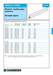
SINGLE PIPES 3:201<br />
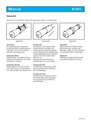
Bend<br />
<strong>Series</strong> 1, 2, 3 <strong>and</strong> 4<br />
<strong>Powerpipe</strong> bends are manufactured using a special<br />
foam with high compressive strength, which means<br />
that dilatation absorbent material would normally<br />
be unnecessary.<br />
article no 2100, 2200, 2300, 2400<br />
PN 16/PN25<br />
Service pipe<br />
Jacket pipe<br />
<strong>Series</strong> 1 <strong>Series</strong> 2 <strong>Series</strong> 3 <strong>Series</strong> 4 l<br />
Dn Dy x s [mm] DY [mm] DY [mm] DY [mm] DY [mm] [mm]<br />
20 26,9x2,3 - 110 125 140 1000<br />
25 33,7x2,6 90 110 125 140 1000<br />
32 42,4x2,6 110 125 140 160 1000<br />
40 48,3x2,6 110 125 140 160 1000<br />
50 60,3x2,9 125 140 160 180 1000<br />
65 76,1x2,9 140 160 180 200 1000<br />
80 88,9x3,2 160 180 200 225 1000<br />
100 114,3x3,6 200 225 250 280 1000<br />
125 139,7x3,6 225 250 280 315 1000<br />
150 168,3x4,0 250 280 315 355 1000<br />
200 219,1x4,5 315 355 400 450 1000<br />
250 273,0x5,0 400 450 500 560 1300<br />
300 323,9x5,6 450 500 560 630 1500<br />
350 355,6x5,6 500 560 630 710 1600<br />
400 406,4x6,3 560 630 710 800 1600<br />
450 457,0x6,3 560 530 710 800 1600<br />
500 508,0x6,3 630 710 800 900 1600<br />
600 610,0x7,1 710 800 900 1000 1600<br />
700 711,0x8,0 800 900 1000 1100 1700<br />
800 813,0x8,8 900 1000 1100 1850<br />
900 914,0x10,0 1000 1100 2000<br />
Bends are, as st<strong>and</strong>ard, available as 90° <strong>and</strong> 45°.<br />
Bends having other degrees, such as 75°, 60°, 30° <strong>and</strong> 15°, <strong>and</strong> bends having leg lengths other than<br />
specified in the above table can be delivered on special request.<br />
article no. <strong>Series</strong> 1<br />
2100-DN-degree of bend-000<br />
article no. <strong>Series</strong> 2<br />
2200-DN-degree of bend-000<br />
Space for sleeve<br />
In order to fit the sleeve at installation of DN50-DN200<br />
extended leg 1200x 1200 mm are offered. State suffix 999<br />
article no. <strong>Series</strong> 3<br />
an example of how to order:<br />
2300-DN-degree of bend-000 Bend, series 1, dim DN100, 90°<br />
has Article No. 2100-100-900-000.<br />
article no. <strong>Series</strong> 4<br />
2400-DN-degree of bend-000<br />
Edition 2010
SINGLE PIPES 3:202<br />
Termination bend 90°<br />
1500<br />
<strong>Series</strong> 1, 2, 3 <strong>and</strong> 4<br />
The termination bend has a special PDPE sealing at<br />
one pipe end. This seal will efficiently prevent water<br />
from penetrating into the foam when installing the<br />
bend. The built in alarm wires are<br />
linked outside the sealing.<br />
PN 16/PN25<br />
1500<br />
article no 2110, 2210, 2310<br />
Service pipe<br />
Jacket pipe<br />
<strong>Series</strong> 1 <strong>Series</strong> 2 <strong>Series</strong> 3 <strong>Series</strong> 4<br />
Dn Dy x s [mm] DY [mm] DY [mm] DY [mm] DY [mm]<br />
20 26,9x2,3 – 110 125 140<br />
25 33,7x2,6 90 110 125 140<br />
32 42,4x2,6 110 125 140 160<br />
40 48,3x2,6 110 125 140 160<br />
50 60,3x2,9 125 140 160 180<br />
65 76,1x2,9 140 160 180 200<br />
80 88,9x3,2 160 180 200 225<br />
100 114,3x3,6 200 225 250 280<br />
125 139,0x3,6 225 250 280 315<br />
150 168,3x4,0 250 280 315 355<br />
200 219,1x4,5 315 355 400 450<br />
250 273,0x5,0 400 450 500 560<br />
300 323,9x5,6 450 500 560 630<br />
Other degrees <strong>and</strong>/or leg lengths can be supplied on request.<br />
article no. series 1<br />
2110-DN-000-000<br />
article no. series 2<br />
2210-DN-000-000<br />
article no. series 3<br />
2310-DN-000-000<br />
article no. series 4<br />
2410-DN-000-000<br />
Termination bend, 90 o , with other leg lengths <strong>and</strong> deflection<br />
can be delivered on request.<br />
an example of how to order:<br />
Termination bend series 1<br />
dim DN 50, has article no. 2110-050-000-000.<br />
Gravel refilling may not reach the<br />
end cap, alarm wire or marker<br />
tape.<br />
The sealing shall not be below<br />
water table continuously.<br />
Edition 2010
SINGLE PIPES 3:301<br />
T-piece<br />
<strong>Series</strong> 1, 2, 3 <strong>and</strong> 4<br />
<strong>Powerpipe</strong> T-pieces are as st<strong>and</strong>ard delivered in<br />
a reinforced design if not otherwise is indicated.<br />
PN 16/PN25<br />
article no 3100, 3200, 3300, 3400<br />
Main pipe Branch pipe l1 l2<br />
Dn Dn [mm] [mm]<br />
25-200 25-80 1200 1000<br />
100-200 100-200 1500 1000<br />
250-900 25-80 1200 1200<br />
250-900 100-200 1500 1200<br />
250-900 250-600 1800 1500<br />
700-900 700-900 2100 1700<br />
The branch pipe cannot be designed in dimensions bigger than the main pipe.<br />
article no. series 1<br />
3100-DN main pipe-DN branch pipe-000<br />
article no. series 2<br />
3200-DN main pipe-DN branch pipe-000<br />
article no. series 3<br />
3300-DN main pipe-DN branch pipe-000<br />
Space for sleeve<br />
In order to fit the sleeve at installation of T-piece with<br />
branch pipe max DN200, product with extended L1-<br />
dimensions with 800 mm are offered <strong>and</strong> L2-dimensions<br />
with 400 mm for DN 25-80, L2-dimensions with<br />
700 mm for DN 100-200<br />
State suffix: 999.<br />
article no. series 4<br />
3400-DN main pipe-DN branch pipe-000<br />
an example of how to order:<br />
T-piece series 1 med main pipe DN 200 <strong>and</strong> branch pipe DN 50,<br />
has article no. 3100-200-050-000.<br />
Alt. (extended T-piece) has article no. 3100-200-050-999<br />
Edition 2010
L3<br />
L2<br />
SINGLE PIPES 3:302<br />
T-piece with<br />
extended branch<br />
<strong>Series</strong> 1, 2, 3 <strong>and</strong> 4<br />
<strong>Powerpipe</strong> T-pieces with extended branch length shall<br />
be used in such cases when the systems design require<br />
the installation of a valve unit or a transition unit in<br />
the branch directly after the T-piece. PN 16/PN25<br />
article no 3120, 3220, 3320, 3420<br />
50<br />
L1<br />
Main pipe For l1 <strong>and</strong> l2 l3 [mm] l3 [mm]<br />
Dn see page 3:301 <strong>Series</strong> 1 <strong>and</strong> 2 <strong>Series</strong> 3 <strong>and</strong> 4<br />
25-50 330<br />
65-80 370<br />
100-125 500<br />
150 530<br />
200 600<br />
250 700<br />
300 750 860<br />
350 850 930<br />
400 930 1000<br />
500 1000 1100<br />
600 1100 1200<br />
700 1200 1300<br />
800 1300 1400<br />
900 1400 1500<br />
The branch pipe cannot be designed in dimensions bigger than the main pipe<br />
article no. series 1<br />
3120-DN main pipe-DN branch pipe-000<br />
article no. series 2<br />
3220-DN main pipe-DN branch pipe-000<br />
article no. series 3<br />
3320-DN main pipe-DN branch pipe-000<br />
article no. series 4<br />
3420-DN main pipe-DN branch pipe-000<br />
an example of how to order:<br />
T-piece series 1 with main pipe DN 200 <strong>and</strong> branch pipe DN 50,<br />
has Article No. 3120-200-050-000.<br />
Edition 2010
SINGLE PIPES 3:303<br />
T-piece, straight<br />
<strong>Series</strong> 1, 2, 3 <strong>and</strong> 4<br />
<strong>Powerpipe</strong> T-pieces are as st<strong>and</strong>ard delivered in a<br />
reinforced design if not otherwise is indicated.<br />
With T-piece straight branching can be performed<br />
at the same level as the main pipe.<br />
PN 16/PN25<br />
L1<br />
L2<br />
article no 3130, 3230, 3330, 3430<br />
Main pipe Branch pipe l1 l2<br />
Dn Dn [mm] [mm]<br />
25-200 25-100 1200 700<br />
125-200 125-200 1500 700<br />
250-500 25-100 1200 900<br />
250-500 125-200 1500 900<br />
250-500 250-400 1800 900<br />
600-900 25-100 1200 1100<br />
600-900 125-200 1500 1100<br />
600-900 250-500 1800 1100<br />
600-900 600-800 2100 1100<br />
The branch pipe cannot be designed in dimensions bigger than the main pipe.<br />
article no. series 1<br />
3130-DN main pipe-DN branch pipe-000<br />
article no. series 2<br />
3230-DN main pipe-DN branch pipe-000<br />
article no. series 3<br />
3330-DN main pipe-DN branch pipe-000<br />
article no. series 4<br />
3430-DN main pipe-DN branch pipe-000<br />
an example of how to order:<br />
T-piece series 1 with main pipe DN 200 <strong>and</strong> branch pipe DN 50,<br />
has Article No. 3130-200-050-000.<br />
Edition 2010
SINGLE PIPES 3:304<br />
T-pieces with parallel<br />
branch<br />
<strong>Series</strong> 1, 2, 3 <strong>and</strong> 4<br />
<strong>Powerpipe</strong> T-pieces are as st<strong>and</strong>ard delivered in<br />
a reinforced design if not otherwise is indicated.<br />
H<br />
150<br />
L1<br />
PN 16/PN25<br />
article no 3110, 3210, 3310, 3410<br />
Main pipe Branch pipe l1<br />
Dn Dn [mm]<br />
25-900 25-100 1200<br />
125-900 125-200 1500<br />
250-900 250-400 1800<br />
450-900 450-500 2400<br />
H<br />
150<br />
L1<br />
H = DY Main pipe + DY Branch pipe + 150 (For branch pipe DN450 <strong>and</strong> DN500 the H-dimension will be<br />
2 100 mm more)<br />
example:<br />
Main pipe DN 100/225<br />
Branch pipe DN 40/125<br />
H = 225 + 125 +150 = 325 mm<br />
2<br />
The branch pipe cannot be designed in dimensions larger than the main pipe.<br />
article no. series 1<br />
3110-DN main pipe-DN branch pipe-000<br />
article no. series 2<br />
3210-DN main pipe-DN branch pipe-000<br />
article no. series 3<br />
3310-DN main pipe-DN branch pipe-000<br />
article no. series 4<br />
3410-DN main pipe-DN branch pipe-000<br />
an example of how to order:<br />
T-piece series 1 with main pipe DN 200 <strong>and</strong> branch pipe DN 50,<br />
has Article No. 3110-200-050-000.<br />
Edition 2010
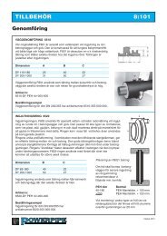
SINGLE PIPES B 3:305<br />
Air release/ drainage<br />
units<br />
<strong>Series</strong> 1, 2, 3 <strong>and</strong> 4<br />
The built-in alarmwires are linked outside the sealing.<br />
H<br />
1500 1200<br />
PN 16/PN25<br />
article no 3140, 3240, 3340, 3440<br />
Main pipe H air release/ drainage B-measure<br />
Dn [mm] Dn [mm]<br />
25 409 25 110<br />
32 414 40 110<br />
150<br />
40 417 50 H 125<br />
50 423 65 140<br />
65 431<br />
80 438<br />
100 450<br />
125 463<br />
150 477<br />
200 502<br />
250 530<br />
300 554<br />
350 570<br />
400 596<br />
500 650<br />
600 700<br />
700 758<br />
800 800<br />
900 850<br />
L1<br />
Please observe: the included<br />
ball valve has to be operated<br />
at least twice/year in order to<br />
ensure a good function.<br />
The valve is made of stainless steel. Air release/ drainage units<br />
are equipped with screwed on plug <strong>and</strong> comes in DN 25, DN 40,<br />
DN 50 <strong>and</strong> DN65. As air release unit DN25 is recomended <strong>and</strong> as drain<br />
unit DN50 is recomended.<br />
The valve is protected by a end cap as a st<strong>and</strong>ard. Se sid 8:102<br />
Please observe: Do not refill<br />
above the sealing.<br />
The sealing shall not be below<br />
water table continuously.<br />
article no. series 1 article no. series 3<br />
3140-DN main pipe-DN release/ drainage-000<br />
3340-DN main pipe-DN release/ drainage-000<br />
article no. series 2 article no. series 4<br />
3240-DN main pipe-DN release/ drainage-000<br />
3440-DN main pipe-DN release/ drainage-000<br />
an example of how to order:<br />
Air release for main pipe series 1 with main pipe DN 200 <strong>and</strong><br />
air release DN 25, has Article No. 3140-200-025-000.<br />
Edition 2010
SINGLE PIPES 3:401<br />
Valves<br />
<strong>Series</strong> 1, 2, 3 <strong>and</strong> 4<br />
The unit consists of a maintenance free ball valve in<br />
a fully welded housing together with a corrosion free<br />
ball. All valves according to EN448 are supplied to<br />
st<strong>and</strong> the yield strength as the pipe line. The built in<br />
alarmwires are linked outside the sealing.<br />
PN 16/PN25<br />
L<br />
article no 4100, 4200, 4300, 4400<br />
Main pipe Service pipe l H B Wrench size Delivered<br />
Dn Dy x s mm [mm] [mm] [mm] [mm] with<br />
25 33,7 x 2,3 1500 382 110 19<br />
32 42,4 x 2,6 1500 388 110 19<br />
150<br />
40 48,3 x 2,6 1500 401 110 19<br />
H<br />
L1<br />
50 60,3 x 2,9 1500 411 110 19 Adapter for<br />
65 76,1 x 2,9 1500 415 110 19 T-key<br />
80 88,9 x 3,2 1500 426 110 19<br />
100 114,3 x 3,6 1500 450 125 27<br />
125 139,7 x 3,6 1500 455 125 27<br />
150 168,3 x 4,0 1500 474 125 27<br />
200 219,1 x 4,5 1500 520 160 50 adapter for<br />
250 273,0 x 5,0 1500 557 160 50 portable gear<br />
300 323,9 x 5,6 1800 664 160 50<br />
350 355,6 x 5,6 1800 906 350<br />
400 406,4 x 6,3 2000 977 350 Mounted gear<br />
500 508,3x6,3 custom 1056 350<br />
600 610,0x7,1 custom 1183 350<br />
H-measure does not include gear, hydraulic or electric actuator. For valves DN700 <strong>and</strong> DN800 see separate<br />
specification. Gate valve can be quoted on request. Other design for example with full bore can be supplied on<br />
request. Valves can be supplied with T-key, portable planetary gear <strong>and</strong> protection pipe for valve stem extension,<br />
length 1500 mm, <strong>and</strong> hydraulic or electric actuator, see accessories!<br />
AS st<strong>and</strong>ard the valves are delivered with:<br />
DN25-DN125 with adapter for T-key.<br />
DN150-DN300 with adapter for portable gear.<br />
DN350-DNxx with fixed gear.<br />
article no. series 1 article no. series 2<br />
4100-DN-000-000<br />
4200-DN-000-000<br />
article no. series 3 article no. series 4<br />
4300-DN-000-000<br />
4400-DN-000-000<br />
The valve is protected by a end cap of PEH as a st<strong>and</strong>ard. See 8:102<br />
Available with separate measuring box as extra order, se 7:302.<br />
an example of how to order:<br />
Valves series 1 with main pipe DN 200,<br />
has Article No. 4100-200-000-000.<br />
Please observe: the included ball<br />
valve has to be operated at least<br />
twice/year in order to ensure a<br />
good function.<br />
Please observe: Do not refill above<br />
the sealing.<br />
The sealing shall not be below<br />
water table continuously.<br />
Edition 2010
B D<br />
SINGLE PIPES 3:402<br />
Preinsulated valve<br />
with one air release/<br />
drainage unit<br />
<strong>Series</strong> 1, 2, 3 <strong>and</strong> 4<br />
The built in alarmwires are linked outside the sealing.<br />
PN 16/PN25<br />
c<br />
L<br />
article no 4141, 4241, 4341, 4441<br />
air release/ drainage<br />
Main pipe l c H B Wrench size Delivered D-dim<br />
Dn [mm] [mm] [mm] [mm] [mm] with Dn [mm]<br />
25 1500 250 382 110 19 25 110<br />
32 1500 250 388 110 19 40 110<br />
150<br />
40 1500 250 401 110 19 50<br />
H<br />
L1125<br />
50 1500 250 411 110 19 Adapter 65 140<br />
65 1500 250 415 110 19 for T-key<br />
80 1500 250 426 110 19<br />
100 1500 250 450 125 27<br />
125 1500 250 455 125 27<br />
150 1500 250 474 125 27<br />
200 1500 250 520 160 50 Adapter for<br />
250 1500 350 557 160 50 portable gear<br />
300 1800 350 664 160 50<br />
350 1800 350 906 350<br />
400 2000 450 977 350 Mounted gear<br />
500 2200 550 1056 350<br />
600 2400 640 1183 350<br />
The valve stems are installed in position towards the stop valve. Air release/ drainage units are manufactured in<br />
dimension DN25, DN40, DN50 <strong>and</strong> DN65 are delivered with a screwed on plug. Both air release/ drainage<br />
units are delivered in the same dimension.<br />
The valve is protected by a end cap as a st<strong>and</strong>ard. Se sid 8:102<br />
article no. series 1 article no. series 2<br />
4141-DN main pipe-DN air release-000 4241-DN main pipe-DN air release-000<br />
article no. series 3<br />
4341-DN main pipe-DN air release-000<br />
article no. series 4<br />
4441-DN main pipe-DN air release-000<br />
Available with separate measuring box as extra order, see 7:302<br />
an example of how to order:<br />
Valve series 2 with main pipe DN 100 <strong>and</strong> air release DN 25,<br />
has Article No. 4241-100-025-000.<br />
Please observe: the included<br />
ball valve has to be operated<br />
at least twice/year in order to<br />
ensure a good function.<br />
Please observe: Do not refill<br />
above the sealing.<br />
The sealing shall not be below<br />
water table continously.<br />
Edition 2010
SINGLE PIPES 3:403<br />
Valve with double air<br />
release/drainage<br />
units<br />
<strong>Series</strong> 1, 2, 3 <strong>and</strong> 4<br />
The built in alarmwires are linked outside<br />
the sealing.<br />
PN 16/PN25<br />
D<br />
C<br />
C<br />
L<br />
St<strong>and</strong>ard design<br />
(See alternative design at page 3:404)<br />
H<br />
article no 4142, 4242, 4342, 4442<br />
air release/ drainage<br />
Main pipe l c H Wrench size Dn D-dim<br />
St<strong>and</strong>ard<br />
[mm]<br />
Dn [mm] [mm] [mm] [mm]<br />
25 1500 250 382 19 25 110<br />
150<br />
32 1500 250 388 19 H<br />
40 L110<br />
40 1500 250 401 19 50 125<br />
Adapter<br />
50 1500 250 411 19 65 140<br />
for<br />
65 1500 250 415 19<br />
T-key<br />
80 1500 250 426 19<br />
100 1500 250 450 27<br />
125 1500 250 455 27<br />
150 1500 250 474 27 Adapter<br />
200 1500 250 520 50 for<br />
250 1500 350 557 50 portable<br />
300 1800 350 664 50 gear<br />
350 1800 350 906<br />
400 2000 450 977<br />
Mounted<br />
500 2200 550 1056<br />
gear<br />
600 2400 640 1183<br />
The valve stems are installed in position towards the stop valve. Air release/ drainage units are manufactured in<br />
dimension DN25, DN40, DN50 <strong>and</strong> DN65 are delivered with a screwed on plug. Both air release/ drainage<br />
units are delivered in the same dimension.<br />
The valve is protected by a end cap as a st<strong>and</strong>ard. Se sid 8:102<br />
article no. series 1<br />
4142-DN main pipe-DN air release-000<br />
article no. series 2<br />
4242-DN main pipe-DN air release-000<br />
article no. series 3<br />
4342-DN main pipe-DN air release-000<br />
article no. series 4<br />
4442-DN main pipe-DN air release-000<br />
an example of how to order:<br />
Valve series 2 with main pipe DN 100 <strong>and</strong> air release<br />
DN 25, has Article No. 4242-100-025-000.<br />
Please observe: the included ball valve has to be<br />
operated at least twice/year in order to ensure a<br />
good function.<br />
Please observe: Do not refill above the sealing.<br />
The sealing shall not be below water table<br />
continously.<br />
Edition 2010
Design<br />
Dp<br />
SINGLE PIPES 3:404<br />
622<br />
Valve with 2 pc. air<br />
releasear/drainage<br />
(optional design)<br />
D<br />
H<br />
L<br />
D<br />
C<br />
D<br />
H<br />
<strong>Series</strong> 1, 2, 3 <strong>and</strong> 4<br />
The built in alarmwires are linked outside<br />
the sealing.<br />
PN 16/PN25<br />
Design<br />
637<br />
L<br />
1.500<br />
article no 4142, 4242, 4342, 4442<br />
air release/ drainage<br />
Main pipe l l c H Dp Wrench size Dn D-mått<br />
622 637 [mm] [mm]<br />
Dn [mm] [mm] [mm] [mm] [mm] [mm]<br />
25 1500 2750 250 382 235 19 25 110<br />
32 1500 2750 250 388 235 19 40 110<br />
40 1500 2750 250 401 235 19 50 125<br />
Adapter<br />
50 1500 2750 250 411 235 19 65 140<br />
for<br />
65 1500 2750 250 415 295 19<br />
T-Key<br />
80 1500 2750 250 426 295 19<br />
100 1500 2750 250 450 295 27<br />
125 1500 2750 250 455 340 27<br />
150 1500 2750 250 474 415 27 Adapter<br />
200 1500 2750 250 520 415 50 for<br />
250 1500 2850 350 557 415 50 portablel<br />
300 1800 2850 350 664 415 50 gear<br />
350 1800 2850 350 906<br />
400 2000 2950 450 977<br />
Mounted<br />
500 2200 3050 550 1056<br />
gear<br />
600 2400 3150 640 1183<br />
The valve stems are installed in position towards the stop valve. Air release/ drainage units are manufactured in<br />
dimension DN25, DN40, DN50 <strong>and</strong> DN65 are delivered with a screwed on plug. Both air release/ drainage<br />
units are delivered in the same dimension.<br />
The valve is protected by a end cap as a st<strong>and</strong>ard. Se sid 8:102<br />
Design 622 has suffix 622<br />
Design 637 has suffix 637<br />
an example of how to order:<br />
Valve series 2 with main pipe DN 300 <strong>and</strong> air<br />
release DN 40 in design 622, has Article No.<br />
4242-300-040-622 <strong>and</strong> design 637 has<br />
Article No. 4242-300-040-637<br />
Please observe: the included ball valve has to be<br />
operated at least twice/year in order to ensure a<br />
good function.<br />
Please observe: Do not refill above the sealing.<br />
The sealing shall not be below water table<br />
continously.<br />
Edition 2010
Design<br />
SINGLE PIPES 3:405<br />
Valve with 2 pc.<br />
pro-tected air release/<br />
drainage (optional design)<br />
635<br />
Dp<br />
DA<br />
H<br />
L2<br />
<strong>Series</strong> 1, 2, 3 <strong>and</strong> 4<br />
The built in alarmwires are linked outside<br />
the sealing.<br />
PN 16/PN25<br />
L<br />
article no 4142, 4242, 4342, 4442 Design 635 air release/ drainage<br />
Main pipe l Dp air release H Wrench size Dn Da l2<br />
Dn [mm] [mm]<br />
Dn [mm] [mm] [mm] [mm] [mm]<br />
25 1500 382 19 25 150 300<br />
32 1500 388 19 40 180 350<br />
40 1500 180 25 401 19<br />
50 1500 180 25 411 19<br />
65 1500 180 25 415 19<br />
80 1500 180 25 426 19<br />
100 1500 180 25 450 27<br />
125 1500 180 25 455 27<br />
150 1500 180 25 474 27<br />
200 1500 225 40 520 50<br />
250 1500 225 40 557 50<br />
300 1800 225 40 664 50<br />
Adapter<br />
for<br />
T-Key<br />
Adapter<br />
for<br />
portable<br />
gear<br />
Air release/ drainage units are manufactured in dimension DN25, DN40, DN50 <strong>and</strong> DN65 are delivered with a<br />
screwed on plug.<br />
Desired connections can be executed in the threaded end. Valve stems are facing upwards.<br />
Both air release / drainage units are delivered in the same dimension.<br />
The valve is protected by a hut made of stainless steel as a st<strong>and</strong>ard. Please see 8:102<br />
an example of how to order:<br />
Valve series 2 with main pipe DN 300 <strong>and</strong><br />
air release DN 40 in design 635, has Article No.<br />
4242-300-040-635<br />
Please observe: the included ball valve has to be<br />
operated at least twice/year in order to ensure a<br />
good function.<br />
Please observe: Do not refill above the sealing.<br />
The sealing shall not be below water table<br />
continously.<br />
Edition 2010
SINGLE PIPES 3:406<br />
Combination valve<br />
St<strong>and</strong>ard design<br />
<strong>Series</strong> 1, 2, 3 <strong>and</strong> 4<br />
● Air release<br />
● Drain<br />
● Bypass<br />
article no 4841, 4842, 4843, 4844<br />
PN 16/PN25<br />
Main pipe D By pas valves l a D a B H<br />
<strong>Series</strong> 2 valves<br />
Dn [mm] Dn (3 st) [mm] [mm] [mm] [mm] [mm]<br />
100 225 25 1800 650 110 415 500<br />
125 250 25 1800 650 125 415 500<br />
150 280 32 1800 700 125 415 530<br />
200 355 40 1800 700 125 415 560<br />
250 450 40 1800 700 125 450 600<br />
300 500 50 2100 750 140 450 700<br />
D<br />
H<br />
B<br />
L<br />
D A<br />
St<strong>and</strong>ard design<br />
A<br />
Ball valve comes with adapter for T-key (DN 25-125) or portable gear (DN 150-300).<br />
Drainage pipe <strong>and</strong> valve are made of stainless steel. The<br />
valve is protected with a hut of stainless steel as a st<strong>and</strong>ard.<br />
Please see 8:102. Design of model B, see page 3:406, can<br />
be adapted to customer specific requirements.<br />
A measuring box is located between the by pas valves, please see 7:302<br />
article no. 1<br />
4841-DN-000-000.<br />
Seen from above<br />
Alarm wire penetration<br />
Connecting<br />
of valve<br />
article no. 2<br />
4842-DN-000-000.<br />
article no. 3<br />
4843-DN-000-000.<br />
article no. 4<br />
4844-DN-000-000.<br />
an example of how to order:<br />
Combination valve for DN 200 has<br />
article no. 4843-200-000-000.<br />
Principle sketch<br />
Please observe: the included<br />
ball valve has to be operated<br />
at least twice/year in order to<br />
ensure a good function.<br />
Please observe: Do not refill<br />
above the sealing.<br />
The sealing shall not be below<br />
water table continously.<br />
Edition 2010
Model B<br />
SINGLE PIPES 3:407<br />
Combination valve<br />
option design<br />
Gear Växel<br />
B<br />
A<br />
<strong>Series</strong> 1, 2, 3 <strong>and</strong> 4<br />
D<br />
● Air release<br />
● Drain<br />
● Bypass<br />
PN 16/PN25<br />
1.200<br />
L<br />
article no 4843 i utfor<strong>and</strong>e 637<br />
Main pipe D Bypass l a D a B H<br />
<strong>Series</strong> 2 valves<br />
Dn [mm] Dn (3 st) [mm] [mm] [mm] [mm] [mm]<br />
200 355 40 3000 650 125 650 560<br />
250 450 40 3000 700 125 650 600<br />
300 500 50 3000 750 140 700 700<br />
350 560 50 3200 800 140 940<br />
400 680 50 3400 800 140 940<br />
500 710 50 3600 900 140 1135<br />
Drainage pipe <strong>and</strong> valve are made of stainless steel.<br />
The optional design can be adapted to specific customer requirements.<br />
The valve can be fitted with mounted gear, hydraulic actuator or electric compnent. The design can be<br />
adapted for air release or bleed. The length of the outlet pipes can be customised<br />
article no.<br />
4843-DN-000-637.<br />
an example of how to order:<br />
Combination valve for<br />
DN 200 has article no.<br />
4843-200-000-000.<br />
Seen from above<br />
Alarm wire penetration<br />
Connecting<br />
of valve<br />
Adapter for gear or component<br />
Principle sketch<br />
Edition 2010
SINGLE PIPES B 3:408<br />
Valve unit compact<br />
<strong>Series</strong> 1, 2, 3 <strong>and</strong> 4<br />
H<br />
C/C<br />
The valve unit is being used for the bleed or air<br />
release. It is built to fit in a st<strong>and</strong>ard well.<br />
L 2<br />
L 1<br />
PN 16/PN25<br />
Outlet left<br />
article no 4170, 4270, 4370, 4470<br />
Dn c-c H H B l1 l2<br />
St<strong>and</strong>ard Min<br />
[mm] [mm] [mm] [mm] [mm]<br />
25 310 480 190 316 550 570<br />
40 330 495 200 364 560 600<br />
50 360 500 210 398 600 625<br />
65 420 505 210 412 610 625<br />
80 450 515 225 447 620 700<br />
The stem height «H» is available with st<strong>and</strong>ard height or min. height i.a. to the table above.<br />
The valve unit can be supplemented with loose stem extensions of 250, 500, 750 or 1000 mm.<br />
The outlet pipe is made of stainless steel. The valves are supplied with adapter for T-key.<br />
The valve is protected by a end cap as a st<strong>and</strong>ard. Please see 8:102<br />
This product replaces previous «Valve unit, straight» <strong>and</strong> «Unit Valve, bend»<br />
article no. series 1 article no. series 2<br />
4170-DN-000-000<br />
4270-DN-000-000<br />
article no. series 3 article no. series 4<br />
4370-DN-000-000<br />
4470-DN-000-000<br />
Outlet 45° right has prefix 031<br />
Outlet 45° left has prefix 032.<br />
Valve unit with minimal spindle height has mid-prefix = H-min.<br />
Outlet left<br />
an example of how to order:<br />
Valve unit, compact, right series 2 dim DN50 has article no. 4270-050-000-031.<br />
When ordering a minimum stem height, state as indicated below:<br />
Valve unit, compact, right, <strong>Series</strong> 2. DN50 with minimal<br />
spindle height has article no. 4270-050-210-031<br />
Please observe: the included ball valve has to be<br />
operated at least twice/year in order to ensure a<br />
good function.<br />
Please observe: Do not refill above<br />
the sealing.<br />
The sealing shall not be below<br />
water table continously.<br />
Edition 2010
SINGLE PIPES 3:501<br />
Anchor units<br />
t<br />
<strong>Series</strong> 1, 2, 3 <strong>and</strong> 4<br />
The anchor unit is designed for casting into concrete<br />
of quality K 250. Dimensioning pressure force:<br />
In concrete 5 MN/ m 2 (50 kg/cm 2 ), st<strong>and</strong>ard value<br />
In ground 0,15 MN/ m 2 (1,5 kg/cm 2 ), st<strong>and</strong>ard value<br />
PN 16/PN25<br />
A 900<br />
2000<br />
article no 5100, 5200, 5300, 5400<br />
Dn Max load (kn) a t Pressure area (<strong>Series</strong> 2)<br />
∆ t = 60°c [mm] [mm] [cm 2 ]<br />
25 38 200 25 191<br />
32 49 220 25 243<br />
150<br />
40 56 220 25 243<br />
H<br />
50 78 240 25 289<br />
65 100 280 25 452<br />
80 129 300 30 392<br />
100 187 350 30 565<br />
125 230 400 30 765<br />
150 310 450 30 875<br />
200 455 550 35 1385<br />
250 630 650 40 1730<br />
300 840 700 40 1885<br />
400 1200 850 40 2560<br />
500 1500 1000 65 4000<br />
600 2000 1200 65 6200<br />
L1<br />
A <strong>and</strong> t measurement are given above for <strong>Series</strong> 2.<br />
article no. series 1<br />
5100-DN-000-000<br />
article no. series 2<br />
5200-DN-000-000<br />
article no. series 3<br />
5300-DN-000-000<br />
article no. series 4<br />
5400-DN-000-000<br />
an example of how to order:<br />
Ancor unit series 1 with dim DN 200,<br />
has article no. 5100-200-000-000.<br />
Edition 2010
SINGLE PIPES 3:502<br />
Single-use<br />
compensator<br />
The single-use compensator can be used for<br />
pre-stressing of the pipe line in places where<br />
pre-heating for practical reasons cannot be made.<br />
Dn<br />
Du<br />
PN 16/PN25<br />
article no 7810<br />
Dn Max pre-stressing ln Du<br />
[mm]<br />
40 50 450 60<br />
50 50 450 70<br />
65 70 500 90<br />
80 70 500 102<br />
100 80 550 127<br />
125 80 550 152<br />
150 100 630 178<br />
200 120 700 232<br />
250 120 700 286<br />
300 140 730 338<br />
350 140 730 371<br />
400 140 730 426<br />
450 150 800 477<br />
500 150 800 528<br />
600 150 800 635<br />
700 150 780 735<br />
800 150 850 838<br />
article no.<br />
7810-DN-000-000<br />
an example of how to order:<br />
Single-use compensator for a DN200 pipe line, Article No. 7810-200-000-000,<br />
Relatet casing is described in section 6:205<br />
Edition 2010
SINGLE PIPES 3:503<br />
Reduction unit<br />
The reduction unit is used at change of dimension.<br />
An optioin is steel cone + PEH reduction.<br />
DN1<br />
DN2<br />
L<br />
PN 16/PN25<br />
article no 1571, 1572, 1573, 1574<br />
Dn1/ Dn Dn Dn Dn Dn Dn Dn Dn Dn Dn Dn Dn Dn Dn Dn Dn Dn<br />
Dn2 32 40 50 65 80 100 125 150 200 250 300 350 400 500 600 700 800<br />
25 x x<br />
32 x x<br />
150<br />
40 x x<br />
H<br />
50 x x<br />
L1<br />
65 x x<br />
80 x x<br />
100 x x<br />
125 x x<br />
150 x x<br />
200 x x<br />
250 x x<br />
300 x x<br />
350 x x<br />
400 x x<br />
500 x x<br />
600 x x<br />
700 x<br />
The reduction unit is used at change of dimension. The table lists the default reduction unit.<br />
article no. series 1<br />
1571-DN1-DN2-000<br />
DN1<br />
L<br />
article no. series 2<br />
[mm]<br />
1572-DN1-DN2-000 DN 25–300 900<br />
DN 350–500 1100<br />
article no. series 3 DN 600-800 1300<br />
1573-DN1-DN2-000<br />
article no. series 4<br />
1574-DN1-DN2-000<br />
an example of how to order:<br />
Reduction unit series 1 with dim DN 200 to DN 150<br />
has article no. 1571-200-150-000.<br />
NOTE:<br />
Consult with the designer where the<br />
reduction shall be placed <strong>and</strong> what<br />
dimension to choose.<br />
Edition 2010