Ion-Selective Electrodes With Ionophore-Doped Sensing Membranes
Ion-Selective Electrodes With Ionophore-Doped Sensing Membranes
Ion-Selective Electrodes With Ionophore-Doped Sensing Membranes

Create successful ePaper yourself
Turn your PDF publications into a flip-book with our unique Google optimized e-Paper software.
<strong>Ion</strong>-<strong>Selective</strong> <strong>Electrodes</strong> <strong>With</strong> <strong>Ion</strong>ophore-<strong>Doped</strong><br />
<strong>Sensing</strong> <strong>Membranes</strong><br />
Philippe Bühlmann and Li D. Chen<br />
University of Minnesota, Minneapolis, MN, USA<br />
1 Introduction 2539<br />
2 <strong>Ion</strong>-<strong>Selective</strong> Potentiometry Meets Host–Guest<br />
Chemistry 2540<br />
3 A Primer to <strong>Ion</strong>ophore-Based Potentiometry 2542<br />
4 The Design of <strong>Ion</strong>ophores for <strong>Ion</strong>-<strong>Selective</strong><br />
<strong>Electrodes</strong> 2556<br />
5 Quantitative Theory of <strong>Ion</strong>-<strong>Selective</strong> <strong>Electrodes</strong><br />
that Benefits the Host–Guest Chemist 2572<br />
6 Conclusions 2575<br />
References 2576<br />
1 INTRODUCTION<br />
At the time of this writing, more than 20 000 publications<br />
related to ion-selective electrodes (ISEs) 1–7 have been published,<br />
with approximately two new ones per day in recent<br />
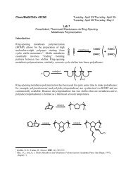
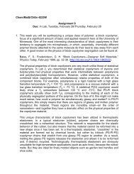
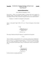
years. Figure 1 shows, for the period between 1970 and<br />
2009, the continuing increase in the number of publications<br />
that could be readily recognized as reporting on the<br />
preparation or use of ionophore-based ISEs. Clearly, this<br />
is still a fast growing field. Until the mid 1990s, most of<br />
the research in this field focused on the development of<br />
new ionophores that provided improved selectivities. 4 However,<br />
many leading analytical chemists who work in the<br />
field have since redirected their attention to an improved<br />
understanding of the thermodynamics and kinetics that<br />
Supramolecular Chemistry: From Molecules to Nanomaterials.<br />
Edited by Philip A. Gale and Jonathan W. Steed.<br />
© 2012 John Wiley & Sons, Ltd. ISBN: 978-0-470-74640-0.<br />
describe the response and selectivity of ISEs, the development<br />
of new sensing modes and electrode designs, as<br />
well as the use of novel materials, such as novel polymer<br />
matrixes, nanostructured materials, or biomaterials.<br />
These efforts resulted in substantial progress, such as the<br />
lowering of detection limits from micro- to subpicomolar<br />
concentrations, 8–16 dramatic improvements of selectivities<br />
up to 10 and more orders of magnitude from<br />
16, 17<br />
what used to be rarely more than five orders of magnitude,<br />
and major advancements in biocompatibility and<br />
long-term stabilities. 5, 18–20 Unfortunately, there has been<br />
no major monograph summarizing the current state of<br />
the art of ISEs to an audience that is new to the field.<br />
Most recent reviews on ISEs are better suited for those<br />
who already have a substantial knowledge of ionophorebased<br />
ISEs and only wish to get an update on recent<br />
advances.<br />
This chapter familiarizes the reader not only with the<br />
state of the art of ISEs, which was achieved by the application<br />
of sophisticated host–guest chemistry, but also with<br />
a modern view of the fundamentals of ionophore-based<br />
ISEs. It introduces the basic concepts of the thermodynamic<br />
ISE theory that has replaced, in recent years, the<br />
empirical approach taken in the early history of ISEs.<br />
This theory provides sophisticated tools to control sensor<br />
selectivities that are not immediately obvious given<br />
the concepts of host–guest chemistry in a homogeneous<br />
phase. A general knowledge of these tools will help the<br />
host–guest chemist to better identify needs and opportunities<br />
for the development of new ionophores, and it<br />
will introduce newcomers to the field of ISEs to fundamentals<br />
and important contributions from the original<br />
literature. The focus of the fundamental section of this<br />
chapter is not on details but on the understanding of major
2540 Supramolecular devices<br />
Number of publications<br />
250<br />
200<br />
150<br />
100<br />
50<br />
0<br />
1970 1975 1980 1985 1990 1995 2000 2005 2010<br />
Year<br />
Figure 1 Number of publications that reported between 1970<br />
and 2009 on the preparation or use of ion-selective electrodes<br />
(ISEs) with an ionophore-doped sensing membrane. Note that the<br />
numbers shown are conservative estimates that are likely too low<br />
because they only include publications that explicitly refer to an<br />
ionophore or carrier.<br />
concepts and the elimination of misconceptions. Only a<br />
minimum number of equations are used, and the interested<br />
reader is referred to the original literature and more<br />
specialized reviews for further reading. For the sake of<br />
simplicity, certain details such as reduced activity coefficients<br />
at higher concentrations, ion pairing effects, and<br />
liquid junction potentials within sandwich membranes have<br />
been omitted here. We believe that such effects go beyond<br />
the scope of this chapter and that the interested reader will<br />
certainly find them discussed appropriately in the original<br />
literature.<br />
Importantly, this chapter shows not only how modern<br />
potentiometry allows the extremely efficient application of<br />
ionophores but also illustrates how ionophore-based potentiometry<br />
can be used to determine thermodynamic properties<br />
of ionophores such as the stoichiometries and stabilities<br />
of their complexes with a wide range of ions. Indeed, it<br />
is still often overlooked that ion-selective potentiometry<br />
with ionophore-doped sensing membranes not only benefits<br />
from ionophores developed by host–guest chemists,<br />
but that it also provides sophisticated methods to characterize<br />
the ion-binding properties of ionophores, polymers,<br />
and other compounds. As several thousand research articles<br />
show, those who practice molecular recognition have been<br />
using pH-selective glass electrodes for more than half a century<br />
to monitor host–guest complexation in the aqueous<br />
phase. 21, 22 However, many researchers practicing outside<br />
of the ISE field have yet to recognize that potentiometry<br />
is also extremely useful to study the host–guest chemistry<br />
of ionophores in the microliter volume of hydrophobic<br />
ISE membranes, using in a very economic fashion only<br />
a few milligrams of ionophore. Therefore, the goal of<br />
this chapter is not only to give a brief history of ISEs<br />
(Section 2), show how host–guest chemistry is used to<br />
design ionophores (Section 4), and use them efficiently in<br />
ISEs (Section 3) but also to illustrate how ionophore-based<br />
ion-selective potentiometry can be used by host–guest<br />
chemists as a tool to investigate host–guest chemistry<br />
(Section 5).<br />
2 ION-SELECTIVE POTENTIOMETRY<br />
MEETS HOST–GUEST CHEMISTRY<br />
The senses are key to life as they permit the perception<br />
of outside stimuli. The commonly cited ones include<br />
hearing, touch, sight, taste, and smell, and allow humans<br />
to obtain physical and chemical information about their<br />
environment. Attempts to use the same principles and<br />
build instrumentation that measures such parameters have<br />
resulted in sensors that measure physical parameters, such<br />
as pressure, temperature, and the intensity of light, as<br />
well as chemical sensors that can be used to measure the<br />
concentration of specific chemical species in air and water.<br />
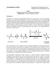
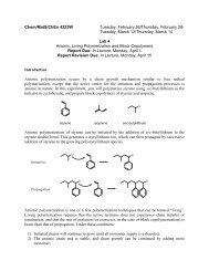
Arguably one of the most successful types of chemical<br />
sensors are ISEs, which can be used to determine the<br />
concentration of selected ions by comparatively simple<br />
measurements of electrical potentials with a voltmeter<br />
(Figure 2).<br />
The history of ISEs goes back all the way to 1906, when<br />
Max Cremer discovered pH-sensitive glasses, 23 which led<br />
to the first commercial pH glass electrodes in the 1930s. 24<br />
The introduction of crystalline compounds such as LaF 3 ,<br />
AgCl, or Ag 2 S as sensing materials in the early 1960s<br />
considerably expanded the number of ions that could be<br />
measured. Among the most notable ISEs of this type are the<br />
fluoride- and halide-selective electrodes. 1 While ISEs based<br />
on glasses and the crystalline materials are extremely useful<br />
for many applications, the further development of ISEs<br />
based on these materials was hindered by the difficulty of<br />
designing crystalline materials with selectivities for particular<br />
ions of interest. Fine tuning of the glass composition<br />
led to the discovery of materials responding to other ions,<br />
such as Li + and Na + , but the selectivities of sensors based<br />
on these glasses remained restricted. 4 Moreover, the use of<br />
crystalline compounds as sensing materials is limited by<br />
the poor ionic conductivity of most crystalline compounds.<br />
However, at a point in time when the further development<br />
of ISEs stalled and it appeared that these sensors were going<br />
to be suitable for the analysis of only a limited number<br />
of chemical species of interest, ISEs based on ion-binding<br />
receptors (i.e., ionophores or ion carriers) were introduced.<br />
This completely transformed the field of ISEs, and was the<br />
onset of a long-lasting impact of host–guest chemistry on<br />
the development of chemical sensors.
<strong>Ion</strong>ophore-doped sensing membranes 2541<br />
(b)<br />
EMF (mV)<br />
(a)<br />
<strong>Ion</strong>-selective<br />
membrane<br />
−7<br />
−6<br />
<strong>Ion</strong>-selective<br />
electrodes<br />
−5<br />
−4<br />
log a I<br />
+<br />
−3<br />
EMF (mV)<br />
−2<br />
59.2 mV<br />
−1<br />
Reference<br />
electrodes<br />
Figure 2 (a) Potentiometric response and (b) experimental<br />
setup in a conventional ion-selective electrode measurement.<br />
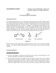
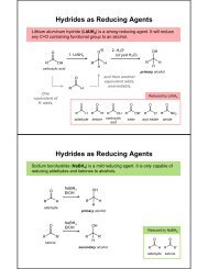
The earliest work with ISEs based on electrically neutral<br />
ionophores was inspired by the observation of Moore and<br />
Pressman that the antibiotic valinomycin (Figure 3), K + -I,<br />
caused the uptake of K + into and the release of H +<br />
from mitochondria. 25 Simon and Stefanac showed in 1966<br />
that thin films of water-immiscible organic solvents doped<br />
with antibiotics exhibited responses to monovalent cations<br />
with selectivities similar to those observed in biological<br />
systems. 3, 26, 27 While the very first examples of such ISEs<br />
used the ammonium-selective receptors nonactin (NH + 4 -I)<br />
and monactin (NH + 4 -II), the ISE based on the antibiotic<br />
valinomycin reported shortly afterwards 28 has become one<br />
of the best known ISEs. The fame of the valinomycinbased<br />
ISE stems from its high K + selectivity, which permits<br />
K + measurements in biological samples, such as blood,<br />
and has made this ISE a commercial success to this<br />
day.<br />
The 1960s were also a period in which the field<br />
of host–guest chemistry made tremendous advances, as<br />
exemplified by the Nobel prize-winning development of<br />
crown ethers. Not surprisingly, both analytical and organic<br />
chemists quickly set out to develop synthetic ionophores<br />
for use in ISEs. The result of this development was that<br />
ion-selective potentiometry replaced flame atomic emission<br />
spectroscopy in the 1980s as the standard technique<br />
for the measurement of electrolyte ions in blood<br />
and urine. Well over a billion measurements are performed<br />
annually with ISEs, making this type of sensor<br />
one of the biggest successes of host–guest chemistry.<br />
4, 29, 30 This is also reflected by the many subject areas<br />
in which articles on ISEs have been published, which<br />
include not only analytical chemistry but also other fields of<br />
chemistry, environmental sciences, medicine, engineering,<br />
O<br />
O<br />
O<br />
O<br />
O<br />
NH<br />
O<br />
NH<br />
O<br />
O<br />
O<br />
N<br />
H<br />
O<br />
H<br />
N<br />
O<br />
O<br />
HN O<br />
O<br />
O<br />
NH<br />
O<br />
O<br />
O<br />
O<br />
O<br />
R2<br />
O<br />
O<br />
R 1<br />
O<br />
O<br />
O<br />
O<br />
R 3<br />
O<br />
O<br />
R 4<br />
O<br />
NH 4 + -I R 1 , R 2 , R 3 , R 4 = CH 3<br />
NH 4 + -II R 1 , R 2 , R 3 = CH 3 ; R 4 = C 2 H 5<br />
O<br />
K + -I<br />
Figure 3 Structures of the three antibiotics valinomycin, nonactin, and monactin, which continue to be widely used as ionophores for<br />
ISE membranes.
2542 Supramolecular devices<br />
pharmacology, biochemistry, food science and technology,<br />
physiology, neurosciences, and agronomy, to name just<br />
a few.<br />
The original development of ionophore-based ISEs, with<br />
an experimental setup strongly resembling the glass electrode,<br />
was followed by the introduction of several related<br />
techniques. Among the earliest ones were microelectrodes<br />
(Section 3.1.6), 31–33 ISEs with integrated enzyme layers,<br />
and ISEs modified with gas-permeable membranes for the<br />
detection of electrically neutral, volatile species such as<br />
ammonia and carbon dioxide (Section 3.1.7). 34 The experimental<br />
limitations associated with the inner filling solution<br />
separating the ion-selective membrane from the inner reference<br />
element inspired several proposals for so-called<br />
solid-contact ISEs (Section 3.1.5). 35–38 Eventually, even the<br />
dogma of using these ionophore-doped ion-selective membranes<br />
in a potentiometric mode, that is, in the absence of<br />
net ionic current, was swept away when ionophores started<br />
39, 40<br />
to be used in ion-transfer voltammetric, galvanostatic,<br />
41, 42 43, 44<br />
and coulometric methods (Section 3.1.8).<br />
Notwithstanding, the general concepts of ionophore-based<br />
potentiometry, as they are discussed in Sections 3 and 5,<br />
are common to all these techniques.<br />
3 A PRIMER TO IONOPHORE-BASED<br />
POTENTIOMETRY<br />
3.1 The origin of the potentiometric response<br />
3.1.1 Phase boundary potentials<br />
Above their detection limit, ISEs respond to ions with<br />
changes in the measured electrical potential, as illustrated<br />
in Figure 2. For historical reasons, the measured potential<br />
is typically referred to as electromotive force, EMF. At<br />
room temperature, a 10-fold increase in the activity of<br />
the ion i with the charge z i results in an increase in the<br />
EMF of 59.2 mV/z i , as predicted for 25 ◦ C by the Nernst<br />
equation 3, 45 :<br />
EMF = E ◦ + RT<br />
z i F ln a i = E ◦ + 2.303RT<br />
z i F<br />
log a i (1)<br />
The term E ◦ is a constant, as will be discussed with more<br />
detail below. The origin of this EMF response is directly<br />
related to the sample dependence of the electrical potential<br />
difference across the phase boundary between the sample<br />
phase and the hydrophobic ion-selective phase. Therefore,<br />
before considering any other experimental aspects, let<br />
us have a closer look at the phase boundary between<br />
ionophore-doped hydrophobic phases and aqueous samples.<br />
While Section 3.1.3 will briefly comment on the role of the<br />
reference electrode and the inner reference element of an<br />
ISE, the following discussion emphasizes that the phase<br />
boundary between the sample phase and the hydrophobic<br />
ion-selective phase is what needs to be considered to<br />
understand why an ISE responds to the ion of interest, and<br />
how the selectivities of ISEs for the target over other ions<br />
can be explained quantitatively.<br />
Phase boundary potentials are much more common than<br />
the nonelectrochemist may suspect, and are quite easy to<br />
understand intuitively. Consider for example, an organic<br />
chemist who is interested in phase transfer catalysis and<br />
uses an extraction funnel filled with equal volumes of<br />
water and a water-immiscible organic solvent (Figure 4).<br />
Upon addition of tetrabutylammonium nitrate and complete<br />
equilibration of the two phases, there will be tetrabutylammonium<br />
nitrate in both phases. Because of the requirement<br />
for electroneutrality in bulk phases, the concentration of<br />
tetrabutylammonium ions (shown in Figure 4 as C + ) in<br />
the aqueous phase will equal the concentration of nitrate<br />
ions (A − ) in the aqueous phase. While the concentration of<br />
tetrabutylammonium ions in the organic phase will differ<br />
from that in the aqueous phase because of the different<br />
energies of tetrabutylammonium nitrate solvation in the<br />
aqueous and organic phase, the tetrabutylammonium ion<br />
concentration in the organic phase will again (because of<br />
bulk electroneutrality) equal the concentration of the nitrate<br />
ions in the bulk of the organic phase. Only in very close<br />
proximity of the phase boundary between the aqueous and<br />
organic phase, the different characters of the two types of<br />
ions will manifest themselves as an imbalance between the<br />
local concentrations of cations and anions. For example,<br />
in the case of 1,2-dichloroethane as the organic phase, the<br />
nitrate ion prefers the aqueous phase. Indeed, the transfer<br />
of nitrate ions from 1,2-dichloroethane into the aqueous<br />
phase is favored by 33.9 kJ mol −1 . 46 On the other hand, the<br />
hydrophobic tetrabutylammonium ion prefers the organic<br />
phase, as shown by the Gibbs energy of partition between<br />
water and 1,2-dichloroethane of −21.8 kJ. 46 The different<br />
affinities of the two ions for the two phases result in charge<br />
separation across the interface between the aqueous and<br />
organic phases. While there will be a small excess of negative<br />
nitrate ions on the aqueous side of the interface, there<br />
will be a small excess of positive tetrabutylammonium ions<br />
on the organic side of the interface. This interfacial charge<br />
separation is the origin of the interfacial phase boundary<br />
potential. In Figure 4, the thin interfacial region in which<br />
charge separation occurs is schematically shown as the<br />
region between the two dashed red lines. In full consistency<br />
with electroneutrality, the excess of positive ions on<br />
one side of the phase boundary equals the excess of negative<br />
ions on the other side of the phase boundary.<br />
A considerable amount of research has been performed to<br />
investigate the structure of such interfaces at the molecular
<strong>Ion</strong>ophore-doped sensing membranes 2543<br />
[C + A − ] org<br />
(a)<br />
[C + A − ] aq<br />
C + C + A −<br />
A −<br />
C + C +<br />
C + A −<br />
Organic phase<br />
(bulk)<br />
C + C + C +<br />
A − A − A −<br />
A − A − C + A − C + A −<br />
A − A − A − C<br />
C + +<br />
C +<br />
Charge separation<br />
layer (nm dimension)<br />
Aqueous phase<br />
(bulk)<br />
(b)<br />
Figure 4 Equilibrium distribution of a single salt with the cations C + and anions A − between an aqueous and a water-immiscible<br />
organic phase: The ratio of the salt concentrations in the two phases is given by the distribution coefficient. Charge separation occurs<br />
across the phase boundary but there is electroneutrality in both bulk phases.<br />
level, for example, in order to determine how sharp the<br />
transition from water to the organic solvent is and how<br />
ions distribute spatially within the charge separation layer. 47<br />
Not surprisingly, there are differences for different solvents<br />
and ions, and the concentrations of the involved salts play<br />
an important role too. In order to understand the response<br />
mechanism of an ionophore-based ISE, such details are<br />
luckily irrelevant. The only important information for an<br />
intuitive understanding of phase boundary potentials is that<br />
the thickness of the charge separation layer within which<br />
electroneutrality can be violated is only on the order of<br />
nanometers. 47<br />
The above description of the phase boundary between an<br />
aqueous and an organic salt solution readily permits an intuitively<br />
easily understandable conclusion: the phase boundary<br />
potential depends on the type of ions involved. Consider,<br />
for example, the interface between an aqueous and an<br />
organic phase both containing tetrabutylammonium nitrate,<br />
and compare it to the interface between an aqueous and an<br />
organic phase containing the nitrate salt of tetrapropylammonium,<br />
which has a total of four methylene groups less.<br />
The phase boundary potential at the former interface will<br />
be larger than at latter interface since the preference of the<br />
tetrapropylammonium ion for the organic phase is smaller<br />
than it is in the case of the tetrabutylammonium ion. For the<br />
case of the organic solvent 1,2-dichloroethane, for example,<br />
the Gibbs free energy of partition of the tetrapropylammonium<br />
ion is only −8.8 kJ mol −1 , which is much smaller than<br />
the value of −21.8 kJ mol −1 for the tetrabutylammonium<br />
ion. 46<br />
A somewhat less intuitive fact is that the phase boundary<br />
potential at the interface between two phases that contain<br />
only one salt (the so-called distribution potential) does not<br />
depend on concentration of this salt (unless its concentration<br />
is so high that activity coefficients differ substantially from<br />
unity). 48 On a qualitative level, this may be understood by
2544 Supramolecular devices<br />
the fact that any concentration-induced increased tendency<br />
of the nitrate to transfer from the organic into the aqueous<br />
phase is countered by an equivalent concentration-induced<br />
increase in the tendency for the tetraalkylammonium ion<br />
to follow nitrate into the aqueous phase, and vice versa.<br />
From the view of thermodynamics, the concentration independence<br />
of the phase boundary potential in this particular<br />
case can be explained quantitatively with a very general<br />
equation that describes the phase boundary potential, E PB ,<br />
at equilibrium:<br />
E PB = E ◦ PB,i + RT<br />
z i F ln a i,water<br />
a i,organic<br />
(2)<br />
where E ◦ PB,i<br />
is a constant that depends on the solvation<br />
energies of the ion i in the two phases. The derivation of this<br />
equation from electrochemical potentials is straightforward,<br />
as shown in the literature. 3, 45, 49 Clearly, as long as the<br />
addition of more salt into the two-phase system raises the<br />
activities of the ion i in both phases by the same factor, the<br />
phase boundary potential, E PB , does not depend on the salt<br />
concentration.<br />
In the case of one or multiple salts distributing between<br />
two immiscible liquids, E ◦ PB,i<br />
is different for every ion<br />
involved since this value depends on ionic solvation.<br />
However, since there is only one physical phase boundary,<br />
there is also only one value for the phase boundary<br />
potential, E PB , between the two phases. In the example of<br />
the single salt distributing between the two phases, the same<br />
value of E PB is obtained when (2) is applied to the cation<br />
as when it is applied to the anion, which can be understand<br />
upon realizing that the charge z i of the two ions differ.<br />
3.1.2 Essential components of an ionophore-doped<br />
ISE membrane: ionophore and ionic sites<br />
Equation (2) for the phase boundary potential applies<br />
not only to distribution potentials but can be used for<br />
any number of ions that are distributed between two<br />
immiscible solutions. Most importantly, it applies to the<br />
sample–membrane interface of any type of ISE. Indeed,<br />
one of the most fundamental principles of ISEs can be<br />
directly obtained by rearrangement of (2). If the activity<br />
of the ion of interest in the bulk of the water-immiscible<br />
sensing phase is constant and does not depend on the<br />
sample, the phase boundary potential at the interface of<br />
the sample and an ionophore-doped hydrophobic phase has<br />
the same dependence on the ion activity as the desirable<br />
Nernstian response of an ISE (1) 50 :<br />
E PB = E ◦ PB,i + RT<br />
z i F ln a i,water + RT<br />
z i F ln 1<br />
a i,organic<br />
= E ◦ ′<br />
PB,i + RT<br />
z i F ln a i,water (3)<br />
The two key tasks for the scientist who fabricates and<br />
uses an ISE are (1) to assure that the activity of the ion of<br />
interest in the bulk of the water-immiscible sensing phase<br />
is constant and does not depend on the sample composition,<br />
and (2) to ensure that, except for E PB , all contributions to<br />
the measured EMF are sample independent (for the latter,<br />
see Section 3.1.2). If these two requirements are fulfilled,<br />
an ISE will respond to the ion of interest with the desired<br />
Nernstian response.<br />
To illustrate which components are necessary to prepare<br />
an ISE membrane, let us again go back to a simple<br />
extraction experiment as it was similarly described in<br />
Section 3.1.1. Consider an aqueous potassium chloride<br />
solution equilibrated with an immiscible organic phase<br />
containing an electrically neutral ionophore for K + ,that<br />
is, a receptor compound that binds the potassium ion<br />
selectively. How does the phase boundary potential between<br />
these two phases depend on the KCl concentration in the<br />
aqueous phase Upon equilibration of the two phases, some<br />
KCl will be present in the organic phase (Figure 5). For<br />
low amounts of KCl in the system, the potassium ions in<br />
the organic phase will be present in the form of ionophore<br />
complexes, and there will be an excess of free ionophore,<br />
L. In comparison to the concentration of the ionophore<br />
complex, the organic phase concentration [K + ] of free<br />
potassium ions that are not bound by the ionophore is very<br />
low and can be calculated from the formation constant, β 1:1 ,<br />
of the potassium ion complex, [LK + ]:<br />
β 1:1 = [LK+ ]<br />
[L][K + ] ⇒ [K+ ] = [LK+ ]<br />
[L]β 1:1<br />
(4)<br />
The higher the KCl concentration in the aqueous phase<br />
is, the higher the complex concentration and the lower<br />
the concentration of free ionophore in the organic phase<br />
becomes. Consequently, the ratio of free and complexed<br />
ionophore changes and, as shown by (4), the free potassium<br />
concentration in the organic phase depends on the activity<br />
of the potassium ions in the aqueous phase. Indeed, for an<br />
excess of ionophore, the concentration of free potassium<br />
ions in the organic phase is directly proportional to the<br />
activity of the potassium ions in the aqueous phase,<br />
and it follows from (2) that in this range the phase<br />
boundary potential does not depend on the potassium ion<br />
concentration in the aqueous phase. The E PB obtained<br />
under these circumstances is again a distribution potential<br />
(Section 3.1.1) independent of the salt concentration in the<br />
aqueous phase. However, this phase boundary potential<br />
differs from the one in the absence of ionophore because<br />
the excess ionophore facilitates the phase transfer of<br />
the potassium ion into the organic phase and, therefore,<br />
considerably increases the total concentration of KCl in the<br />
organic phase. Importantly, because of the independence
<strong>Ion</strong>ophore-doped sensing membranes 2545<br />
[K + Cl − ] org<br />
(a)<br />
[K + Cl − ] aq<br />
<strong>Ion</strong>ophore<br />
complex<br />
Free<br />
ionophore<br />
K + Cl −<br />
K + Cl − Cl − Organic phase<br />
(bulk)<br />
Cl −<br />
K +<br />
K +<br />
K + Cl − K +<br />
Cl − K + Charge separation<br />
Cl − layer (nanometer dimension)<br />
Cl − Cl − K +<br />
K + Cl − K + K + Cl − Aqueous phase<br />
Cl − K<br />
K + +<br />
Cl −<br />
(bulk)<br />
K + Cl −<br />
(b)<br />
Figure 5 Equilibrium distribution of KCl between an aqueous phase and a water-immiscible organic phase that contains a K + -binding<br />
ionophore. The ionophore increases the solubility of the salt in the organic phase.<br />
of this phase boundary potential on the K + concentration<br />
in the aqueous phase, it cannot be the basis of the<br />
sample dependent EMF of an ISE. Simply doping a waterimmiscible<br />
organic thin film with ionophore does not make<br />
an ion-selective membrane suitable for potentiometry. 51<br />
The trick necessary to keep the activity of the ion<br />
of interest in the bulk of the water-immiscible sensing<br />
phase sample-independent is to add to the organic phase<br />
in addition to the electrically neutral ionophore also a<br />
hydrophobic ion that has a charge sign opposite to the<br />
charge sign of the measured ion (Figure 6). In the example<br />
of a K + ionophore, such an ion could be, for example,<br />
a tetraphenylborate derivative (Figure 7). Owing to the<br />
requirement of electroneutrality, the total concentration of<br />
(free and complexed) potassium ions in the bulk of the<br />
organic phase equals the concentration of all anions in this<br />
phase. As long as the hydrophobic anion is the only anion<br />
present in the organic phase at a substantial concentration,<br />
the K + concentration in the organic phase does not depend<br />
on the KCl concentration in the aqueous phase, and it<br />
follows from (3) that E PB shows a Nernstian dependence<br />
on the potassium ion activity in the aqueous sample. 52<br />
Importantly, the hydrophobic anion suppresses the extraction<br />
of chloride into the organic phase, as can be seen from<br />
the equilibrium constant K ex that governs the distribution<br />
of KCl between the two phases.<br />
K + aq + Cl− aq −−−−⇀ ↽−−−− K + mem + Cl− mem<br />
K ex = a K + , mem a Cl − , mem<br />
a K + , aq a Cl − , aq<br />
(5a)<br />
(5b)<br />
In the absence of a hydrophobic anion in the organic<br />
phase, the concentrations of K + and Cl − in the organic<br />
phase are equal. However, when the concentration of K +<br />
in the organic phase is very high because these ions balance<br />
the negative charge of the hydrophobic counteranions<br />
(R − ), the consequence of (5b) is that a Cl − , mem becomes<br />
very low. This can be considered to be a Le Chatelier effect<br />
on the KCl distribution between the two phases (5a); a high
2546 Supramolecular devices<br />
−2<br />
LK +<br />
−4<br />
Cl −<br />
−6<br />
K +<br />
−8<br />
−10<br />
2<br />
−6 −4 −2 0 2<br />
(a)<br />
log a KCl, aq<br />
100<br />
50<br />
0<br />
59.2 mV<br />
−50<br />
−6 −4 −2 0 2<br />
(b)<br />
log a KCl, aq<br />
K + K R − + R − Organic phase<br />
K +<br />
(bulk)<br />
K +<br />
R −<br />
R − K + Charge separation<br />
Cl − K +<br />
Cl − K +<br />
Cl − layer (nanometer dimension)<br />
Cl − Cl − K +<br />
K +<br />
Cl − K + K + Cl − Cl − K<br />
K + + Aqueous phase<br />
Cl − K + Cl −<br />
(bulk)<br />
log c org<br />
Phase boundary potential (mV)<br />
(c)<br />
Figure 6 Equilibrium ion distribution between an aqueous KCl solution and a water-immiscible sensing phase doped with a K +<br />
ionophore (L) and anionic sites (R − ): The phase boundary potential at the interface of the aqueous and organic phase is the origin of<br />
the familiar Nernstian response of ISEs. Note that within the Nernstian response range the Cl − concentration in the organic phase is<br />
extremely small, and the vast majority of K + in the membrane is in the complexed form.<br />
concentration of K + in the organic phase favors chloride<br />
transfer into the aqueous phase.<br />
In the older potentiometric literature hydrophobic ions<br />
used as counterions to the analyte ion have been sometimes<br />
referred to as ion excluders. In the current literature, they<br />
are typically referred to as ionic sites. It follows from the<br />
discussion above that ionic sites are a necessity for the<br />
proper functioning of ISEs based on electrically neutral<br />
ionophores. 51 <strong>Ion</strong>ic sites are not required to ensure that<br />
ISE membranes doped with electrically charged ionophores<br />
exhibit a Nernstian response to the ion of interest, but as it<br />
is also true for the electrically neutral ionophores, ionic sites
<strong>Ion</strong>ophore-doped sensing membranes 2547<br />
Cl<br />
F 3 C<br />
CF 3<br />
Cl<br />
CF 3<br />
Cl<br />
B<br />
Cl<br />
F 3 C<br />
F 3 C<br />
B<br />
CF 3<br />
N +<br />
CF 3<br />
CF 3<br />
Figure 7<br />
Common highly hydrophobic ionic sites used to dope ISE membranes.<br />
Membrane<br />
Sample<br />
R − R − R − R − R − R −<br />
K + K + K + K +<br />
K + K +<br />
K + Cl − K + Cl −<br />
(a)<br />
(b)<br />
Figure 8 Equilibrium ion distribution between an aqueous KCl solution and an ISE membrane with a ratio of K + ionophore and<br />
cationic sites of (a) 1 : 2, and (b) 2 : 1.<br />
used in an optimized ratio to the ionophore can improve the<br />
selectivity (Section 5.2). 53<br />
Note that the concentration of ionic sites has to be low<br />
enough so that the organic phase contains a substantial<br />
concentration of free ionophore. For example, consider an<br />
organic phase prepared to contain an anionic site and an<br />
electrically neutral ionophore that binds K + with 1 : 1 stoichiometry.<br />
If the molar ratio of ionic sites and ionophore<br />
is 2 : 1 and the organic phase is equilibrated with an aqueous<br />
KCl solution, all of the ionophore will be present in<br />
the form of K + complexes, and only half of the K + ions<br />
will be able to bind to an ionophore (Figure 8a). Because<br />
of the very substantial concentration of uncomplexed K +<br />
in the organic phase, the phase boundary potential will be<br />
identical to the one observed for an ionophore-free organic<br />
phase containing only ionic sites. On the other hand, if the<br />
molar ratio of ionic sites and ionophore is 1 : 2 and the<br />
organic phase is equilibrated with an aqueous KCl solution,<br />
half of the ionophore will be present in the form of<br />
K + complexes, half of the ionophore is in its uncomplexed<br />
form (Figure 8b), and the phase boundary potential exhibits<br />
the selectivity characteristic for an ionophore-doped organic<br />
phase. This latter situation is similar to the one of pH<br />
buffers, which only exhibit good buffering capacities if they<br />
contain substantial concentrations of both an unprotonated<br />
base and the conjugated acid (i.e., the proton complex of<br />
the conjugated base). Following this analogy, we can simplify<br />
the above statement that “a Nernstian ISE response<br />
requires that the activity of the ion of interest in the bulk<br />
of the water-immiscible sensing phase is constant and does<br />
not depend on the sample.” More succinctly, a Nernstian<br />
ISE response requires that the ionophore and the ionic sites<br />
buffer the ion of interest in the sensing phase.<br />
3.1.3 The conventional ISE measurement<br />
As shown above, the phase boundary potential at the<br />
interface between an aqueous sample and the hydrophobic<br />
sensing phase of an ISE membrane depends logarithmically<br />
on the activity of the ion of interest in the aqueous<br />
sample (3). However, an experimental method to measure<br />
this phase boundary potential directly does not exist. The<br />
reason why potentiometric measurements, nevertheless,<br />
exhibit the same logarithmic dependence on the activity of<br />
the ion of interest in the sample is illustrated in Figure 9.<br />
The actual potentiometric measurement determines the<br />
EMF as the difference in the electrical potentials between<br />
the connecting wire of the ISE and the connecting wire<br />
of a reference electrode. As in every electrochemical<br />
cell, the EMF is the sum of two types of components:<br />
One type of contributions to the measured EMF arises<br />
from the phase boundary potentials at all interfaces of<br />
the electrochemical cell. Figure 9 illustrates the various<br />
phase boundary potentials present along the path from the<br />
copper connector of a typical ISE through the selective<br />
electrode, the sample, and the reference electrode. These<br />
phase boundary potentials include interfaces of different<br />
types, such as metal–metal, metal–salt, salt–liquid, and<br />
liquid–liquid interfaces. The other types of components<br />
that contribute to the measured EMF of an electrochemical
2548 Supramolecular devices<br />
<strong>Ion</strong>-selective<br />
electrode<br />
EMF<br />
Reference<br />
electrode<br />
Ag/AgCl<br />
Inner filling<br />
solution<br />
Reference electrolyte<br />
<strong>Ion</strong>-selective<br />
membrane<br />
Sample<br />
Bridge electrolyte<br />
Capillary<br />
E<br />
Profile of electrical potential, EMF: a sum of phase boundary potentials<br />
The only sample-dependent<br />
phase boundary potential (ideally)<br />
EMF<br />
Cu Ag AgCl KCl LiOAc Sample <strong>Selective</strong><br />
aqueous aqueous membrane<br />
KCl AgCl Ag Cu<br />
aqueous<br />
Figure 9 In the ideally currentless potentiometric measurement with an ISE, the measured potential is the sum of the all phase<br />
boundary potentials.<br />
cell are associated with ohmic drop, V ohm . The latter is<br />
the potential difference between the two ends of any ionic<br />
or electric conductor with resistance R when an electrical<br />
current, i, flows through it. It can be readily calculated as<br />
Ri, but since ion-selective potentiometry is almost always<br />
performed under nearly perfectly currentless conditions, the<br />
ohmic drop in an ISE measurement is negligibly small.<br />
Consequently, the EMF in a potentiometric measurement<br />
equals the sum of all phase boundary potentials, as they<br />
are illustrated in Figure 9.<br />
Importantly, only two phase boundary potentials arise at<br />
interfaces between the sample and a neighboring phase and,<br />
consequently, all but those two phase boundary potentials<br />
add up to one sample-independent term, E const :<br />
EMF = ∑ E PB<br />
=E const + E PB(salt bridge/sample) + E PB(sample/ISE membrane)<br />
≈ E ′ const + E PB(sample/ISE membrane) (6)<br />
Indeed, by choosing an appropriate electrolyte of high<br />
concentration for the salt bridge separating the sample from<br />
the reference electrode (lithium acetate in the example<br />
of Figure 9), the phase boundary potential at the salt<br />
bridge/sample interface can be kept very small and sample<br />
independent. 1, 54 The only remaining phase boundary potential<br />
that is not included in the constant term is the phase<br />
boundary potential between the aqueous sample and the<br />
ionophore-doped sensing phase, which explains the logarithmic<br />
dependence of the EMF on the sample activity.<br />
In the classical ISE setup, the ionophore-doped hydrophobic<br />
sensing phase separates the sample from the inner filling<br />
solution of the selective electrode. It is typically referred to<br />
as ion-selective membrane, a term that should, however, be<br />
interpreted with care. In most other applications of membranes,<br />
such as in filtration, osmosis, electrolysis, and gas<br />
separation, selective transport through the membrane is a<br />
key requirement and high transmembrane fluxes are very<br />
desirable. The complete opposite is true for ISE membranes.<br />
While ion movements over nanometers within the charge<br />
separation layer at the phase boundary between the sample<br />
and the membrane phase are key to the establishment<br />
of the ISE response, net ion transport through ISE membranes<br />
is not a requirement for the ISE response. Quite<br />
to the contrary, net fluxes of the ions of interest between<br />
the sample and the inner filling solution of an ISE worsen
<strong>Ion</strong>ophore-doped sensing membranes 2549<br />
EMF (mV)<br />
59.2 mV<br />
(a)<br />
−12<br />
−11.5 −11 −10.5 −10 −9.5 −9 −8.5<br />
log a Ag<br />
+<br />
Sample phase<br />
Membrane phase<br />
Inner filling phase<br />
I +<br />
LI + R − I +<br />
Nernstian<br />
layer, d<br />
I + layer, d<br />
I + I +<br />
Nernstian<br />
Thickness<br />
Concentration of I +<br />
(b)<br />
Figure 10 (a) Parts per trillion (ppt) detection limit for Ag + achieved by suppression of net ion fluxes. (Reproduced from Ref. 16. ©<br />
ACS, 2010.) (b) Schematic illustration of how the flux of the target ion I + from the inner filling solution of an ISE through the sensing<br />
membrane into the sample can contaminate samples, worsening potentiometric detection limits.<br />
detection limits (Figure 10). Indeed, the discovery of this<br />
phenomenon and the subsequent development of techniques<br />
to suppress such ion fluxes in the late 1990s allowed to<br />
lower the detection limits of ionophore-based ISEs from the<br />
micromolar to nano- and picomolar range. 8–16 The detection<br />
limit is also the only key performance characteristic<br />
for which the thickness of the ISE membrane is relevant.<br />
While the membrane thickness has no direct effect on the<br />
selectivity and response time of an ISE, thinner membranes<br />
increase the (typically extremely low) transmembrane ion<br />
fluxes and worsen detection limits.<br />
Because potentiometric responses only require ion movements<br />
over nanometers at the phase boundary of the sample<br />
and the ion-selective membrane, ISEs have inherently very<br />
fast response times. <strong>With</strong> special equipment that permitted<br />
extremely fast sample exchange, response times of the<br />
order of microseconds have been demonstrated. 55 Response<br />
times of several seconds as they are often observed in routine<br />
measurements should not be misinterpreted as inherent<br />
characteristics of the electrode membrane. They are typically<br />
not related to properties of the ISE membrane itself<br />
but rather to how quickly the unstirrable layer of sample<br />
adhering to the ISE membrane can be exchanged for a new<br />
sample.<br />
Because ISE responses do not depend on any type of ion<br />
current or flux, they are much less affected by adsorption<br />
of contaminants onto the sensor membrane than most other<br />
electrochemical and optical sensors. As long as adsorbed<br />
contaminants do not completely cover the ISE membrane,<br />
they have no effect on the measured response. However, in<br />
contrast to sensors based on solid sensing phases, such as<br />
metals in voltammetric sensors or inorganic salts in solidstate<br />
ISEs, extraction of hydrophobic sample components<br />
into the hydrophobic sensing membranes of ionophoredoped<br />
ISEs can result in the deterioration of the ISE<br />
selectivity. 56 This is of particular concern in the case of<br />
long-term measurements in biological samples.<br />
3.1.4 Polymeric phases as inert matrixes for the<br />
ion-selective membrane<br />
In the above examples, the ionophore-doped ion-selective<br />
membranes have been referred to as a hydrophobic phases.<br />
Historically, the earliest examples of such membranes<br />
were prepared as ionophore solutions in an organic waterimmiscible<br />
solvent infused into some type of porous<br />
support, such as a porous glass filter. In 1970, polymeric<br />
membrane matrixes were introduced to improve the
2550 Supramolecular devices<br />
Cl<br />
PVC<br />
O<br />
N<br />
H<br />
n<br />
N<br />
H<br />
O<br />
O<br />
Si n<br />
Silicone<br />
rubber<br />
O<br />
Polyurethane<br />
O<br />
n<br />
F 3 C<br />
O<br />
O<br />
F<br />
n<br />
O<br />
Polyacrylate<br />
CF 3<br />
O F F<br />
m<br />
F<br />
n<br />
F F 87% Dioxole<br />
Teflon AF2400<br />
Figure 11 Polymer matrixes used to prepare ion-selective electrode<br />
membranes.<br />
mechanical stability, and in particular, resistance to external<br />
pressure, of such devices. 57 While poly(vinyl chloride)<br />
(PVC) continues to be the most common matrix polymer<br />
for ISE membranes, 58, 59 many other polymers have been<br />
successfully used (Figure 11). They include silicone rubbers,<br />
polyurethanes, acrylates, perfluoropolymers, and many<br />
others. 3 It is important that in all these cases, the polymers<br />
do not form any type of channels or have any other<br />
three-dimensional architecture. Instead, the ideal polymer<br />
provides a rubberlike homogenous hydrophobic medium in<br />
which the ionophore, ionophore complexes, and ionic sites<br />
can move freely, as they can do it in a water-immiscible<br />
organic solvent. However, to be able to function properly<br />
as an ISE membrane matrix, a polymer must fulfill a number<br />
of requirements, which will be briefly explained in the<br />
following paragraphs.<br />
Because the sample-dependent phase boundary potential<br />
can only establish if the ions of interest can move freely<br />
back and forth between the aqueous sample and the membrane<br />
phase, crystalline polymers and amorphous polymers<br />
that form hard and brittle glasses at room temperature are<br />
not suitable as ISE membrane matrixes. Many successful<br />
polymers are soft and rubberlike amorphous materials that<br />
only transform into a glassy state well below room temperature.<br />
Others, such as poly(vinyl chloride) or Teflon AF,<br />
have a glass transition temperature that is high, but can be<br />
lowered below room temperature by blending with plasticizers.<br />
60–62 The latter are liquids that are fully miscible with<br />
the polymer, have much lower molecular weights than the<br />
polymer itself, but have sufficiently low vapor pressures so<br />
that evaporation during the use of the ISE is not a concern<br />
(Figure 12). Plasticizers are not only components of many<br />
ISE membranes, but are used in many polymeric consumer<br />
products.<br />
NO 2<br />
O<br />
o-NPOE<br />
O<br />
O<br />
P<br />
O<br />
O<br />
O<br />
O<br />
O<br />
O<br />
DOP<br />
TEHP<br />
Cl<br />
Cl<br />
Cl<br />
Cl<br />
Cl<br />
Cl<br />
Cl<br />
Chloroparaffin<br />
Cl<br />
O<br />
O<br />
O<br />
O<br />
DOS<br />
Figure 12<br />
Plasticizers used for the preparation of ISE membranes.
<strong>Ion</strong>ophore-doped sensing membranes 2551<br />
(a)<br />
(c)<br />
S<br />
N<br />
N H<br />
H<br />
(b)<br />
N<br />
H<br />
N<br />
S<br />
This is often also accompanied by typically minor but sometimes<br />
larger changes in selectivity. 1, 3 If a different polymer<br />
or a different blend of polymer and plasticizer that dissolves<br />
the ion-selective components better cannot be found, the<br />
more cumbersome approach of synthesizing a more soluble<br />
compound has often to be taken. This may involve the<br />
attachment of unbranched or branched alkyl substituents to<br />
the ionophore or ionic site, or the reduction of compound<br />
symmetry. Alternatively, the ion-selective components may<br />
be covalently attached to the polymer backbone. 64<br />
To form a hydrophobic membrane suitable for use in<br />
potentiometry, a polymer cannot have that many polar<br />
groups that it becomes soluble in water. Even for a polymer<br />
of negligible solubility in water, polar substituents can be a<br />
disadvantage, though. In an ideal ISE membrane, the ion of<br />
interest is bound selectively by the ionophore, and any other<br />
type of ion undergoes only minimal stabilizing interactions<br />
with the membrane components. Evidently, after spending<br />
a lot of effort to design ionophores that strongly bind the<br />
ion of interest and form no or only very weak complexes<br />
with other ions, it is not desirable if other (potentially<br />
interfering) ions bind to the polymer or plasticizer, lowering<br />
the selectivity of the ISE membrane. 62 From this point of<br />
view, membrane matrixes of low polarity are desirable. The<br />
ultimate limit of selectivity may arguably be reached with<br />
fluorous matrixes, which are the least polar of all known<br />
condensed phases. Indeed, fluorous membrane ISEs have<br />
16, 65–67<br />
shown exceptional selectivities.<br />
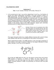
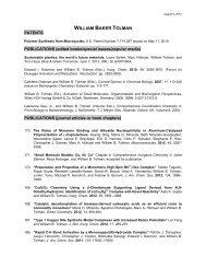
Figure 13 <strong>Ion</strong>ophore aggregation in ISE membranes: Dark<br />
field microscopy images of membranes containing a bis-thiourea<br />
ionophore (c) and 0 or 50 mol% cationic sites (a and b, respectively)<br />
after exposure of the membranes to aqueous sulfate solutions.<br />
(Reproduced from Ref. 63. © Wiley-VCH, 2005.)<br />
The matrix formed by the polymer or the blend of polymer<br />
and plasticizer must dissolve all the components that<br />
provide the ISE membrane with selectivity, that is, the free<br />
ionophore, the ionophore complex, and the ionic sites. In<br />
the case of an electrically neutral ionophore, this means that<br />
precipitation of not only the ionophore itself but also salts<br />
formed by the ionic sites and the ionophore complex must<br />
be avoided. In the laboratory, the formation of crystalline<br />
precipitates is often readily recognized with the naked eye.<br />
Because the aggregation of membrane components can also<br />
result in small crystals or noncrystalline aggregates that may<br />
be easily overlooked, the routine observation of ISE membranes<br />
containing new ionophores or ionic sites with an<br />
optical microscopy is recommended (Figure 13). 63 When<br />
a new ionophore or ionic site has been synthesized but is<br />
found to be affected by solubility problems, a very simple<br />
approach to deal with this problem is to choose a different<br />
polymeric matrix with which precipitation can be avoided.<br />
3.1.5 ISEs with internal solid contacts<br />
The conventional ISE setup with an inner filling solution<br />
separating the ion-selective membrane from an internal reference<br />
such as a AgCl-coated silver wire is very versatile<br />
and can be easily set up in the laboratory, it but brings<br />
along a number of disadvantages. These include insufficient<br />
resistance toward high pressure as encountered in sterilization<br />
and deep-sea measurements, and frailty of miniaturized<br />
sensors due to evaporation of the inner filling solution<br />
or occurrence of osmotic pressure differences across the<br />
ion-selective membrane. The latter is a major factor limiting<br />
the miniaturization of ISEs. Moreover, transmembrane<br />
ion fluxes worsen detection limits and can only be suppressed<br />
with careful optimization. Not surprisingly, various<br />
efforts to eliminate the inner filling solution have been<br />
made and are briefly described in the following paragraphs<br />
to highlight the close relationship of the resulting devices<br />
to conventional ISEs (Figure 14). However, it needs to be<br />
emphasized that these solid-contact devices owe their function<br />
to exactly the same control of the sample–membrane<br />
phase boundary potential using ionophores and ionic sites as<br />
the conventional ISEs with an inner filling solution. While<br />
solid contacts have the promise to significantly enhance the
2552 Supramolecular devices<br />
Coated wire<br />
Conducting polymer<br />
Wire<br />
Wire<br />
<strong>Ion</strong>-selective<br />
membrane<br />
(a)<br />
(b)<br />
Conducting<br />
polymer<br />
<strong>Ion</strong>-selective<br />
membrane<br />
<strong>Ion</strong>-sensitive field effect transistor (ISFET)<br />
SiO 2<br />
<strong>Ion</strong>-selective membrane<br />
Hydrogel<br />
n-type Si<br />
n-type Si<br />
p-type Si<br />
(c)<br />
Figure 14<br />
Potentiometric sensors with different types of internal solid contact.<br />
reliability and extend the number of application fields of<br />
ionophore-based potentiometry, their use does not require<br />
any different host–guest chemistry than conventional ISEs.<br />
In attempts already made in the early 1970s, the ionselective<br />
polymeric membrane was directly applied to<br />
a metal wire. 35 From a theoretical point of view, this<br />
is an unsatisfactory situation because in all but a few<br />
exceptions these membranes contain neither a redox-active<br />
cation of the metal of which the wire is made nor an<br />
electron acceptor/donor pair that determines the redox<br />
potential. As a result, the phase boundary potential at<br />
the membrane/metal interface of most coated-wire ISEs is<br />
poorly defined. It is still not well understood why in real life<br />
freshly prepared coated-wire electrodes sometimes perform<br />
surprisingly well under circumstances when they can be<br />
recalibrated relatively frequently. However, formation of<br />
a water layer at the metal–membrane interface leads<br />
eventually to memory effects and, after delamination of the<br />
sensitive membrane, to catastrophic failure.<br />
Another approach to eliminate the inner filling solution<br />
of conventional ISEs was introduced also in the 1970s<br />
and is based on the use of field effect transistors (FETs).<br />
These devices are referred to as ISFETs, that is, ionsensitive<br />
FETs,<br />
7, 68, 69<br />
and belong together with enzyme<br />
FETs (EnFETs) and gas sensitive FETs to the larger category<br />
of ChemFETs (chemically sensitive FETs). In the case<br />
of the ISFET, the ISE membrane is applied to the Si 3 N 4<br />
surface of a FET, which itself is well known to be H + sensitive.<br />
Considerable efforts have been spent on the fabrication<br />
of hydrogel layers between the selective membrane and the<br />
FET to obtain a reproducible and stable electrode response.<br />
However, ISFETs with ionophore-doped membranes have<br />
never become a major product on the market, which appears<br />
to be mostly explained by the difficulties in controlling the<br />
hydrogel layer and preventing the ion-selective membranes<br />
from pealing off.<br />
The realization that the interface between the ionselective<br />
membrane and the solid contact needs to have<br />
a well-controlled phase boundary potential led in the early<br />
1990s to the introduction of electronically conducting polymers<br />
as an electronically and ionically conducting interlayer<br />
between the ionophore-doped polymeric membrane<br />
and the underlying metal or graphite electrode. 36, 70 Even<br />
though solid-contact ISEs with conducting polymer interlayers<br />
have not yet solved all problems of long-term stability,<br />
they can be considered a considerable success, are<br />
relatively easy to prepare, and have recently been shown to<br />
permit measurements with extremely low detection limits. 7<br />
The latter can be explained by the elimination of transmembrane<br />
ion fluxes. As a result, an increasing number<br />
of research groups have been using this approach over the<br />
first decade of this century, which stands in marked contrast<br />
to the 1980s and 1990s, when only a limited number<br />
of research groups worked with solid-contact ISEs.
<strong>Ion</strong>ophore-doped sensing membranes 2553<br />
An even newer approach to solid-contact ISEs is based on<br />
carbon materials with very large surface area, that is, three<br />
16, 38<br />
dimensionally ordered macroporous (3DOM) carbon<br />
or carbon nanotubes 37 (Figure 15). Here, the ion-selective<br />
membrane is directly infused into the carbon material. It has<br />
been shown that an extremely large surface between the two<br />
materials results in a very large interfacial capacitance, 71<br />
which makes it very hard to polarize this interface. This<br />
appears to explain the outstanding long-term stabilities of<br />
ISE responses measured with 3DOM carbon solid contacts,<br />
which have been found to be of the order of 10 µV h −1 . 38<br />
(a)<br />
(b)<br />
1 µm<br />
Figure 15 (a) Scanning electron microscopy image of 3DOM<br />
carbon 71 (Reproduced from Ref. 71. © ACS, 2010.) and<br />
(b) schematic representation of a carbon nanotube.<br />
3.1.6 <strong>Ion</strong>-selective microelectrodes<br />
The desire to miniaturize ISEs arises from two very different<br />
motivations. On one hand, miniaturized ISEs may be<br />
mass manufactured, lowering the cost and thereby enabling<br />
sensor networks. On the other hand, miniaturized ISEs can<br />
be used to measure in very small volumes. Examples for the<br />
latter include measurements in impaled biological cells, 33<br />
in the eluent coming from a chromatographic column or<br />
electrophoresis capillary, 72 and in close proximity to the<br />
surface of various materials.<br />
The earliest type of ionophore-based potentiometric<br />
microelectrodes were prepared in the mid 1970s from<br />
micrometer-sized glass pipettes, filled at the end with the<br />
ionophore-doped hydrophobic phase (Figure 16). 73, 74 For<br />
speciality applications, in particular, in biochemical and<br />
medical research, these microelectrodes continue to have<br />
a variety of applications. Particularly noteworthy are their<br />
use to study intracellular ion concentrations, the release<br />
and uptake of ions into cells, 75 and their recent use as<br />
Voltmeter<br />
Rubber seal<br />
Reference<br />
electrode<br />
<strong>Ion</strong>-selective<br />
electrode<br />
Ag/Ag wire<br />
Inner filling solution<br />
Cell<br />
<strong>Ion</strong>-selective membrane<br />
Figure 16<br />
<strong>Ion</strong>-selective microelectrode measurement in a living cell.
2554 Supramolecular devices<br />
<strong>Ion</strong>-selective<br />
microelectrode<br />
Figure 17 <strong>Ion</strong>-selective microelectrode used in scanning electrochemical microscopy (SECM) to measure profiles of ion concentrations<br />
in three-dimensional space.<br />
the scanning probe in scanning electrochemical microscopy<br />
(SECM, see Figure 17). 76–78<br />
Ag/AgCl wire<br />
3.1.7 Combining ionophore-based ISEs with<br />
enzymes and antibodies<br />
While the majority of ion receptors tested in recent years<br />
for use in ISEs are the product of organic synthesis,<br />
especially in the early history of ISEs a significant number<br />
of ionophores were obtained from biological sources. It<br />
is therefore not surprising that attempts have also been<br />
made to utilize biological compounds such as enzymes and<br />
antibodies in potentiometry.<br />
An important advantage of enzymes is that they not<br />
only provide selectivity but also convert electrically neutral<br />
substrates into ions. One classical example is urease,<br />
which converts urea into carbon dioxide and ammonium<br />
ions, which can then be detected with an ionophore-based<br />
ammonium-selective electrode (Figure 18). The enzyme<br />
can be directly incorporated into an enzyme-containing film<br />
that is integral part of the electrode. 34 While for many<br />
years such sensors have been largely of academic interest,<br />
both urea and creatinine selective sensors recently became<br />
commercially available. A more recent example for this<br />
Ammonium-selective<br />
membrane<br />
Urea CO 2 + 2 NH 4<br />
+<br />
Enzyme-containing<br />
film<br />
Figure 18 Urea sensor with a urease-containing film that catalyzes<br />
the decomposition of urea to give NH + 4 , which is detected<br />
with the ionophore-based NH + 4 ISE.<br />
approach uses potentiometry for the detection of prostate<br />
specific antigen (PSA) at concentrations as low as 0.1 ng<br />
ml −1 . 79 First, the blood serum tested for PSA is incubated<br />
with β-galactosidase-labeled PSA tracer antibody, which<br />
permits the antibody to bind to the PSA. Upon removal<br />
of unbound antibody, 6,8-difluoro-4-methylumbelliferyl-β-<br />
D-galactopyranoside is added. The galactosidase bound<br />
through the antibody to PSA now signals the presence<br />
of PSA by hydrolysis of the galactopyranoside to give<br />
difluoromethylumbelliferone (DiFMU), which is detected<br />
potentiometrically in its deprotonated form. This simple<br />
F<br />
OH<br />
H<br />
CH 2 OH<br />
O<br />
H<br />
OH H<br />
H OH<br />
O<br />
H<br />
F<br />
O<br />
O<br />
Galactosidase<br />
H 2 O<br />
OH<br />
H<br />
CH 2 OH<br />
O<br />
H<br />
OH H<br />
H OH<br />
OH<br />
H<br />
F<br />
HO<br />
F<br />
O<br />
O<br />
DiFMU
<strong>Ion</strong>ophore-doped sensing membranes 2555<br />
method offers an alternative to more complicated optical<br />
detection, and it is general enough that it can be modified<br />
for other potentiometric enzyme immunoassays.<br />
To date, the majority of enzyme-based potentiometric<br />
sensors do not involve detection with an ionophore-doped<br />
selective membrane and fall outside of the scope of this<br />
chapter. The same is also true for most Severinghaus-type<br />
gas sensors, where a gas-permeable membrane covers an<br />
inner solution in which the gaseous analyte is determined<br />
with an ISE. 80 Most Severinghaus-type electrodes use a<br />
pH-sensitive glass electrode to monitor the pH of this<br />
inner filling solution. However, ammonia has been detected<br />
indirectly with an ammonium-selective ionophore-based<br />
ISEs upon protonation in that inner solution, 81 and the<br />
use of other ionophore-based ISEs for the more selective<br />
detection both in enzyme-based and Severinghaus-type<br />
ISEs is readily conceivable.<br />
3.1.8 Related chemical sensors with an<br />
ionophore-doped sensing membrane<br />
The concept of ionophore-doped ion-selective polymeric<br />
sensing membranes has been so successful in ISEs that it<br />
inspired several related electrochemical and optical techniques<br />
of chemical analysis. In ionophore-assisted iontransfer<br />
voltammetry, electrical voltages are applied to the<br />
interface between aqueous solutions and ionophore-doped<br />
organic phases, and the currents caused by the resulting<br />
ion transfer across the interface are measured (Figure 19).<br />
In the closely related method of chronopotentiometry, currents<br />
are applied and the resulting changes in the electrical<br />
potential are observed. In both cases, the types of polymeric<br />
membrane matrixes and ionophores that are used are<br />
the same ones as for ionophore-based ion-selective potentiometry.<br />
However, ionic sites cannot be used in the same<br />
way to control complex stoichiometries as in the case of<br />
ISEs. Another electrochemical technique that has only been<br />
recently used in combination with ionophores is coulometry,<br />
43, 44 which is based on the integration of the observed<br />
current when applied potentials are used to transport ions<br />
from a sample into an ionophore-doped organic phase. If<br />
the samples are not too large, coulometry can be driven<br />
to exhaustion, which means that all ions of a given type<br />
have transferred from the sample into the ionophore-doped<br />
phase. The unique advantage of this approach is that it can<br />
be performed calibrationless.<br />
Another well-developed field of chemical sensors that<br />
was originally inspired by ISEs is that of optodes, 3 which<br />
differ from ionophore-based ISEs fundamentally in that<br />
they do not rely on changes in a phase boundary potential<br />
but require after each change of sample a reequilibration<br />
that involves a complete exchange of the ionic composition<br />
of the optode membrane bulk. In the example shown in<br />
(a)<br />
Current (µA)<br />
(b)<br />
4<br />
3<br />
2<br />
1<br />
0<br />
Figure 19<br />
Micropipette tip<br />
Inner filling solution<br />
<strong>Ion</strong>-selective membrane<br />
0.3<br />
K +<br />
K +<br />
K + K + K + K+ K +<br />
0.2 0.1 0 −0.1 −0.2 −0.3<br />
Potential (V)<br />
<strong>Ion</strong>ophore-assisted ion-transfer voltammetry.<br />
Figure 20, the optode membrane contains one ionophore<br />
for a cation of interest and a chromoionophore with<br />
a high selectivity for H + . When exposed to samples<br />
that contain only very low concentrations of the ion<br />
of interest, the optode membrane is loaded with H +<br />
and exhibits the color characteristic for the protonated<br />
chromoionophore. At higher sample concentrations, the<br />
analyte cations enter the optode membrane and form<br />
ionophore complexes, and in exchange the H + ions transfer<br />
into the sample. As a result, the optode membrane now<br />
exhibits the color of the deprotonated chromoionophore<br />
(Figure 20).<br />
While optodes and ISEs can be prepared from the same<br />
types of ionophores, the two types of sensors differ in<br />
a number of characteristics. ISEs offer the advantage of<br />
responses over unusually large concentration ranges (10<br />
orders of magnitude are not exceptional), whereas the<br />
optode response is limited to a much narrower range but<br />
more readily permits measurements of small concentration<br />
differences. 3 For specific applications, tuning of the basicity<br />
of the chromoionophore allows, however, to optimize the<br />
concentration range in which the optode is most sensitive.<br />
Because the optode response results from a complete
2556 Supramolecular devices<br />
Sample phase<br />
Membrane phase<br />
Sample phase<br />
Membrane phase<br />
IL + L R −<br />
A − I +<br />
IL +<br />
IL + C<br />
C R − L<br />
A − H + C IL +<br />
R −<br />
C<br />
R −<br />
A − I +<br />
A −<br />
H +<br />
R −<br />
CH +<br />
R −<br />
L L<br />
L<br />
L<br />
CH + R − L<br />
CH + CH + L<br />
R −<br />
N<br />
H +<br />
N<br />
N<br />
O<br />
O<br />
N<br />
C 17 H 35<br />
H +<br />
N<br />
O<br />
O<br />
NH<br />
C 17 H 35<br />
Figure 20 <strong>Ion</strong>ophore-based optode based on the chromoionophore ETH5294 (C), an ionophore (L) with selectivity for the target<br />
ion I + , and anionic sites (R − ): The sensing phase changes color when the concentration of I + in the sample increases, resulting in<br />
replacement of H + by I + in the optode membrane and, thereby, chromoionophore deprotonation.<br />
exchange of the ionic content in the bulk of the optode<br />
membrane, mass transfer through the optode membrane<br />
limits the response time and makes it much slower than<br />
the ISE response. Whereas ISEs are immune to optical<br />
interferences, optodes are not affected by electrical noise.<br />
One of the biggest advantages of optodes is probably the<br />
fact that they do not require any wiring to a voltmeter<br />
and can be readily introduced in very small volumes such<br />
as biological cells. Monitoring of ionic concentrations in<br />
cells are indeed some of the most exciting applications<br />
demonstrated with optode pebbles. 82<br />
4 THE DESIGN OF IONOPHORES FOR<br />
ION-SELECTIVE ELECTRODES<br />
4.1 Strength and selectivity of host–guest<br />
complexation in homogeneous phases and<br />
biphasic systems<br />
Particularly the early years of molecular recognition chemistry,<br />
binding of guests to hosts was often investigated<br />
in organic solvents of comparatively low polarity, such<br />
as chloroform. Later on, the desire to apply this type of<br />
chemistry to systems of biological relevance has, however,<br />
motivated research into host–guest recognition in aqueous<br />
phases. Using water as a solvent brings its challenges, since<br />
both the guest and host are typically much more strongly<br />
solvated in water than in most other solvents. When partial<br />
desolvation is required to form a host–guest complex, the<br />
free energy of complex formation is reduced and complexation<br />
becomes weaker. This is particularly true for many<br />
biologically relevant ionic guests, which are very often<br />
strongly solvated in water. Justifiably, this has led to the<br />
notion that host–guest chemistry in aqueous media is much<br />
more difficult than in less polar solvents.<br />
Occasionally, this notion has also been misinterpreted<br />
to mean that selective ion recognition in water is a much<br />
harder problem than ionic recognition in the hydrophobic<br />
membranes of ISEs. This misconception ignores the fact<br />
that ISE membranes are used to sense ions in aqueous<br />
samples, and that sensing with ISEs requires a twostep<br />
process in which the ion of interest transfers from<br />
the aqueous into the hydrophobic membrane phase and<br />
forms the complex with the ionophore in the hydrophobic<br />
ISE membrane. Importantly, this phase transfer requires<br />
desolvation because the ion leaves the aqueous phase, and<br />
is, therefore, associated with similar challenges as ionic<br />
recognition in an aqueous one-phase system.<br />
This is easily illustrated by the case of the unfortunately<br />
still elusive highly selective sulfate ISE. Because of the very<br />
strong hydration of sulfate in water, it is unquestionably<br />
much harder to form sulfate complexes in water than<br />
in less polar solvents (Figure 21). However, the strong<br />
solvation of sulfate in water also makes it very difficult<br />
to make a sulfate ISE with high selectivities over ions<br />
that are less strongly hydrated, such as chloride or nitrate.<br />
To obtain an ionophore-based ISE with a selectivity for<br />
sulfate over chloride, it is not sufficient that the ionophore<br />
forms a sulfate complex that is more stable than its<br />
complex with chloride. Instead, sulfate complexation must<br />
be much stronger so that the difference in the free energies<br />
of complexation of the two ions compensates for the<br />
fact that sulfate is much more strongly hydrated than
<strong>Ion</strong>ophore-doped sensing membranes 2557<br />
Sample<br />
<strong>Ion</strong>-selective<br />
Membrane<br />
Free energy of transfer<br />
SO 4<br />
2−<br />
NO 3<br />
−<br />
SO 4<br />
2−<br />
NO 3<br />
−<br />
NO 3<br />
−<br />
Cl − Cl − Cl −<br />
<strong>Ion</strong>ophore<br />
Nonselective<br />
(a) free<br />
(b) ionophore (c)<br />
<strong>Selective</strong><br />
ionophore<br />
SO 4<br />
2−<br />
Figure 21 Free energy of transfer of SO 2− 4 into ion-selective membranes: (a) sulfate transfer into the ionophore-free membrane is<br />
energetically most unfavorable due to large hydration energy; (b) a nonselective ionophore reduces the phase transfer energy for all<br />
ions equally; (C) the selective ionophore facilitates sulfate transfer selectively.<br />
chloride. This is not a challenge unique to ISEs, but it is<br />
common to all biphasic systems, which also include solvent<br />
extraction, biphase catalysis, and some types of membrane<br />
separations.<br />
The above example also illustrates that the most important<br />
characteristic of good ionophores for use in ISEs is<br />
not binding strength but selectivity. For example, a 10-<br />
fold increase in the binding constant for sulfate obtained<br />
by optimization of the ionophore structure will not change<br />
the selectivity of an ISE over chloride if the binding constant<br />
for chloride is also increased 10-fold. Also, whereas<br />
strong binding is a requirement for good selectivity, too<br />
strong binding is not desirable because it can result in<br />
the extraction of the primary ion along with an ion of<br />
opposite charge sign from the aqueous sample into the<br />
bulk of the sensing membrane. 52 Consider, for example,<br />
a chloride ISE membrane based on an electrically neutral,<br />
strongly binding chloride ionophore and 50 mol% cationic<br />
sites responding to increasing concentrations of KCl in the<br />
aqueous sample. <strong>With</strong>in the range of the linear (Nernstian)<br />
response to the logarithm of the chloride activity,<br />
the bulk of the ISE membrane contains free ionophore and<br />
ionophore complexes in a 1 : 1 ratio, and the charge of the<br />
latter is balanced by the cationic sites. The bulk composition<br />
of the ISE membrane does not change until at very<br />
high concentrations the ISE looses its ability to respond to<br />
only ions of one charge sign. At this point, bulk extraction<br />
of KCl from the aqueous into the membrane phase<br />
results in conversion of all free ionophore to the chloride<br />
complex, and the K + concentration in the membrane bulk<br />
becomes 50 mol% relative to the total ionophore concentration.<br />
At the onset of bulk extraction, the upper detection<br />
limit of the ISE is reached, and it ceases to respond to chloride.<br />
This effect is typically referred to as Donnan failure<br />
or the loss of permselectivity. 83, 84 A high stability of the<br />
EMF (mV)<br />
100 b<br />
50<br />
0<br />
−50<br />
a<br />
−7 −5 −3 −1 1<br />
log a KCl, aq<br />
c<br />
59.2 mV<br />
Figure 22 Increases in the stability of the complex between the<br />
target ion (here K + ) and the ionophore increase selectivity but<br />
also reduce the upper detection limit of an ISE due to coion<br />
interference (binding constant of K + -ionophore complex: a > b<br />
> c).<br />
K + complex will favor Donnan failure and will thereby<br />
lower (i.e., worsen) the upper detection limit of the ISE<br />
(Figure 22).<br />
4.2 <strong>Ion</strong>ophore-based ion-selective electrodes for<br />
pH<br />
Because of the key role of water for all living organisms,<br />
the measurement of pH is arguably the most important<br />
application of potentiometry. This is underscored by the<br />
fact that the pH is not defined on the basis of the<br />
hydrogen ion concentration but by its activity, which<br />
is readily accessible only by potentiometry.<br />
85, 86<br />
In the<br />
majority of cases, such measurements are performed with<br />
commercially available glass electrodes. 23 The use of glass<br />
as the sensing membrane has a number of disadvantages,
2558 Supramolecular devices<br />
though. Proteins and other biological materials readily<br />
adsorb to glass, which requires frequent electrode cleaning.<br />
Even the speciality glasses used for pH glass electrodes<br />
have a very high electrical resistance and are, therefore,<br />
difficult to be miniaturized. Moreover, the use of thin glass<br />
membranes as dictated by the high electrical resistance<br />
also makes glass electrodes prone to breakage, which is<br />
particularly undesirable in the food industry and in in vivo<br />
measurements. This has lead to a significant interest in the<br />
development of ionophore-based ISEs for pH.<br />
From a host–guest chemistry point of view, H + ionophores<br />
are as simple as it gets. While a remarkable variety<br />
of H + ionophores have been tested, 4 simple trialkylamines<br />
and pyridine derivatives that bind the hydrogen ion in a<br />
monodentate fashion are suitable for most applications.<br />
<strong>Ion</strong>ophore-based pH electrodes illustrate in exemplary fashion<br />
that finding a compound that forms a very stable complex<br />
with the target ion is not sufficient for the preparation<br />
of a good ISE. Tridodecylamine (H + -I), 87 for example,<br />
binds H + strongly and permits pH measurements up to pH<br />
11, where the hydrogen ion activity is so low that the alkali<br />
metal cations often used to prepare solutions of such high<br />
pH are starting to interfere. However, the strong binding<br />
of the hydrogen ion to this ionophore also promotes Donnan<br />
failure (Section 4.1 and Figure 22) at low pH, that is,<br />
the coextraction of hydrogen ions and counteranions from<br />
the aqueous sample into the sensing membrane and the<br />
concomitant loss of the linear response to pH. This limits<br />
the use of ISEs based on H + -I to samples of pH 4.5<br />
and higher. For measurements at lower pH, ionophores that<br />
form less stable H + complexes are needed, such as H + -II,<br />
which is suitable for the pH range from 0 to 8. 88 Evidently,<br />
the smaller binding constants limit the selectivity at higher<br />
pH.<br />
The membrane matrixes doped with these ionophores<br />
have a strong effect on selectivity. The useful pH range is<br />
reduced at higher pH by polymers or plasticizers with functional<br />
groups that interact with interfering cations, and polymers.<br />
Plasticizers and ionic sites that stabilize counteranions<br />
in the sensing membrane facilitate Donnan failure at the<br />
lower end of the pH range. Evidently, inert matrixes are<br />
preferred as they provide the widest measurement ranges. 89<br />
Since perfluorocarbons are the least polar and least polarizable<br />
condensed phases known, they are, expected to offer<br />
N<br />
O O C18 H 37<br />
N<br />
H + -I<br />
H + -II<br />
F<br />
F<br />
F<br />
F F<br />
F F<br />
F<br />
F F<br />
F F<br />
F F<br />
F<br />
F<br />
F<br />
N<br />
F F F F F F<br />
F F<br />
F<br />
F<br />
F<br />
F<br />
F F F F F<br />
F<br />
F<br />
F<br />
F F<br />
F F<br />
F<br />
F F<br />
F F<br />
F F<br />
F<br />
F<br />
F<br />
N<br />
F F F F F F<br />
F F<br />
F<br />
F<br />
F<br />
F<br />
F F F F F<br />
F<br />
F<br />
F<br />
F<br />
F<br />
F<br />
F<br />
F<br />
F<br />
F<br />
F<br />
F<br />
F<br />
F<br />
F<br />
F F<br />
F<br />
F<br />
F<br />
F<br />
F<br />
F<br />
F<br />
F<br />
F<br />
F<br />
F<br />
F<br />
F<br />
F<br />
F<br />
F F<br />
H + -III<br />
H + -IV
<strong>Ion</strong>ophore-doped sensing membranes 2559<br />
the weakest stabilization to interfering cations and counteranions.<br />
Indeed, H + selective ISEs with fluorous membranes<br />
and fluorophilic ionophores are among the most<br />
selective of all. 62, 67 The highest selectivity was observed<br />
for H + -III, whose -(CH 2 ) 5 - spacers shield the H + -binding<br />
nitrogen from the three strongly electron withdrawing perfluoroalkyl<br />
groups. Surprisingly, the -(CH 2 ) 3 - spacers of<br />
H + -IV are already too short for sufficient shielding of the<br />
nitrogen center. While the selectivity for H + over Na + of<br />
ISEs based on H + -III is larger than 13 orders of magnitude<br />
and cannot be determined accurately because it is not<br />
possible to prepare solutions with Na + concentrations that<br />
are sufficiently high to cause interference, the H + over Na +<br />
selectivity of ISEs based on H + -IV is only 10 9.6 -fold. Using<br />
the recently developed ISE theory, this can be explained<br />
quantitatively by a pK a of H + -III in the fluorous phase of<br />
15.4, which is 5.6 pK a units larger than for H + -IV. 67<br />
4.3 <strong>Ion</strong> recognition based on ion–dipole<br />
interactions<br />
4.3.1 <strong>Ion</strong>-selective electrodes for alkali metal<br />
cations<br />
Attractive interactions that can be used to design ionophores<br />
include ion–dipole interactions, hydrogen bonds, ligation<br />
to metal cations, and the formation of covalent bonds.<br />
Ligation of an anion to a metalloporphyrin or covalent<br />
binding of carbonate to trifluoroacetophenone ionophores<br />
are examples of guest recognition based on a monotopic<br />
interaction. However, more often than not, ISE ionophores<br />
bind ions through multitopic interaction. This is particularly<br />
true for the large class of cation receptors that interact with<br />
their guests by ion–dipole interactions. Some of the earliest<br />
and very successful examples include natural compounds<br />
such as the antibiotics valinomycin, monactin, and nonactin<br />
already mentioned above (Figure 3), while the majority<br />
of recent reports on ISEs with ionophores of this class<br />
describe the use of synthetic compounds. Because it would<br />
be well beyond the scope of this chapter to discuss this<br />
field comprehensively, examples of ionophore-based ISEs<br />
for K + ,Na + ,andLi + will be discussed in this section to<br />
the extent that they represent different types of ionophore<br />
design. However, it must be emphasized that much more<br />
work has been performed in this field, and ISEs have<br />
been developed for over two dozen inorganic cations. In<br />
particular, decades of research have been made to improve<br />
the design of ISEs for the clinically relevant ions Ca 2+ and<br />
Mg 2+ , 90 and numerous ISE have been reported for many<br />
4, 91<br />
heavy metal ions.<br />
The cyclic peptide valinomycin binds to K + through 6<br />
of its 12 carbonyl groups. Sensors based on this ionophore<br />
exhibit remarkable selectivity, such as a 10 4.5 -fold selectivity<br />
over Na + . 17 This selectivity permits analysis in<br />
blood and urine, a purpose for which ISEs based on this<br />
ionophore continue to be used widely in large throughput<br />
(“mainframe”) clinical chemistry analyzers. Disadvantages<br />
of valinomycin include, however, a limited solubility in<br />
polymeric matrixes of lower polarity and a relatively low<br />
hydrophobicity. 92<br />
Most synthetic alternatives to valinomycin take advantage<br />
of ether oxygens that bind to K + . Earlier examples of<br />
monocyclic crown ethers have given way to more selective<br />
bis-15-crown-5 ethers that bind the K + in a sandwichlike<br />
fashion. K + -II, 93 which provides for a 10 3.7 -fold selectivity<br />
over Na + , is an excellent example. The individual<br />
15-crown-5 macrocycles are too small to bind the K + in<br />
their center. As a result, the K + ion comes to lie in between<br />
the two 15-crown-5 macrocyclic rings, providing for a total<br />
of 10 oxygen–ion interactions. <strong>Ion</strong>s smaller than K + cannot<br />
take advantage of interactions with all these ether oxygens,<br />
while ions larger than K + would benefit from interactions<br />
with the additional ether oxygens in larger crown ethers.<br />
The selectivity of ISEs based on bis-15-crown-5 ethers is,<br />
however, limited by the large conformational freedom of<br />
these ionophores. Among several efforts to restrict the conformational<br />
freedom of the ionophore and thereby increase<br />
size selectivity, the development of bridged calix[4]arenecrown-5<br />
compounds such as K + -II, which was reported<br />
to have a 10 4.2 -fold selectivity over Na + , is particularly<br />
noteworthy. 94<br />
Similar trends as for the K + ionophores can also be<br />
seen for Na + . Very early examples of ISEs based on<br />
O<br />
C 12 H 25<br />
O<br />
O<br />
O<br />
O<br />
O<br />
O<br />
O<br />
O<br />
O<br />
CH 2 CH 2 CH 2 CH 2<br />
O OCH(CH 3 ) 2 O OCH(CH 3 ) 2<br />
O<br />
O<br />
O<br />
O<br />
O<br />
O<br />
O<br />
K + -II<br />
K + -III
2560 Supramolecular devices<br />
H 3 C<br />
C 7 H 15<br />
N<br />
O<br />
O<br />
H 3 C<br />
N<br />
C 7 H 15<br />
O<br />
O<br />
O<br />
O<br />
H 3 C<br />
N<br />
C 7 H 15<br />
O<br />
O<br />
H 3 C<br />
O<br />
O<br />
O<br />
O<br />
C 12 H 25<br />
O<br />
O<br />
O<br />
O<br />
O<br />
O<br />
Na + -I<br />
Na + -II<br />
O<br />
O<br />
CH 2 CH 2<br />
O OC 2 H 5<br />
O OC 2 H 5<br />
O O<br />
CH 2<br />
CH 2<br />
O<br />
O<br />
O<br />
Na + -III<br />
Na + -IV<br />
antibiotics were soon followed by more selective synthetic<br />
ionophores binding Na + with multiple carbonyl groups. A<br />
particular successful ionophore of that generation is Na + -I<br />
(10 2.3 -fold selectivity over K + ), which has been used<br />
successfully for intracellular measurements despite the high<br />
K + concentrations in this environment. 31 Many ionophores<br />
introduced subsequently were macrocyclic crown ethers<br />
with oxygens as the recognition sites, as in the case of<br />
the K + ionophores too. <strong>With</strong> its smaller size, Na + fits well<br />
into 15-crown-5. Not surprisingly, the most successful biscrown<br />
ether ionophores have two 12-crown-4 macrocyclic<br />
rings, between which the Na + is bound with eight ion–ether<br />
interactions (e.g., the commercially successful Na + -II with<br />
a10 2.1 -fold selectivity over K + ). 95 As in the case of K +<br />
selective bis-crown ethers too, the conformational freedom<br />
of the bis-12-crown-4 ethers is large, which limits the<br />
achievable selectivity, and as in the case of K + ISEs<br />
too, extremely successful bridged calix[4]arenes have been<br />
proposed. Na + -III with a 10 5.3 -fold selectivity over K + is<br />
an outstanding example. 96 An alternative approach relying<br />
largely on steric repulsion to exclude larger ions and prevent<br />
the formation of complexes between one ion and two<br />
ionophores is exemplified by Na + -IV (10 3.0 -fold selectivity<br />
over K + ). 97<br />
Interest in the analysis of Li + , the smallest alkali metal<br />
ion, using ISEs stems predominantly from its use as a<br />
mood-stabilizing drug. 4, 98 The most important interferent<br />
in clinical measurements is Na + , which occurs in blood in<br />
a concentration of approximately 140 mM. Early work with<br />
diamide ionophores 4 such as Li + -I, which forms 1 : 2 complexes<br />
with Li + , found selectivities (10 2.3 -fold selectivity<br />
over Na + ) barely permitting the first successful measurements<br />
in blood. 99, 100 In 1987, the first commercial clinical<br />
analyzer measuring Li + with ISEs became available. 101<br />
While various approaches were taken to improve the selectivity<br />
over Na + , the most successful one is arguably the<br />
one in which 1,4,8,11-tetraoxacycolotetradecane was decorated<br />
with bulky substituents hindering the formation<br />
N<br />
N<br />
O<br />
O<br />
O<br />
O<br />
O<br />
O<br />
O<br />
CH 2 CH(CH 3 ) 2<br />
N CH2 CH(CH 3 ) 2<br />
O<br />
CH 2 CH(CH 3 ) 2<br />
N<br />
CH 2 CH(CH 3 ) 2<br />
O<br />
O<br />
O<br />
O<br />
Li + -I<br />
Li + -II<br />
Li + -III
<strong>Ion</strong>ophore-doped sensing membranes 2561<br />
of 1 : 2 complexes and inhibiting the binding of larger<br />
ions. The highest potentiometric selectivity was reported<br />
for Li + -II (10 3.3 -fold over Na + ), 102 but similar selectivities<br />
were also found for several other compounds. 103<br />
Interestingly, a more than 10 4 -fold selectivity but a slow<br />
response was reported for the sterically even more hindered<br />
Li + -III. 103<br />
A fair number of ionophore-based ISEs with selectivities<br />
for Rb + and Cs + , the two largest alkali metal cations,<br />
have also been described. In some of these cases, the<br />
potentiometric selectivities suggest that the ionophore binds<br />
the target ion selectively. However, in a number of cases<br />
such evidence is missing. Since Cs + has the lowest free<br />
energy of hydration of all alkali metal cations, even<br />
an ionophore-free ion-exchanger membrane will exhibit<br />
selectivity for Cs + over the other alkali metal cations. To<br />
show evidence for selective recognition of Cs + by the<br />
ionophore, the selectivity of an ionophore-based ISE for<br />
Cs + has be higher than for an ionophore-free ion-exchanger<br />
ISE based on a membrane containing the same membrane<br />
components but no ionophore (but including ionic sites),<br />
a control experiment that is unfortunately too often not<br />
reported.<br />
4.3.2 <strong>Ion</strong>-selective electrodes for NH 4<br />
+<br />
Because of the key role of NH + 4 in various biological<br />
processes, the direct measurement of this ion is important<br />
for clinical and environmental analyses. Ammonium concentrations<br />
in food also provide a measure of freshness.<br />
Moreover, various enzymes catalyze the deamination of<br />
numerous organic compounds, which makes NH + 4 selective<br />
ionophores also of interest for enzyme-based ISEs<br />
(Section 3.1.7). For all these reasons, there has been a continued<br />
interest in the development of ionophore-based ISEs<br />
for NH + 4 .<br />
For many years, almost all the work on NH + 4 ISEs<br />
focused on the macrocyclic antibiotics nonactin (NH + 4 -I)<br />
and monactin (NH + 4 -II), see Figure 3. 4, 104 While the type<br />
of sensing matrix has some effect on the selectivities of<br />
ISEs based on these ionophores, an approximately 10-<br />
fold selectivity over K + and an approximately 100-fold<br />
selectivity over Na + is characteristic for these sensors.<br />
Only in recent years several interesting alternatives have<br />
been proposed. Significant improvements of the selectivity<br />
of either Na + or K + have been obtained by use of<br />
rigid crown ethers with bulky substituents that block<br />
complexation with larger ions (e.g.,NH + 105, 106<br />
4 -III), a<br />
O<br />
O<br />
O<br />
O<br />
N<br />
H<br />
NHO<br />
HN<br />
O<br />
O<br />
O<br />
O<br />
O<br />
O<br />
O O<br />
NH 4 + -IV<br />
O<br />
O<br />
O<br />
O<br />
NH<br />
N<br />
H<br />
HN<br />
O<br />
HN<br />
O<br />
NH 4 + -III<br />
NH 4 + -VI<br />
O<br />
O<br />
O<br />
O<br />
O<br />
O<br />
(CH 3 ) 2 Si<br />
O<br />
O<br />
O<br />
O<br />
O<br />
(CH 3 ) 2 Si<br />
Si<br />
O<br />
Si(CH 3 ) 2<br />
O<br />
Si(CH 3 ) 2<br />
O<br />
O<br />
O<br />
O<br />
O<br />
NH 4 + -V<br />
O<br />
O<br />
O<br />
O<br />
O<br />
O
2562 Supramolecular devices<br />
strategy similar to the one described above for Li + and<br />
Na + , A 1000-fold selectivity over Na + was also achieved<br />
with the macrobicyclic NH 4 + -IV, which was explained by<br />
both hydrogen bonds to the ether oxygens and cation–π<br />
interactions. 107 In comparison, the dendrimer NH 4 + -V with<br />
four 15-crown-5 groups has only a low level of host<br />
preorganization, which makes the reported nearly thousand<br />
fold selectivity over Na + rather surprising. 108<br />
A report on the macrobicyclic peptide ionophore NH 4 + -<br />
VI illustrates some of the often unexpected challenges of<br />
ionophore design. Molecular modeling was used for the<br />
design of this ionophore, and did result in a selectivity close<br />
to the one for monactin- and nonactin-based ISEs, but the<br />
poor solubility of NH 4 + -VI proved to be an unexpected<br />
problem. 109<br />
4.3.3 <strong>Ion</strong>-selective electrodes for alkaline earth<br />
metal cations<br />
While there has been only a limited interest in ionophorebased<br />
ISEs for Be 2+ ,Sr 2+ ,andBa 2+ , 4 the development of<br />
Mg 2+ and Ca 2+ ISEs suitable for measurements in blood<br />
samples has been for several decades one of the most competitive<br />
topics in the field of ion-selective potentiometry.<br />
Success came much faster for Ca 2+ than for the smaller<br />
and more hydrophilic Mg 2+ , for which ionophore-based<br />
ISE were finally introduced in clinical analyzers in 1994. 91<br />
This can be at least partially explained by the fact that, as a<br />
result of the stronger hydration of Mg 2+ , the use of a hypothetical<br />
ionophore that binds Mg 2+ and Ca 2+ equally strong<br />
would result in an ISE with selectivity for Ca 2+ over Mg 2+ .<br />
Therefore, binding of Mg 2+ by the ionophore has not only<br />
to be selective over Ca 2+ , but it also has to compensate for<br />
the difference in the free energies of ionophore-unassisted<br />
phase transfer from the aqueous into the sensing membrane.<br />
Analogous problems arise in the development of<br />
other strongly hydrophilic cations (e.g., Li + ) and anions<br />
(e.g., sulfate and phosphate).<br />
Because of the intense interest in Mg 2+ and Ca 2+<br />
ISEs, a lot of work was performed in which the structures<br />
of ionophores with different levels of preorganization<br />
were varied very methodically by use of substituents<br />
with different levels of bulkiness and electronegativity. 4<br />
Arguably, this work contributes to the most sophisticated<br />
examples in the field of supramolecular chemistry.<br />
Unfortunately, because a lot of this work was performed<br />
before methods for the determination of complex stabilities<br />
in ISE membranes became available, the majority of<br />
this work was directed by the experimentally observed<br />
potentiometric selectivities alone. Complex stabilities have<br />
only been determined much later for a few selected<br />
examples.<br />
<strong>Ion</strong>ophores that meet the demands of clinical chemistry<br />
and biochemical and physiological research had been developed<br />
by the end of the 1990s. More recent work has mostly<br />
focused on ionophores that are more readily available but<br />
have not led to major breakthroughs in selectivity. Since the<br />
history of Ca 2+ and Mg 2+ ISEs has been reviewed, 4, 110 this<br />
chapter will only briefly highlight some of the ionophores<br />
that represent the current state of the art.<br />
Despite their apparently low level of host preorganization,<br />
the noncyclic amide ionophores Ca 2+ -I (ETH<br />
1001) and Ca 2+ -II (ETH 129) continue to be the default<br />
ionophores for many real-life applications. While the former<br />
is suitable for measurements in blood serum, 111 the<br />
latter has a better selectivity over Na + and K + and is<br />
more suitable for intracellular measurements. 112 However,<br />
ionophores with higher selectivities have recently been<br />
developed. Two of the most elaborate examples that only<br />
resulted from painstaking optimization include the diazacrown<br />
ethers Ca 2+ -III and Ca 2+ -IV. 113 In the complexes<br />
of these two ionophores with Ca 2+ , the metal ion is situated<br />
in the crown ring, and the two pendants bind to the Ca 2+<br />
from the top and bottom.<br />
H 3 C<br />
H 3 C<br />
H 37 C 18<br />
O<br />
N<br />
(CH 2 ) 11<br />
O<br />
O<br />
O<br />
O<br />
N (CH2 ) 11<br />
O<br />
N<br />
H<br />
O<br />
Ca 2+ -I<br />
O<br />
O<br />
O O O O<br />
O<br />
N<br />
N<br />
O O<br />
n<br />
Ca 2+ -III: n = 2<br />
Ca 2+ -IV: n = 1<br />
N<br />
N<br />
O<br />
Ca 2+ -II<br />
O<br />
O<br />
O<br />
O<br />
N<br />
H<br />
C 18 H 37<br />
The structures of the most successful Mg 2+ ionophores<br />
have a strong resemblance to those of Ca 2+ ionophores.<br />
While early work with diamide ionophores for Mg 2+ was<br />
also performed, the most selective noncyclic ionophores<br />
for Mg 2+ are the triamides Mg 2+ -I and Mg 2+ 114, 115<br />
-II.<br />
A systematic optimization similar to the one for Ca 2+ -III
<strong>Ion</strong>ophore-doped sensing membranes 2563<br />
N<br />
O<br />
O<br />
N<br />
H<br />
O<br />
(CH 2 ) n<br />
O<br />
(CH 2 ) n<br />
NH<br />
O<br />
O<br />
N<br />
N<br />
N<br />
H<br />
(CH 2 ) n<br />
Mg 2+ -I : n = 4<br />
Mg 2+ -II : n = 5<br />
O<br />
O<br />
O<br />
O<br />
O<br />
O<br />
N<br />
H<br />
N<br />
N<br />
N<br />
H<br />
O<br />
O<br />
Mg 2+ -III<br />
and Ca 2+ -IV resulted in ISEs based on Mg 2+ -III, which<br />
exhibits a 300-fold selectivity for Mg 2+ over Ca 2+ . 113<br />
4.3.4 <strong>Ion</strong>-selective electrodes for transition metal<br />
and lanthanide cations<br />
Even though the number of transition metal and lanthanide<br />
cations is very large, the day seems to be soon approaching<br />
when an ionophore-based ISE will have been reported for<br />
the detection of every one of these cations. Arguably, with<br />
notable exceptions, the overall level of sophistication of the<br />
ionophore design used for these sensors has not yet reached<br />
the level that it has in the case of the ISEs for alkali and<br />
alkaline earth metal cations discussed above.<br />
Many early investigations on ISEs for heavy metal<br />
cations (e.g., Cu 2+ ,Ag + ,Zn 2+ ,Cd 2+ ,Hg 2+ ,Pb 2+ ,and<br />
UO 2 2+ ) 4 were inspired by ionophores that were already<br />
readily available from other type of research, such as fundamental<br />
studies in inorganic chemistry or the development<br />
of chelating reagents for solvent extraction. The same is<br />
often true too for ISEs reported to have selectivity for specific<br />
lanthanide cations, a field that has gained increased<br />
popularity over the past ten years. In a fair number of<br />
cases, the ionophores have not been specifically designed<br />
for use in ISEs, and suffer from insufficient hydrophobicity.<br />
Also, many of these ISEs were described before<br />
the theory was developed to permit nano- and picomolar<br />
detection limits (Section 3.1.3 and Figure 10). As a<br />
result, the lower detection limits observed in most of these<br />
studies were not low enough to permit analysis of reallife<br />
environmental and biological samples, which limited<br />
the enthusiasm for fine tuning of the selectivity to meet<br />
the needs of actual applications by ionophore optimization<br />
as described in Sections 4.3.1 and 4.3.3 earlier. Similarly,<br />
numerous older studies are hard to interpret quantitatively<br />
on the basis of modern ISE theory because either selectivities<br />
have not been determined adequately, control experiments<br />
with ionophore-free ion-exchanger selectivities have<br />
not been reported, or ionophore-site ratios have not been<br />
optimized for optimum selectivity.<br />
The key type of interactions used in almost all the<br />
ionophores for transition metal and lanthanide cations are<br />
ion–dipole interactions. However, since these cations vary<br />
widely in their hardness as Lewis acids, 116 the character<br />
of the cation–ligand interactions ranges from mostly<br />
electrostatic for hard Lewis acids to mostly covalent for<br />
soft Lewis acids. For the latter, ligands with functional<br />
groups that are soft Lewis bases, such as amines, pyridines,<br />
thioethers, and thiocarbonyls are common. Another feature<br />
peculiar to ISEs for this group of analytes is the<br />
fairly larger number of electrically charged ligands. This<br />
is undoubtedly the result of the use of host compounds<br />
first developed for solvent extraction, where many chelating<br />
reagents are electrically neutral when fully deprotonated<br />
but bind metal cations as mono- or polyanionic<br />
species. Unfortunately, the efficient use of electrically<br />
charged ionophores is not as easy as that of<br />
52, 53<br />
electrically neutral ionophores. As a result, the full<br />
impact of the ionic site theory needed to put electrically<br />
charged ionophores to optimum use (Sections 4.2 and 5.2)<br />
has yet to happen. Numerous recent studies using such<br />
ionophores still do not take full advantage of the selectivity<br />
improving variation of the molar ratio of ionic sites<br />
and ionophore.
2564 Supramolecular devices<br />
However, combining the common ionophore design<br />
strategies of host rigidity to enhance ion size selectivity and<br />
bulky substituents to control complex stoichiometry with<br />
the inherent selectivity provided by soft coordinating groups<br />
permits exceptional selectivities. Therefore, in spite of the<br />
lesser level of fine tuning that has been performed, heavy<br />
metal ion ISEs are among the most selective ISE reported<br />
to date. Their comprehensive discussion is well beyond the<br />
scope of this chapter, and only a few will be mentioned<br />
here. From a historical perspective particularly noteworthy<br />
is Pb 2+ -I, which was used in 1997 to demonstrate for the<br />
first time that picomolar detection limits can be achieved<br />
with ISEs with a metal ion-buffered inner filling solution. 9<br />
Other examples of extremely selective ISEs include those<br />
based on the ionophores Ag + -I 117 and Ag + -II. 16 While<br />
the former gives the most selective Ag + ISEs based<br />
on nonfluorous membranes reported to date, the latter is<br />
a fluorophilic ionophore that provides selectivities over<br />
many ions by an additional two orders of magnitude (e.g.,<br />
log K pot<br />
Ag,J for K+ : -11.6; Pb 2+ : -10.2; Cu 2+ : -13.0; Cd 2+ :<br />
-13.2). Evidently, this is another example of the extremely<br />
high selectivities that result when the ionophores are very<br />
selective and the transfer of interfering ions into the sensing<br />
membrane is disfavored by the extremely low polarity and<br />
polarizability of fluorous phases (for other examples, see<br />
H +<br />
sensors in Section 4.2 and the carbonate sensors in<br />
Section 4.5). Such high selectivities are also the key to<br />
low detection limits, and indeed Ag + -II has been used to<br />
demonstrate a detection limit for Ag + of 4.1 ppt, which is<br />
the lowest detection limit obtained so far for an ionophorebased<br />
Ag + ISE.<br />
C 12 H 25<br />
O<br />
O<br />
N<br />
C 12 H 25<br />
Pb 2+ -I<br />
C 12 H 25<br />
S<br />
S<br />
N C12 H 25<br />
S<br />
S<br />
Ag + -I<br />
N<br />
N<br />
S<br />
S<br />
S<br />
S<br />
Rf 10 Rf 10<br />
Rf 10 = C 10 F 21<br />
Ag + -II<br />
As the work with Pb 2+ -I first demonstrated, accurately<br />
determined (so-called “unbiased”) selectivity coefficients 45<br />
can be much larger than what had been reported in<br />
the earlier literature. This is particularly true for many<br />
reports on the selectivity of transition metal cation ISEs<br />
made before 1997, which need to be interpreted carefully.<br />
Because of this and because of the new possibilities that<br />
nano- and picomolar detection limits offer, it appears that<br />
despite a lot of work that has been done in the field of<br />
transition metal and lanthanide cation ISEs, this field has<br />
still a large potential to grow and perform much better than<br />
it was the case in the past.<br />
4.4 Anion recognition based on hydrogen bonds<br />
While cation–dipole interactions dominate in the recognition<br />
of inorganic cations, anion–dipole interactions have<br />
been rarely taken advantage of in the design of ionophores<br />
for ISEs. Instead, a number of different interaction types<br />
have been used to develop ionophores for anions. These<br />
include hydrogen bonds, coordination to metal centers, and<br />
covalent bonds.<br />
Among the earliest examples of electrically neutral<br />
ionophores for ISEs that bind inorganic anions through multiple<br />
hydrogen bonds were ionophores with two thiourea<br />
bonds, such as SO 2− 4 -I and Cl − 118, 119<br />
-I. More recent<br />
examples include increasingly complex structures designed<br />
to improve host–guest preorganization, such as ureafunctionalized<br />
calix[4]arenes (e.g., CO 2 3 -I). 120<br />
Not surprisingly, binding strengths increased when the<br />
host preorganization was increased and when the hydrogenbond<br />
donor strength was increased. The latter can be<br />
achieved, for example, by switching from a urea to a<br />
thiourea group or by using more strongly electron withdrawing<br />
substituents attached to the hydrogen-bond donating<br />
group. 121 However, this concept has its limitations, as<br />
an increased hydrogen-bond donor strength typically also<br />
comes along with an increased acidity. Loss of a proton<br />
reduces the number of hydrogens available for hydrogen<br />
bonding and, in the case of an electrically neutral<br />
ionophore, results in a negatively charged compound that<br />
for electrostatic reasons is even less likely to bind an<br />
anion. 63<br />
One of the biggest complications in the use of a slightly<br />
acidic ionophore for anions is that such deprotonation does<br />
not only depend on the pH but also the anion and cation<br />
concentrations in the sample. To understand this, let us<br />
consider for simplicity an ISE membrane that contains an<br />
2−<br />
electrically neutral but acidic ionophore that binds SO 4<br />
with 1 : 1 stoichiometry and an equal amount of a tetraalkylammonium<br />
ions as ionic sites (Figure 23). When exposed<br />
to sulfate solutions of moderately low pH, all the ionophore<br />
will be in its electrically neutral state, and half of the<br />
ionophore will form a complex with SO 2− 4 while the<br />
other half is in its noncomplexed form (left hand side of<br />
Figure 23). If the sulfate concentration of the aqueous solution<br />
is kept constant but the pH is raised significantly by<br />
addition of KOH, the composition of the ion-selective membrane<br />
can be changed by deprotonation of the ionophore.<br />
Since deprotonation of the ionophore in the bulk of the<br />
ISE membrane and loss of the proton into the aqueous
<strong>Ion</strong>ophore-doped sensing membranes 2565<br />
t-Bu<br />
t-Bu t-Bu<br />
t-Bu<br />
S<br />
N<br />
N<br />
H<br />
H<br />
O<br />
S<br />
O O<br />
H<br />
O<br />
N<br />
H<br />
N<br />
S<br />
S<br />
N<br />
H<br />
O<br />
N H<br />
Cl − -I<br />
H<br />
N<br />
H<br />
N<br />
S<br />
S<br />
O O<br />
HO OH<br />
N H H N<br />
N H H N<br />
S<br />
SO 4 2− -I<br />
CO 3 2− -I<br />
solution cannot happen in disregard of the electroneutrality<br />
requirement of the ISE membrane bulk, ionophore deprotonation<br />
will be accompanied by K + transfer into the sensor<br />
membrane (top right of Figure 23). What is happening is<br />
ion exchange. It follows that ionophore deprotonation will<br />
not happen at the pH at which the ionophore would be<br />
deprotonated if it were present in the aqueous phase, but<br />
that instead the pH at which this ion exchange occurs<br />
depends on (i) the pK of the ionophore in the membrane<br />
phase, (ii) the K + concentration in the aqueous sample,<br />
(iii) the free energy of K + transfer from the aqueous into<br />
the membrane phase, and (iv) the stability of a possible<br />
complex in the membrane between the K + and the negatively<br />
charged, deprotonated ionophore. Therefore, the pH<br />
at which ionophore deprotonation occurs changes (a) if<br />
NaOH is used to raise the pH instead of KOH, or (b) if the<br />
aqueous solution contains in addition to sulfate and KOH<br />
also another source of K + that raises the K + concentration<br />
in the aqueous sample. To make things even more complicated,<br />
ion exchange is not the only mechanism that can<br />
lead to ionophore deprotonation. Consider again the membrane<br />
of the above composition, this time exposed to a<br />
sulfate solution of a pH that is relatively high but not too<br />
high, so that all the ionophore is again in its electrically<br />
neutral state, and half of the ionophore is in the form of a<br />
complex with SO 4 2− . Lowering the sulfate concentration in<br />
the aqueous solution at constant pH may now result in the<br />
transfer of H + and SO 4 2− (in a 2 : 1 ratio) from the sensing<br />
membrane into the sample (Figure 23b). In this case,<br />
coextraction rather than ion exchange occurs. In either case,<br />
the observation of the solution pH at which the ionophore<br />
in the sensing membrane is deprotonated is meaningless<br />
if this experiment is performed with sulfate-free aqueous<br />
solutions. Unfortunately, the complexity of such systems<br />
has been underestimated, and too many poorly designed<br />
experiments have been described in the ISE literature.<br />
<strong>Ion</strong> exchange<br />
SO 2−<br />
LH·SO 2− R +<br />
4 4<br />
LH·SO 2− R +<br />
4<br />
K +<br />
LH<br />
R +<br />
K + LH<br />
R +<br />
[SO 2− 4 ] (aq) constant<br />
SO 2−<br />
4<br />
LH·SO 2−<br />
4 R +<br />
LH·SO 2−<br />
4 R +<br />
K + L − K +<br />
R +<br />
pH (aq) increased K +<br />
L − K +<br />
R +<br />
(a)<br />
Aqueous<br />
phase<br />
Membrane<br />
phase<br />
Coextraction<br />
SO 4<br />
2−<br />
K +<br />
K +<br />
LH·SO 2−<br />
4<br />
LH·SO 2−<br />
4<br />
LH<br />
LH<br />
R +<br />
R +<br />
R +<br />
R +<br />
pH (aq) constant<br />
[SO 4 2− ] (aq) decreased<br />
SO 2−<br />
4<br />
H +<br />
H + L −<br />
L −<br />
L −<br />
L −<br />
R +<br />
R +<br />
R +<br />
R +<br />
(b)<br />
Figure 23<br />
<strong>Ion</strong> exchange and coextraction in membranes with an ionophore that can be deprotonated.
2566 Supramolecular devices<br />
O<br />
OBn<br />
P<br />
O OBn<br />
X 2−<br />
H<br />
N<br />
H<br />
+<br />
N<br />
H<br />
N<br />
N<br />
N<br />
N<br />
H<br />
N<br />
N<br />
H<br />
N<br />
O<br />
NH<br />
NH<br />
NH<br />
O<br />
HN<br />
HN<br />
HN<br />
N<br />
O<br />
O<br />
SiPh 2<br />
SiPh 2<br />
SO 4 2− -II<br />
HSO 3 − -I<br />
SO 4 2− -III<br />
Very similar problems are often encountered for ionophores<br />
with positively charged, protonated groups that<br />
form hydrogen bonds to anionic analytes. Examples include<br />
protonated macrocyclic amines and ionophores with guanidinium<br />
groups (see also Ref. 4). The complexation chemistry<br />
of such compounds in the aqueous phase is among<br />
the early highlights of host–guest, but it has been difficult<br />
to use such receptors successfully in ionophore-doped<br />
ISEs. To minimize such problems, very basic ionophores<br />
are preferable, but even the properties of ISEs based on<br />
ionophores with guanidinium groups, such as SO 4 2− -II, 122<br />
HSO 3 − -I, 123 and SO 4 2− -III 124 are often difficult to explain<br />
and control.<br />
4.5 Anion receptors with metal centers<br />
Among the different interaction types that have been<br />
taken advantage of to develop ionophores for anions,<br />
the formation of coordination bonds between the analyte<br />
anion and a metal center of the ionophore is arguably<br />
the most common one. It was also one of the first<br />
host–guest chemistry concepts used successfully in ISEs<br />
for anions. Among the first such sensors were tin-organic<br />
receptors for chloride-selective electrodes (e.g., Cl − -II) 125<br />
and nitrite-selective electrodes with lipophilic derivatives<br />
of vitamin B 12 with a Co(III) center (NO 2 − -I). 126 From<br />
the point of view of real-life applications, one of the most<br />
successful ISEs for anions is the one with a manganese(III)<br />
tetraphenylporphyrin as ionophore (Cl − -III), 127 which was<br />
successfully applied to measure chloride in blood serum and<br />
intracellular environments. In the mean time, ionophores<br />
with a very large number of different metal centers have<br />
been investigated; Mn(III), Co(III), Ga(III), Ge(III), Mo(V),<br />
Ru(II), Rh(III), Pd(II), In(III), Sn(IV), Hf(III), Hg(II), and<br />
U(VI) are examples of many (see Refs 4 and 85). Strategies<br />
for the use of these ionophores in a manner that gives<br />
the highest possible potentiometric selectivities can be<br />
rather involved and have partially been developed only<br />
recently. 53, 128, 129 Key challenges are the limited chemical<br />
stability of some of these ionophores, and the proper control<br />
of their stoichiometries with the target ions on one hand and<br />
interfering ions on the other hand.<br />
Typical examples of ionophores that have suffered<br />
from chemical instabilities are organotin compounds and<br />
ionophores with a UO 2 center. This is particularly unfortunate<br />
because both ionophore classes have shown very good<br />
phosphate selectivity, which is difficult to achieve since<br />
phosphate has a very high hydration energy and requires<br />
particularly strong and selective binding for the ionophore<br />
to permit preferential transfer of phosphate into the sensing<br />
membrane. Several UO 2 -salophenes (e.g., phosphate-I)<br />
have shown interesting phosphate selectivity due to strong<br />
phosphate binding to the U(VI) center, but these ionophores<br />
may decompose in the presence of phosphate due to formation<br />
of inorganic uranium(VI) phosphate. Buffering of<br />
both phosphate and uranyl ions in the inner filling of the<br />
electrode is an interesting approach to extend the sensor life<br />
time. 130, 131 <strong>Ion</strong>ophore decomposition was also observed for<br />
several organotin compounds. Very high phosphate selectivities<br />
could be achieved with an elegant design putting up to<br />
four Sn(IV) centers into one ionophore (phosphate-II), 132<br />
but sensor lifetimes were limited to less than one day due<br />
to ionophore decomposition.<br />
One approach that has been used to control stoichiometries<br />
is steric hindrance, as it is similarly discussed above for<br />
cation ionophores (Section 4.3). One of the nicest examples<br />
of this approach is the one of picket fence porphyrins.
<strong>Ion</strong>ophore-doped sensing membranes 2567<br />
Sn<br />
Cl<br />
N<br />
N<br />
Br<br />
Co<br />
Py<br />
N<br />
N<br />
N<br />
N<br />
Cl<br />
Mn<br />
N<br />
N<br />
Cl – -II<br />
NO 2 – -I<br />
Cl – -III<br />
Cl<br />
Sn<br />
N<br />
O<br />
N<br />
UO 2<br />
O<br />
Cl<br />
Sn<br />
Sn Cl<br />
Cl<br />
Sn<br />
Phosphate-I<br />
Phosphate-II<br />
A common problem with metalloporphyrin-based ISEs is<br />
relatively high interference from OH − .Indeed,OH − binding<br />
to many metalloporphyrins is so strong that two metallophorphyrins<br />
may bind to one OH − in a sandwichlike 2 : 1<br />
complex. 129 A possible consequence of the high OH − affinity<br />
is a rather complicated potentiometric response mechanism,<br />
as it is illustrated schematically in Figure 24. At<br />
high concentrations of the target anion X − in the aqueous<br />
sample, the sensing membrane doped with a singly<br />
positively charged metalloporphyrin (as typical for metalloporphyrins<br />
with a M(III) metal center) and 33 mol%<br />
anionic sites contains ionophore complexes LX and free<br />
ionophore L + in a ratio 2 : 1 (Figure 24, left). Here, the<br />
ISE will respond to the target anion with the theoretical<br />
(Nernstian response) of −59 mV per 10-fold increase in<br />
the activity of X − in the aqueous phase. When the ISE<br />
membrane is exposed to aqueous solutions of high pH<br />
and low X − activity, ion exchange occurs, and the sensing<br />
membrane contains a 1 : 1 ratio of LOH and [L 2 OH] +<br />
complexes (Figure 24, right). In this concentration range,<br />
the ISE does not respond to X − but only to pH changes.<br />
At intermediate concentrations of X − and OH − in the<br />
sample (Figure 24, center), the sensing membrane contains<br />
a 1 : 1 ratio of LX and [L 2 OH] + . Because there is<br />
no free ionophore in this concentration range, the X −<br />
concentration in the membrane is not buffered well, and<br />
unusual potentiometric responses such as apparently “twice-<br />
Nernstian” response of −116 mV per 10-fold increase in X −<br />
49, 122, 129, 133<br />
at constant pH may be observed in this range.<br />
This increase in response slope may appear attractive, but<br />
Membrane<br />
L + X −<br />
L + X −<br />
L +<br />
R −<br />
L + X −<br />
L + OH − L +<br />
R −<br />
L + OH −<br />
L + OH − L +<br />
R −<br />
Sample<br />
Low pH<br />
high X − activity<br />
High pH<br />
low X − activity<br />
Figure 24 Formation of different ionophore complexes in an ionophore-doped membrane when exposed to sample solutions of<br />
differing hydroxide and target anion concentrations. Note the middle region in which target ion and hydroxide complexes of different<br />
stoichiometry coexist.
2568 Supramolecular devices<br />
L + : 4, R – : 1<br />
O<br />
3 × L O O<br />
L<br />
L + : 3, R + : 2 L + : 3, R + : 4<br />
O<br />
1 × L O O L<br />
1:1 Stoichiometry<br />
O<br />
O<br />
4 × L O O 5 × L O O<br />
2:1 Stoichiometry 1:1 Stoichiometry<br />
2 ×<br />
L<br />
1 ×<br />
O<br />
O<br />
O<br />
L<br />
O<br />
O<br />
O<br />
2 ×<br />
R<br />
4 ×<br />
R<br />
8 ×<br />
R<br />
Sensor selectivity: determined by ionophore for the most weakly bound CO 3<br />
2–<br />
Figure 25 Formation of different CO 2− 3 complexes of a positively charged ionophore (L + ) in membranes with different charges<br />
and concentrations of ionic sites. 114 Note that in membranes with more than one type of complexes, the potentiometric selectivity is<br />
determined by the most weakly bound ions.<br />
unfortunately it is also accompanied by worse selectivities<br />
over other interfering ions than would be observed for<br />
ISEs with the left hand membrane composition. 133 Moreover,<br />
while response times of electrode membranes with<br />
compositions represented by the left hand side and center<br />
of Figure 24 are fast, the ion exchange that occurs<br />
in the transition range betweens these two regions causes<br />
very slow response times. This all points to the fact that<br />
simultaneous formation of LX and [L 2 OH] + in an ISE<br />
membrane should be avoided. One very elegant approach<br />
to prevent the formation of [L 2 OH] + -type porphyrin complexes<br />
is to use porphyrins with very bulky peripheral substituents.<br />
Both In(III) and Ga(III) picket fence porphyrins<br />
have been successfully used in ISEs without observation of<br />
apparently “twice-Nernstian” responses (picket fence porphyrin).<br />
129 Alternatively, dimer formation was avoided by<br />
attachment of the ionophore to the backbone of the polymer<br />
matrix. 64<br />
t-Bu<br />
O=C<br />
NH<br />
O=C<br />
t-Bu<br />
N<br />
N<br />
NH<br />
t-Bu<br />
C=O<br />
HN<br />
M<br />
N<br />
N<br />
M: In(III) or Ga(III)<br />
picket fence porphyrin<br />
t-Bu<br />
C=O<br />
NH<br />
The apparently “twice-Nernstian” responses discussed<br />
above result from different complex stoichiometries for the<br />
target anion and OH − . However, the target anion itself may<br />
also form complexes of different stoichiometries with the<br />
ionophore, an effect that can be controlled with the concentration<br />
and charge of the ionic sites. An example that was<br />
experimentally observed for a Mn(III) porphyrin is illustrated<br />
in Figure 25. 134 In this case, 25 mol% of anionic<br />
site relative to the ionophore result in the strongest binding<br />
of carbonate since two ionophores per carbonate assist<br />
the transfer of the carbonate into the sensing phase. When<br />
67 mol% of cationic sites are used instead, a significant<br />
fraction of the carbonate in the membrane is only bound<br />
by one ionophore molecule, and when 133 mol% cationic<br />
sites are used, two carbonate molecules have to share one<br />
ionophore. The latter is possible because in a Mn(III) porphyrin<br />
axial ligands can bind to the Mn(III) center both<br />
from above and from below the porphyrin plane. Figure 26<br />
shows the membrane composition for the same ionophore<br />
and ionic site ratios if the sensing membranes are exposed<br />
to solutions of the interfering ion thiocyanate. A whole different<br />
set of complexes is observed. Whether negatively or<br />
positively charged ionic sites give the higher selectivity,<br />
and which mole ratio of ionophore and ionic sites gives the<br />
most selective ISE membrane depends on the stoichiometries<br />
and stabilities of the complexes of the target anion<br />
and the interfering anions. Because these are typically not<br />
known in advance, different membrane compositions need<br />
to be tested experimentally to determine the most selective<br />
membrane compositions. While a thorough treatment<br />
is often not trivial, the amount of experimental work is<br />
somewhat reduced by the knowledge of specific ratios of<br />
ionic sites and ionophore that give the highest selectivities<br />
for specific complex stoichiometries and charges of<br />
ionophores, target ion, and interfering ions. The numerical<br />
values for the ratio of ionic sites and ionophore that
<strong>Ion</strong>ophore-doped sensing membranes 2569<br />
L + : 4, R – : 1 L + : 3, R + : 2 L + : 3, R + : 4<br />
3 ×<br />
L<br />
NCS<br />
1 ×<br />
L<br />
NCS<br />
2 ×<br />
SCN L NCS<br />
3 × SCN L NCS<br />
1:1 Stoichiometry 1:1 Stoichiometry<br />
1 ×<br />
L<br />
1 ×<br />
NCS<br />
No available ionophore<br />
1 ×<br />
R<br />
2 ×<br />
R<br />
4 ×<br />
R<br />
Sensor selectivity: determined by ionophore for the most weakly bound SCN –<br />
Figure 26 Formation of different SCN − complexes of a positively charged ionophore (L + ) in membranes with different charges and<br />
concentrations of ionic sites. 114 SCN − is chosen here as a representative interfering, and ionophore and site concentrations correspond<br />
to Figure 25.<br />
Sample<br />
contains<br />
only<br />
primary<br />
analyte X 2−<br />
Aqueous<br />
phase<br />
Membrane<br />
phase<br />
R +<br />
X 2– X 2– K<br />
X 2– R +<br />
X 2– R +<br />
R +<br />
X 2– X 2– X 2–<br />
+ X 2– R –<br />
R +<br />
R + R –<br />
X 2– X 2– X 2– R + +<br />
+ +<br />
R +<br />
X 2–<br />
log [L + (mol/kg)]<br />
−2<br />
−3<br />
−4<br />
−5<br />
Analyte<br />
X 2−<br />
Y −<br />
Interfering ion<br />
−6<br />
−150 −100 −50 0 50 100<br />
−z R [R zR ]/L tot (mol %)<br />
K<br />
R<br />
Sample<br />
+<br />
Y – Y – Y –<br />
Y R +<br />
contains<br />
– Y – Y –<br />
Y – Y – Y – R +<br />
R –<br />
R +<br />
Y – Y –<br />
Y – Y –<br />
Y – Y –<br />
only<br />
R +<br />
R + R –<br />
interfering<br />
Y – Y – Y – R +<br />
ion Y – +<br />
R +<br />
Y – Y – Y –<br />
+<br />
Highest selectivity<br />
Figure 27 Dependence of the free ionophore concentration on the charge sign and concentration of ionic sites. Top row and blue line:<br />
divalent target ion. Bottom row and red line: monovalent interfering ion. The highest potentiometric selectivity is obtained at the ratio<br />
of ionic sites and ionophore for which there is a high concentration of free ionophore when the sensor is exposed to target ions but a<br />
very low concentration of free ionophore when the sensor is exposed to interfering ions.
2570 Supramolecular devices<br />
C 4 H 9<br />
O<br />
CF 3<br />
+ CO 3<br />
2−<br />
C 4 H 9<br />
F 3 C<br />
O<br />
O<br />
O<br />
O<br />
C 4 H 9<br />
F 3 C<br />
O<br />
O<br />
O<br />
O<br />
O<br />
CF 3<br />
C 4 H 9<br />
Figure 28<br />
Covalent binding of CO 3 2− to a trifluoroacetophenone ionophore.<br />
give the highest selectivity are well known from theory<br />
and have been tabulated but typically cannot be predicted<br />
intuitively. 53, 128, 135, 136 For example, for a singly positively<br />
charged ionophore L + that binds both the target anion<br />
X 2− and the interfering ion Y − with 1 : 1 stoichiometry,<br />
the optimum ratio is 62 mol% cationic sites relative to the<br />
ionophore. Why this ratio provides the best selectivity is<br />
illustrated by Figure 27. It shows with a blue line how the<br />
concentration of free ionophore in the bulk of the sensing<br />
membrane exposed to an aqueous solution of primary anion<br />
X 2− depends on the concentration of the ionic sites in the<br />
sensing membrane. Note that positive values on the x-axis<br />
refer to cationic sites, and negative values to anionic sites.<br />
The red line gives the corresponding concentration of free<br />
ionophore in the sensing membrane if this membrane is<br />
exposed to solutions containing only the interfering anion<br />
Y − . The optimum concentration of 62 mol% cationic sites<br />
corresponds to a membrane that has a high free ionophore<br />
concentration when the sensor is exposed to solutions of the<br />
target anion but a very low concentration of free ionophore<br />
when the membrane is exposed to interfering ions only<br />
(note the logarithmic scale of the y-axis). The same tabulated<br />
values for ionic site–ionophore ratios can also be<br />
used to investigate and optimize the selectivities of ISE<br />
membranes doped with electrically neutral ionophores, but<br />
note that for those ionophores this selectivity optimization<br />
is often simpler because the number of conceivable complexes<br />
is often smaller.<br />
53, 128, 135, 136<br />
4.6 <strong>Ion</strong>ophores that form covalent bonds to the<br />
target ion<br />
Only a small number of ISEs based on an ionophore that<br />
binds the analyte of interest by formation of a covalent bond<br />
have been reported. Many of them are carbonate-selective<br />
electrodes, which are of great interest to clinical chemistry<br />
and environmental monitoring. Initially introduced as inert<br />
membrane matrixes, trifluoroacetyl-p-alkylbenzenes were<br />
found to give ISEs a good selectivity for carbonate. Further<br />
studies confirmed that carbonate binds to trifluoroacetophenone<br />
derivatives by nucleophilic addition to the carbonyl<br />
group, 137 resulting in the formation of a covalent bond<br />
(Figure 28). 138–142 However, because the concentration of<br />
CO 2− 3 at physiological pH is low in comparison to that of<br />
CO 2− 3 , these ISEs suffered from interference of ions such<br />
as Cl − ,Br − , and salicylate. The latter two are not typically<br />
present in the human body, but are components of common<br />
drugs. Therefore, significant effort has been spent to prepare<br />
improved carbonate-selective electrodes. Most of this<br />
work has been devoted to the development of trifluoroacetophenone<br />
derivatives with different substituents on the<br />
aromatic ring. Replacing of alkyl substituent in para position<br />
by electron acceptors such as amide, ester, and sulfone<br />
groups or adding strong electron withdrawing groups, such<br />
as NO 2 or Br, in meta position enhanced selectivities by up<br />
to 1.5 orders of magnitude. 143–145 Moreover, a neighboring<br />
group that stabilizes the carbonate–ionophore complex<br />
through intramolecular H bonding resulted in a more than<br />
10-fold enhancement in CO 2−<br />
3<br />
selectivity. 146 Also, molecular<br />
tweezers-type ionophores have been also obtained by<br />
coupling two trifluoroacetobenzoyl groups in one receptor,<br />
2−<br />
providing 10- to 300-fold improved selectivity for CO 3<br />
over other anions. 147<br />
Because the carbonate selectivity provided by these<br />
ionophores is often not satisfactory enough, supplementary<br />
approaches have been used to reduce interference from<br />
highly lipophilic anions, such as salicylate and perchlorate.<br />
These include coating of the ionophore-doped sensing<br />
membrane with a hydrophilic, porous layers that slows<br />
down the access of large, lipophilic anions such as salicylate<br />
to the sensing membrane. 148–151<br />
A similar concept as for carbonate ionophores has also<br />
been used for sulfite sensors. In this case, the well-known<br />
addition of sulfite to benzaldehyde derivatives by reversible<br />
formation of a covalent bond has been taken advantage<br />
of (Figure 29). 152 However, while used for ion-selective<br />
optodes, this approach has not been tested for ISEs. Optodes<br />
based on the addition of H 2 O or alcohols to phenyl ketones<br />
have also been reported for the detection of humidity and<br />
alcohols in beverages, respectively, but because of the<br />
nonionic nature of these analytes, ISEs based on these<br />
ionophores are not feasible. 4
<strong>Ion</strong>ophore-doped sensing membranes 2571<br />
C 18 H 37 O<br />
O<br />
H<br />
+ HSO 3<br />
−<br />
C 18 H 37 O<br />
OH<br />
H<br />
SO 3<br />
−<br />
O<br />
O<br />
Figure 29<br />
Covalent binding of HSO 3 − to a benzaldehyde ionophore.<br />
4.7 <strong>Ion</strong>ophore-based ion-selective electrodes for<br />
organic ions<br />
One approach to the detection of electrically neutral organic<br />
analytes is based on the use of enzymes that catalyze<br />
the formation of an ion that can be detected potentiometrically,<br />
as discussed in Section 3.1.7. The direct detection<br />
of electrically neutral organic species with ISEs is<br />
not possible since the transfer of these species across<br />
the interface of an aqueous sample into an ISE membrane<br />
does not involve the transfer of an electric charge<br />
across this interface. However, electrically neutral species<br />
can affect the phase boundary potential indirectly. Several<br />
studies have shown how alcohols, carboxylic acids,<br />
and oligoethers (including several surfactants of this type)<br />
cause a potentiometric response upon distribution from<br />
the aqueous sample into ionophore-free cation-exchanger<br />
4, 153, 154<br />
membranes loaded with metal cations. This can<br />
be explained by specific binding of these electrically<br />
neutral, hydrophobic organic species in the ISE membrane<br />
to the metal cations, which lowers the activity<br />
of the metal cation in the sensing membrane and<br />
causes a change in the phase boundary potential at the<br />
sample–membrane interface (2). An analogous principle<br />
has also been described for the detection of phenols. 155<br />
While this approach does not involve the use of an<br />
ionophore, the interaction of the metal cation with these<br />
organic substrates falls undoubtedly within the field of<br />
host–guest chemistry.<br />
A much larger number of ISEs have been proposed<br />
for the detection of electrically charged organic analytes.<br />
Many of these ISEs fall into the category of ionophorefree<br />
ion-exchanger electrodes, and while they do often<br />
exhibit high selectivities for fairly hydrophobic organic<br />
ions over many inorganic ions, they are from the point<br />
of view of supramolecular chemistry not of interest. However,<br />
a number of ionophores have been used to prepare<br />
ISEs for the detection of organic ions. Some of<br />
these ionophores have structures that are quite similar<br />
to those of ionophores used in ISEs for inorganic ions.<br />
These include, for example, crown ethers and calixarenes<br />
used for the detection of protonated amines and amino<br />
acid esters, and metalloporphyrins for the detection of<br />
anions. 4 Recent examples include, for example, tin(IV)<br />
and zirconium (IV) porphyrins for the monotopic recognition<br />
of phthalate (phthalate) 156 and citrate (citrate), 157<br />
respectively.<br />
COO −<br />
COO −<br />
Phthalate<br />
− COO<br />
COO −<br />
HO COO −<br />
Citrate<br />
Other ionophores have been specifically designed for<br />
the selective recognition of organic analytes. Among the<br />
recent particularly unique examples are receptors with three<br />
trifluoroacetophenone groups for the recognition of phenylalanine<br />
(phenylalanine-I) 158 and sophisticated hydrogenbonding<br />
hosts for nucleobases, such as the adenosine 5 ′ -<br />
monophosphate binding receptor AMP-I. 159<br />
A special feature of organic ions is that many of<br />
them are optically active. Since the complexes of a chiral<br />
ionophore with two enantiomers are diastereomers,<br />
their formation energies differ from one another and<br />
permit the preparation of enantioselective ISEs. While<br />
already recognized back in the 1970s, 4 examples for<br />
this concept continue to be reported on a regular basis.<br />
The organic chemist will recognize in ionophores used<br />
for this purpose structural elements familiar from enantioselective<br />
catalysis. A typical recent example is the<br />
popular binaphthyl group of phenylglycineOCH 3 -I,<br />
a receptor that has been used for the enantioselective<br />
potentiometric detection of phenylglycine methyl<br />
ester. 160<br />
In summary, considerable efforts have been spent<br />
to show the feasibility of ISEs for organic analytes.<br />
While some authors used ionophore-based ISEs to measure<br />
organic target analytes in relatively simple samples<br />
such as drug tablets that contained besides the<br />
analyte only hydrophilic inorganic ions, only very few<br />
reports exist on the use of such electrodes for measurements<br />
in more complex samples such as blood, saliva, or<br />
milk.
2572 Supramolecular devices<br />
X<br />
F 3 C<br />
O<br />
O<br />
O<br />
O CF 3 O<br />
O<br />
O<br />
O<br />
O<br />
CF 3<br />
O<br />
O RO<br />
P<br />
− O O O<br />
−<br />
O N<br />
O<br />
N N<br />
H H<br />
N N N<br />
H<br />
H<br />
N N<br />
N N<br />
O<br />
O<br />
OR<br />
OH<br />
OH<br />
Phenylalanine-I<br />
AMP-I<br />
O<br />
O<br />
O O<br />
H 3 CO<br />
O O<br />
OCH 3<br />
PhenylglycineOCH 3 -I<br />
5 QUANTITATIVE THEORY OF<br />
ION-SELECTIVE ELECTRODES THAT<br />
BENEFITS THE HOST–GUEST<br />
CHEMIST<br />
5.1 Quantification of selectivity<br />
Selectivity is not only a main characteristic of an ISE,<br />
but it can also be used to determine the stoichiometries<br />
and stabilities of ionophore complexes and to optimize the<br />
selectivity in view of specific applications (Section 4.3).<br />
In extension of the Nernst equation (1), the potentiometric<br />
selectivity coefficient, K pot<br />
i,j<br />
, is given by the following<br />
equation 3, 50, 136, 161 :<br />
EMF = E ◦ + 2.303RT<br />
z i F<br />
(<br />
)<br />
log a i + K pot<br />
i,j az i/z j<br />
j<br />
where a i is the concentration of the ion of interest—often<br />
referred to as the primary ion—and a j is the concentration<br />
of an ion j potentially interfering with the determination<br />
of ion i. In the absence of interfering ions, (7) simplifies<br />
to the Nernst equation (1). In the absence of primary<br />
ions, (7) simplifies to the Nernstian equation formulated<br />
for the interfering ion j, but with a different intercept<br />
(7)<br />
(i.e., E ◦′ ).<br />
EMF = E ◦ + 2.303RT<br />
z i F<br />
= E ◦ + 2.303RT<br />
z i F<br />
= E ◦′ + 2.303RT<br />
z j F<br />
( )<br />
log K pot<br />
i,j az i/z j<br />
j<br />
log(K pot<br />
i,j ) + 2.303RT<br />
z j F<br />
log a j<br />
log a j (8)<br />
The different value for the intercept reflects the different<br />
free energies of transfer of the primary and interfering ions<br />
from the aqueous sample into the ISE membrane and the<br />
different free energies of complexation.<br />
Equation (8) correctly predicts the different response<br />
slope of the calibration curve for an interfering ion that<br />
differs in the charge number from the primary ion. Moreover,<br />
when the primary and interfering ion have the same<br />
charge number and the two ions form complexes of the<br />
same stoichiometry, (7) not only predicts the response of<br />
an ISE to solution of ions i or j, but it also applies<br />
to mixed solutions of the two ions. An example for a<br />
response to the primary ion i with a constant background<br />
concentration of ion j is shown in Figure 30. At low concentrations<br />
the ISE responds only to the interfering ions,<br />
and at high concentrations the ISE responds only to the
<strong>Ion</strong>ophore-doped sensing membranes 2573<br />
E I<br />
0<br />
E J<br />
0<br />
EMF (mV)<br />
a J<br />
+ = 10 −4 log a I<br />
+<br />
a J<br />
+ = 10 −2<br />
59.2 mV<br />
EMF (mV)<br />
E K<br />
0<br />
a J<br />
+ = 0<br />
59.2 mV<br />
−7<br />
−6<br />
−5<br />
−4<br />
−3<br />
−2<br />
−1<br />
−6 −5 −4 −3 −2 −1 0<br />
Figure 30 Potentiometric responses to a primary ion (I + log a + I<br />
)ina<br />
background with a constant concentration of an interfering ion<br />
(J + Figure 31 Potentiometric response curves to the primary and<br />
). Note that the lower detection limit for the primary ion<br />
interfering ions as measured with the separate solution method<br />
worsens as the concentration of the interfering ion increases.<br />
(SSM). As illustrated for ion K, the detection limit of the ISE<br />
may be significantly worse than for the primary ion and may<br />
primary ion. The crossing point obtained from the extrapolation<br />
of the two linear sections of the response curve<br />
make it difficult to determine unbiased selectivity coefficients.<br />
can be used to determine K pot<br />
i,j<br />
. This method of selectivity specific application for which the ISE is used. For example,<br />
determination is referred to as the fixed interference method when Na + with an expected activity in the 140 mM range<br />
(FIM), 136, 161 while the complementary method of measuring<br />
the response to the interfering ion in a fixed background 10 −7.2 M (i.e., pH 7.2), K pot<br />
Na,H value can be relatively<br />
is measured in blood with an expected H + activity around<br />
of primary ion is referred to as fixed primary ion method high without a cause of concern. On the other hand, a pH<br />
(FPIM). When the primary and interfering ions have different<br />
charges or form complexes of different stoichiometries, of K pot<br />
H,Na since the H+ activity is more than six orders of<br />
measurement in the same sample requires a very small value<br />
the potentiometric response in a relatively narrow region magnitude lower than the Na + activity.<br />
near the crossing point of the linear response sections differs<br />
slightly from what is predicted by (7). These effects terized by K pot<br />
i,j<br />
The best ISEs developed over recent years are charac-<br />
values for different ions that cover many<br />
have been discussed elsewhere 50, 162 and are beyond the orders of magnitude. As a result, selectivity coefficients<br />
scope of this chapter, in particular, since even in those cases are typically reported for convenience on a logarithmic<br />
the extrapolation of the linear sections can still be used to scale as log K pot<br />
determine K pot<br />
i,j<br />
values, which is also more informative<br />
i,j<br />
values. A different approach for the determination<br />
of K pot<br />
ISE publications from many reports on chemical sensing<br />
when presented graphically. This approach distinguishes<br />
i,j<br />
values is the separate solution method<br />
(SSM), 136, 161 in the general, organic, and biological chemistry literature,<br />
which is based on the measurement of the<br />
where changes in an observed variable such as absorbance<br />
calibration curves for separate solutions that contain either<br />
or fluorescence are not infrequently reported for an arbitrary<br />
concentration. For example, some authors may have<br />
only primary ions or only interfering ions (Figure 31). If<br />
they are carefully performed, the FIM, FPIM, and SSM<br />
methods all give within error the same values for K pot<br />
i,j . observed the formation of a fluorescent complex between<br />
Ag + and a new silver ionophore and measured the fluorescence<br />
intensity at a silver concentration of 10 −6 M.<br />
This requires most importantly that only sections of the<br />
EMF response curve in which the ISE exhibits a Nernstian<br />
They then proceed to measure the fluorescence intensity<br />
response to the primary or interfering ion are used. When<br />
experiments are performed carefully, differences in log K pot for 10 −6 M solutions of other metal ions and report the<br />
i,j fluorescence intensity for those ions in percent relative to<br />
experimentally determined with different methods do not<br />
the fluorescence intensity for Ag + . Clearly, values such as<br />
exceed 0.1–0.2 units, and larger differences are cause of<br />
2574 Supramolecular devices<br />
ion concentrations and concentration ratios. As an analytical<br />
chemist, one wishes that this concept were more widely<br />
applied by other researchers interested in the development<br />
of sensing probes. This shall not mean though that this<br />
concept is unique to ISEs. Indeed, there are analogies in<br />
concepts as far as, for example, toxicology, where the dose<br />
of a compound that affects 50% of test animals lethally is<br />
defined as LD50. Evidently, it would not make sense to<br />
characterize drugs by their effect at one arbitrary dose at<br />
which the effect of weakly toxic compounds is not detected<br />
at all and a moderately toxic compound cannot be distinguished<br />
from a highly toxic one because they both result<br />
in 100% lethality.<br />
5.2 Effect of the ionophore–ionic site ratio on<br />
selectivity and determination of complex<br />
stoichiometries and binding constants<br />
In Sections 3.1.2 and 4.4, it was already pointed out that<br />
the ratio of ionophore and ionic sites has a profound<br />
effect on the potentiometric selectivity. <strong>With</strong>out going into<br />
much detail, this effect will be discussed here from an<br />
intuitive point of view and under special consideration<br />
of the complex stoichiometry. Moreover, this section will<br />
emphasize how the stability of complexes formed in ISE<br />
membranes can be determined experimentally.<br />
Consider, for example, a very simple electrically neutral<br />
Ag + ionophore with one thioether group that is suspected<br />
to form the complexes LAg + ,L 2 Ag + ,L 3 Ag + ,andL 4 Ag + .<br />
The best approach to confirm this stoichiometry is to<br />
prepare ISE membranes that contain the ionophore and<br />
hydrophobic anionic sites in different ratios and measure<br />
the selectivity over an interfering ion that can be reasonably<br />
assumed not to bind to the ionophore at all. Often,<br />
tetrabutylammonium and tetraphenylphosphonium are good<br />
candidates for noninteracting ions. 67, 163 What changes in<br />
selectivity would one expect when the molar ratio of<br />
ionophore and ionic sites is changed in several steps<br />
from 0 to 6 (Most of the literature refers to site-toionophore<br />
ratios, but in this example the inverse of that<br />
value is used since this simplifies the discussion here.)<br />
Figure 32 shows selectivities calculated based on well<br />
3, 45<br />
established theory for an ionophore that forms only<br />
1 : 1 complexes (curve b), 1 : 1 and 2 : 1 complexes (c),<br />
1 : 1, 2 : 1, and 3 : 1 complexes (d), and 1 : 1, 2 : 1, 3 : 1,<br />
and 4 : 1 complexes (e). At the 0.5 : 1 ratio, at least half<br />
of the Ag + in all four membranes occurs in the form<br />
of free Ag + not bound to an ionophore. The unbound<br />
Ag + dominates the selectivity, and the ISE selectivity<br />
differs little from the one for an ionophore-free ionexchanger<br />
membrane (no ionophore, only anionic sites).<br />
At the 5 : 1 ratio of ionophore to ionic sites, the selectivity<br />
pot<br />
log K + Ag , J<br />
−1<br />
−3<br />
−5<br />
−7<br />
−9<br />
0 1 2 3 4 5<br />
[L tot ]/[R − ]<br />
Figure 32 Selectivity of an ISE for Ag + over an interfering<br />
ion (J + ) that does not bind to an electrically neutral ionophore:<br />
Effect of the molar ratio of the total ionophore concentration to<br />
anionic sites. The five different curves show the dependence of<br />
the selectivity as calculated for ionophores that form complexes<br />
of different stoichiometries: (a) ionophore does not bind Ag + at<br />
all; (b) β AgL = 10 5 ;(c)β AgL = 10 5 , β AgL2 = 10 10 ; (d) β AgL =<br />
10 5 , β AgL2 = 10 10 , β AgL3 = 10 15 ;(e)β AgL = 10 5 , β AgL2 = 10 10 ,<br />
β AgL3 = 10 15 , β AgL4 = 10 20 , where the cumulative complex stabilities<br />
are defined as β AgLn = [AgL n ]/([Ag + ][L] n ). The selectivity<br />
at [L tot ]/[R − ] = 0 reflects the different energies of phase<br />
transfer from the aqueous into the ionophore-free membrane phase<br />
for Ag + and J + . Calculated for K ex,Ag/J = 0.1, [R − ] = 1 mM. For<br />
this calculation, it was assumed that the cumulative binding constants<br />
increase from 1 : 1 to 4 : 1 in increments of 10 5 , which is<br />
equivalent to assuming that all ligands in all complexes bind to<br />
the metal center equally strong.<br />
for Ag + increases (i.e., the selectivity coefficient decreases)<br />
from (b) to (c), (d), and (e), as it is expected for the<br />
increasing maximum complex stoichiometries. As the ratio<br />
of total ionophore to ionic sites increases from 0 to<br />
5, there is for every case one very distinct [L tot ]/[R − ]<br />
value at which the selectivity changes quite suddenly. This<br />
value equals for all four calculated cases the number of<br />
ionophore molecules per Ag + ion in the respective complex<br />
of the highest possible stoichiometry. Consequently, an<br />
experimental variation of the [L tot ]/[R − ] ratio can be used<br />
to determine the stoichiometry of ionophore complexes.<br />
It is noteworthy that the calculated selectivity curves<br />
intersect with one another, which might not be expected<br />
intuitively. To explain this, consider the 1.5 : 1 ratio. On<br />
one hand, approximately half of the Ag + is in the form<br />
of L 2 Ag + complexes if the ionophore can form such<br />
a complex, and the free ionophore concentration and<br />
potentiometric selectivity are low. On the other hand, onethird<br />
of the ionophore is in its free form if only 1 : 1<br />
complexes can form, and as a result of the relatively high<br />
free ionophore concentration the selectivity is high. The<br />
direct consequence is that for each curve (i.e., each set<br />
of binding constants) there are not multiple but there is<br />
a<br />
b<br />
c<br />
d<br />
e
<strong>Ion</strong>ophore-doped sensing membranes 2575<br />
Aqueous<br />
phase<br />
Membrane<br />
phase<br />
Aqueous<br />
phase<br />
K + K +<br />
K +<br />
K + Cl − K + Cl −<br />
R −<br />
R −<br />
K +<br />
R − R −<br />
Figure 33 Determination of the stability of ionophore complexes<br />
with the sandwich membrane method: Only the left hand<br />
membrane contains ionophore.<br />
only one single step in selectivity. For example, curve<br />
(e) exhibits only one step and not a step each at [L tot ]/[R − ]<br />
values of 1, 2, 3, and 4. Therefore, the observation of one<br />
step only should not be misinterpreted as an indication<br />
that only one type of complex can be formed. In every<br />
case, an increase of the ionophore-site ratio well beyond<br />
the maximum stoichiometry causes only small additional<br />
increases in selectivity because the complex stoichiometry<br />
does not change further, and the increase in free ionophore<br />
is only moderate.<br />
One approach to determine binding constants is to quantitatively<br />
compare the difference in potentiometric selectivity<br />
for an ion of interest (versus an noninteracting ion)<br />
at [L tot ]/[R − ] = 0 and at a [L tot ]/[R − ] value for which<br />
the membrane contains free ionophore. 163 An alternative<br />
approach to determine binding constants and a method to<br />
test whether the presumably noninteracting interfering ion<br />
really does not bind to the ionophore is the so-called sandwich<br />
membrane technique (Figure 33).<br />
164, 165<br />
Using this<br />
technique, two membranes are prepared in first place. One<br />
of them contains only ionic sites, and the other one contains<br />
ionophore and the ionic sites in the desired ratio.<br />
Both membranes are equilibrated with aqueous solutions<br />
of the primary ion. The ionophore-doped membrane is then<br />
mounted into a conventional electrode body with an internal<br />
reference, and the potentiometric response, E ionophore ,<br />
relative to an external reference electrode is measured. Subsequently,<br />
the ionophore-doped membrane is dismounted,<br />
the ionophore-free membrane is pressed onto the ionophoredoped<br />
membrane, and the thus obtained membrane sandwich<br />
is quickly mounted into the electrode body and the<br />
potential is remeasured to give E sandwich . Subtraction of<br />
E sandwich from E ionophore eliminates all the contributions<br />
from the internal reference and the external reference electrode<br />
as well as the phase boundary potential at the interface<br />
of the ionophore-doped segment and the aqueous sample.<br />
The difference between E sandwich and E ionophore equals the<br />
sum of the three phase boundary potentials at the interfaces<br />
of the aqueous sample and the ionophore-doped membrane,<br />
the ionophore-doped membrane and the ionophorefree<br />
membrane, and the ionophore-free membrane and the<br />
aqueous sample. However, the two membrane segments<br />
are made of the sample material and form between them<br />
an interface between two miscible solutions for which it<br />
has been shown that the liquid junction potential, E ll ,is<br />
very small. 166 Assuming that E ll ≈ 0 V and flipping a<br />
sign, E sandwich − E ionophore is calculated to be the difference<br />
of the two-phase boundary potentials at the interface<br />
of the aqueous sample and the ionophore-doped membrane<br />
on one hand, and the interface of the aqueous sample and<br />
the ionophore-free membrane on the other hand. E sandwich<br />
differs from E ionophore because the concentration of the free<br />
primary ion in the ionophore-free segment equals the concentration<br />
of ionic sites, while the concentration of the free<br />
primary ion in the ionophore-doped segment is much lower<br />
because it is buffered by the free ionophore and ionophore<br />
complex. Indeed, multiplication of E sandwich − E ionophore<br />
with -z i F /RT and raising Euler’s number to the power<br />
of the resulting term gives the concentration ratio of the<br />
free primary ion in the ionophore-doped and ionophorefree<br />
membrane segments, from which the binding constant<br />
can be calculated using the known ionophore and complex<br />
concentrations. Evidently, in the case of an ion that does<br />
not bind to the ionophore, E sandwich − E ionophore has to be<br />
0V.<br />
6 CONCLUSIONS<br />
A discussion of the state of the art of ISEs for every target<br />
ion for which such sensors have been developed would<br />
have been well beyond the scope of this chapter. However,<br />
we hope that this chapter gives the interested reader an<br />
overview of state-of-the-art ionophore-based potentiometry<br />
that goes beyond a superficial treatment and illustrates<br />
what developers of ISEs need to consider when they want<br />
to take advantage of host–guest chemistry to fabricate<br />
highly selective sensors. As some of the examples show,<br />
analytical chemists have developed a variety of techniques<br />
for the optimization of ionophore-doped membranes. This<br />
has led to sensors with remarkably high selectivities and<br />
extraordinarily low detection limits.<br />
Evidently, the field of ISEs has become very sophisticated<br />
and a lot of ionophore design has been performed,<br />
both by analytical chemists and organic chemists. This<br />
raises the question where the future of ISEs is heading.<br />
What are the needs for analysis with ISEs in reallife<br />
situations It seems quite clear that many analytical<br />
chemists will continue to focus on the development of new<br />
approaches to further lower detection limits, improve sensor
2576 Supramolecular devices<br />
life time and robustness, reduce the frequency of calibration,<br />
and find new applications for ISEs. However, since<br />
ionophores are the key to the high selectivities of ISEs,<br />
it is clear that the development of new ionophores will<br />
remain an activity central to ion-selective potentiometry.<br />
For a small number of ions the available ionophores are<br />
selective enough for all but very few applications. This<br />
seems to be true, for example, for H + ,Na + ,K + ,Ca 2+ ,and<br />
Ag + . However, this list is short, and many cations are missing<br />
from it. For example, more selective Mg 2+ +<br />
and NH 4<br />
ionophores would be useful for a variety of practical applications.<br />
Moreover, anions are conspicuously absent from<br />
this list. For example, more selective ISEs for the strongly<br />
hydrophilic phosphate and sulfate are still much in need,<br />
and could have a strong impact on clinical, biochemical,<br />
process and environmental analysis. Even for chloride reliable,<br />
more selective sensors for clinical analysis would be<br />
highly desirable. While arrays of sensors with low selectivity<br />
(“electronic tongues” and “electronic noses”) 167 can<br />
serve a purpose when samples contain a limited number<br />
of well-known compounds in a limited range of concentrations,<br />
it has become clear that highly selective sensors are<br />
always preferred for measurements with high accuracy and<br />
precision.<br />
The need for better ionophores will make sure that the<br />
work of those who practice host–guest chemistry will<br />
continue to be much valued in ion-selective potentiometry.<br />
Care must, however, be taken to ensure that reported<br />
selectivities are reproducible and accurately reflect the<br />
thermodynamics of complex stoichiometries and complex<br />
136, 161<br />
stabilities. There is an ever increasing number of<br />
reports on ISEs based on new ionophores, but not all<br />
reported work reflects on the full complexity and potential<br />
of the often hard to synthesize ionophores. It is the hope<br />
of the authors that this chapter has contributed to span the<br />
gap between on one hand (too) simple introductions to ISEs<br />
and, on the other hand, the intimidating plethora of recent<br />
publications written for the specialist.<br />
REFERENCES<br />
1. W. E. Morf, The Principles of <strong>Ion</strong>-<strong>Selective</strong> <strong>Electrodes</strong> and<br />
of Membrane Transport, Elsevier, New York, 1981.<br />
2. D. Ammann, P. Anker, P. C. Meier, et al., <strong>Ion</strong> Sel. Electrode<br />
R., 1983, 5, 3–92.<br />
3. E. Bakker, P. Bühlmann, and E. Pretsch, Chem. Rev., 1997,<br />
97, 3083–3132.<br />
4. P. Bühlmann, E. Pretsch, and E. Bakker, Chem. Rev., 1998,<br />
98, 1593–1687.<br />
5. E. Lindner and R. P. Buck, Anal. Chem., 2000, 72,<br />
336A–345A.<br />
6. E. Bakker and E. Pretsch, Anal. Chem., 2002, 74,<br />
420A–426A.<br />
7. J. Bobacka, A. Ivaska, and A. Lewenstam, Chem. Rev.,<br />
2008, 108, 329–351.<br />
8. E. Bakker and E. Pretsch, Trends Anal. Chem., 2001, 20,<br />
11–19.<br />
9. T. Sokalski, A. Ceresa, T. Zwickl, and E. Pretsch, J. Am.<br />
Chem. Soc., 1997, 119, 11347.<br />
10. T. Sokalski, A. Ceresa, M. Fibbioli, et al., Anal. Chem.,<br />
1999, 71, 1210–1214.<br />
11. A. Ceresa, E. Bakker, B. Hattendorf, et al., Anal. Chem.,<br />
2001, 73, 343–351.<br />
12. J. Sutter, A. Radu, S. Peper, et al., Anal. Chim. Acta, 2004,<br />
523, 53–59.<br />
13. A. Michalska, J. Dumanska, and K. Maksymiuk, Anal.<br />
Chem., 2003, 75, 4964–4974.<br />
14. W. Qin, T. Zwickl, and E. Pretsch, Anal. Chem., 2000, 72,<br />
3236–3240.<br />
15. A. Malon, T. Vigassy, E. Bakker, and E. Pretsch, J. Am.<br />
Chem. Soc., 2006, 128, 8154–8155.<br />
16. C. Z. Lai, M. A. Fierke, R. C. da Costa, et al., Anal.<br />
Chem., 2010, 82, 7634–7640.<br />
17. E. Bakker, J. Electrochem. Soc., 1996, 143, L83–L85.<br />
18. M. J. Berrocal, R. D. Johnson, I. H. A. Badr, et al., Anal.<br />
Chem., 2002, 74, 3644–3648.<br />
19. M. C. Frost, M. M. Reynolds, and M. E. Meyerhoff, Biomaterials,<br />
2005, 26, 1685–1693.<br />
20. Y. D. Wu and M. E. Meyerhoff, Talanta, 2008, 75,<br />
642–650.<br />
21. A. E. Martell and R. J. Motekaitis, Coord. Chem. Rev.,<br />
1990, 199, 323–361.<br />
22. K. A. Connors, Binding Constants, John Wiley & Sons,<br />
Ltd, New York, 1987.<br />
23. M. Dole, J. Chem. Educ., 1980, 57, 134.<br />
24. W. G. Hines and R. de Levie, J. Chem. Educ., 2010, 87,<br />
1143–1153.<br />
25. C. Moore and B. C. Pressmann, Biochem. Biophys. Res.<br />
Commun., 1964, 15, 562.<br />
26. Z. Stefanac and W. Simon, Chimia, 1966, 20, 436.<br />
27. M. S. Frant, J. Chem. Educ., 1997, 74, 159–166.<br />
28. H.-K. Wipf, L. A. R. Pioda, Z. Stefanac, and W. Simon,<br />
Helv. Chim. Acta, 1968, 51, 377–381.<br />
29. W. Simon, U. Spichiger, D. Freiner, et al. Bull. Eidg.<br />
Techn. Hochschule Zürich, 1991, Nr. 236, 14.<br />
30. P. C. Gunaratna, W. F. Koch, R. C. Paule, et al., Clin.<br />
Chem., 1992, 38, 1459–1465.<br />
31. R. A. Steiner, M. Oehme, D. Ammann, and W. Simon,<br />
Anal. Chem., 1979, 51, 351–351.<br />
32. T. J. Rink, R. Y. Tsien, and A. E. Warner, Nature, 1980,<br />
283, 658–660.<br />
33. D. Ammann <strong>Ion</strong>-<strong>Selective</strong> Microelectrodes, Springer-<br />
Verlag, Berlin, 1986.<br />
34. A. Radomska, E. Bodenszac, S. Glab, and R. Koncki,<br />
Talanta, 2004, 64, 603–608.<br />
35. R. W. Cattrall and I. C. Hamilton, Sel. Electrode. Rev.,<br />
1984, 6, 125–172.
<strong>Ion</strong>ophore-doped sensing membranes 2577<br />
36. A. Cadogan, Z. Gao, A. Lewenstam, et al., Anal. Chem.,<br />
1992, 64, 2496–2501.<br />
37. G. A. Crespo, S. Macho, and F. X. Rius, Anal. Chem.,<br />
2008, 80, 1316–1322.<br />
38. C.-Z. Lai, M. A. Fierke, A. Stein, and P. Bühlmann, Anal.<br />
Chem., 2007, 79, 4621–4626.<br />
39. J. Koryta, Electrochim. Acta, 1979, 24, 293.<br />
40. Y. Shao, M. D. Osborne, and H. H. Girault, J. Electroanal.<br />
Chem., 1991, 318, 101–109.<br />
41. S. Makarychev-Mikhailov, A. Shvarev, and E. Bakker,<br />
J. Am. Chem. Soc., 2004, 126, 10548–10549.<br />
42. A. Shvarev and E. Bakker, Anal. Chem., 2003, 75,<br />
4541–4550.<br />
43. M. Kasuno, Y. Kakitani, Y. Shibafuji, et al., Electroanal.,<br />
2009, 21, 2022–2029.<br />
44. V. Bhakthavatsalam and E. Bakker, Electroanal., 2008, 20,<br />
225–232.<br />
45. E. Bakker, P. Bühlmann, and E. Pretsch, Talanta, 2004, 63,<br />
3–20.<br />
46. Y. Marcus, Biophys. Chem., 1994, 51, 111–127.<br />
47. K. Tohda, Y. Umezawa, S. Yoshiyagawa, et al., Anal.<br />
Chem., 1995, 67, 570–577.<br />
48. H. H. J. Girault and D. J. Schiffrin, Electroanalytical<br />
Chemistry, eds. A. J. Bard, Marcel Dekker, New York,<br />
1989, vol. 15, pp. 1.<br />
49. S. Amemiya, P. Bühlmann, and Y. Umezawa, Anal. Chem.,<br />
1998, 70, 445–454.<br />
50. M. Nagele, E. Bakker, and E. Pretsch, Anal. Chem., 1999,<br />
71, 1041–1048.<br />
51. P. Bühlmann, S. Yajima, K. Tohda, and Y. Umezawa, Electrochim.<br />
Acta, 1995, 40, 3021–3027.<br />
52. P. Bühlmann, S. Amemiya, S. Yajima, and Y. Umezawa,<br />
Anal. Chem., 1998, 70, 4291–4303.<br />
53. S. Amemiya, P. Bühlmann, E. Pretsch, et al., Anal. Chem.,<br />
2000, 72, 1618–1631.<br />
54. R. Dohner, D. Wegmann, W. E. Morf, and W. Simon,<br />
Anal. Chem., 1986, 58, 2585.<br />
55. E. Lindner, K. Toth, and E. Pungor, Dynamic Characteristics<br />
of <strong>Ion</strong>-<strong>Selective</strong> <strong>Electrodes</strong>, CRC Press, Boca Raton,<br />
1988.<br />
56. P. Bühlmann, M. Hayakawa, T. Ohshiro, et al., Anal.<br />
Chem., 2001, 73, 3199–3205.<br />
57. G. J. Moody, R. B. Oke, and J. D. R. Thomas, Analyst,<br />
1970, 95, 910.<br />
58. G. J. Moody, B. B. Saad, and J. D. R. Thomas, Sel. Electrode<br />
Rev., 1988, 10, 71–106.<br />
59. R. D. Armstrong and G. Horvai, Electrochim. Acta, 1990,<br />
35, 1–7.<br />
60. R. Eugster, T. Rosatzin, B. Rusterholz, et al., Anal. Chim.<br />
Acta, 1994, 289, 1–13.<br />
61. E. C. Lugert, T. P. Lodge, and P. Bühlmann, J. Polym. Sci.,<br />
Part B: Polym. Phys., 2008, 46, 516–525.<br />
62. C.-Z. Lai, S. S. Koseoglu, E. C. Lugert, et al., J. Am.<br />
Chem. Soc., 2009, 131, 1598–1606.<br />
63. K. N. Phillips, C. Lantz, and P. Bühlmann, Electroanal.,<br />
2005, 17, 2019–2025.<br />
64. Y. Qin and E. Bakker, Anal. Chem., 2004, 76, 4379–4386.<br />
65. P. G. Boswell, E. C. Lugert, J. Rabai, et al., J. Am. Chem.<br />
Soc., 2005, 127, 16976–16984.<br />
66. P. G. Boswell and P. Bühlmann, J. Am. Chem. Soc., 2005,<br />
127, 8958–8959.<br />
67. P. G. Boswell, C. Szijjarto, M. Jurisch, et al., Anal. Chem.,<br />
2008, 80, 2084–2090.<br />
68. S. D. Moss, J. Janata, and C. C. Johnson, Anal. Chem.,<br />
1975, 47, 2238–2243.<br />
69. B. A. McKinley, Chem. Rev., 2008, 108, 826–844.<br />
70. J. Bobacka, A. Ivaska, and A. Lewenstam, Electroanal.,<br />
2003, 15, 366–374.<br />
71. M. A. Fierke, C.-Z. Lai, P. Bühlmann, and A. Stein, Anal.<br />
Chem., 2010, 82, 680–688.<br />
72. A. Nann and E. Pretsch, J. Chromatogr. A, 1994, 676,<br />
437–442.<br />
73. D. Ammann, F. Lanter, R. A. Steiner, et al., Anal. Chem.,<br />
1981, 53, 2267–2269.<br />
74. M. Oehme and W. Simon, Anal. Chim. Acta, 1976, 86,<br />
21–25.<br />
75. M. A. Messerli, I. Kurtz, and P. J. S. Smith, Anal. Bioanal.<br />
Chem., 2008, 390, 1355–1359.<br />
76. B. R. Horrocks, M. V. Mirkin, D. T. Pierce, et al., Anal.<br />
Chem., 1993, 65, 1213–1224.<br />
77. C. Wei, A. J. Bard, G. Nagy, and K. Tóth, Anal. Chem.,<br />
1995, 67, 1346–1356.<br />
78. R. E. Gyurcsanyi, E. Pergel, R. Nagy, et al., Anal. Chem.,<br />
2001, 73, 2104–2111.<br />
79. J. Szucs, E. Pretsch, and R. E. Gyurcsanyi, Analyst, 2009,<br />
134, 1601–1607.<br />
80. J. W. Severinghaus and A. F. Bradley, J. Appl. Physiol.,<br />
1958, 13, 515.<br />
81. W. N. Opdycke, S. J. Parks, and M. E. Meyerhoff, Anal.<br />
Chim. Acta, 1983, 155, 11–20.<br />
82. S. M. Buck, H. Xu, M. Brasuel, et al., Talanta, 2004, 63,<br />
41–59.<br />
83. R. P. Buck, K. Toth, E. Gràf, et al., J. Electroanal. Chem.,<br />
1987, 223, 51.<br />
84. S. Yajima, K. Tohda, P. Bühlmann, and Y. Umezawa, Anal.<br />
Chem., 1997, 69, 1919–1924.<br />
85. A. H. J. Maas, H. F. Weisberg, R. W. Burnett, et al.,<br />
J. Clin. Chem. Clin. Biochem., 1987, 25, 281–289.<br />
86. O. Siggaard-Andersen, R. A. Durst, and A. H. J. Maas,<br />
J. Clin. Chem. Clin. Biochem., 1987, 25, 369–391.<br />
87. W. Simon, D. Ammann, P. Anker, et al., Ann. N. Y. Acad.<br />
Sci., 1984, 428, 279–284.<br />
88. U. Oesch, Z. Brzózka, A. Xu, and W. Simon, Med. Biol.<br />
Eng. Comput., 1987, 25, 414–419.<br />
89. E. Bakker, A. Xu, and E. Pretsch, Anal. Chim. Acta, 1994,<br />
295, 253.<br />
90. N. E. L. Saris, E. Mervaala, H. Karppanen, et al., Clin.<br />
Chim. Acta, 2000, 294, 1–26.
2578 Supramolecular devices<br />
91. E. Bakker, P. Bühlmann, and E. Pretsch, Electroanal.,<br />
1999, 11, 915–933.<br />
92. O. Dinten, U. E. Spichiger, N. Chaniotakis, et al., Anal.<br />
Chem., 1991, 63, 596–603.<br />
93. K. Kimura, H. Tamura and T. Shono, J. Chem. Soc., Chem.<br />
Commun., 1983, 492–493.<br />
94. A. Casnati, A. Pochini, R. Ungaro, et al., Chem. Eur. J.,<br />
1996, 2, 436–445.<br />
95. H. Tamura, K. Kumami, K. Kimura, and T. Shono,<br />
Mikrochim. Acta, 1983, 2, 287–296.<br />
96. H. Yamamoto and S. Shinkai, Chem. Lett., 1994,<br />
1115–1118.<br />
97. K. Suzuki, K. Sato, H. Hisamoto, et al., Anal. Chem., 1996,<br />
68, 208–215.<br />
98. G. Dimeski, T. Badrick, and A. S. John, Clin. Chim. Acta,<br />
2010, 411, 309–317.<br />
99. A. O. Okorodudu, R. W. Burnett, R. B. McComb, and<br />
G. N. Bowers, Clin. Chem., 1990, 36, 104–110.<br />
100. E. Metzger, D. Ammann, R. Asper, and W. Simon, Anal.<br />
Chem., 1986, 58, 132–135.<br />
101. M. Sampson, M. Ruddel, and R. J. Elin, Clin. Chem., 1994,<br />
40, 869–872.<br />
102. S. Faulkner, R. Kataky, D. Parker and A. Teasdale,<br />
J. Chem. Soc., Perkin Trans. 2 , 1995, 1761–1769.<br />
103. K. Suzuki, H. Yamada, K. Sato, et al., Anal. Chem., 1993,<br />
65, 3404–3410.<br />
104. L. A. R. Pioda, H. A. Wachter, R. E. Dohner, and<br />
W. Simon, Helv. Chim. Acta, 1967, 50, 1373–1376.<br />
105. K. Suzuki, D. Siswanta, T. Otsuka, et al., Anal. Chem.,<br />
2000, 72, 2200–2205.<br />
106. S. Sasaki, T. Amano, G. Monma, et al., Anal. Chem., 2002,<br />
74, 4845–4848.<br />
107. S. Y. Jon, J. Kim, M. Kim, et al., Angew. Chem. Int. Ed.,<br />
2001, 40, 2116–2119.<br />
108. S. Chandra, R. Buschbeck, and H. Lang, Talanta, 2006, 70,<br />
1087–1093.<br />
109. W. G. McGimpsey, E. Soto, P. F. Driscoll, et al., Magn.<br />
Reson. Chem., 2008, 46, 955–961.<br />
110. G. N. Bowers, C. Brassard, and S. F. Sena, Clin. Chem.,<br />
1986, 32, 1437–1447.<br />
111. D. Ammann, M. Güggi, E. Pretsch, and W. Simon, Anal.<br />
Lett., 1975, 8, 709–720.<br />
112. U. Schefer, D. Ammann, E. Pretsch, et al., Anal. Chem.,<br />
1986, 58, 2282–2285.<br />
113. K. Suzuki, K. Watanabe, Y. Matsumoto, et al., Anal.<br />
Chem., 1995, 67, 324–334.<br />
114. W. Zhang, L. Jenny, and U. E. Spichiger, Anal. Sci., 2000,<br />
16, 11–18.<br />
115. X. J. Zhang, A. Fakler, and U. E. Spichiger, Electroanal.,<br />
1998, 10, 1174–1181.<br />
116. R. G. Pearson, J. Am. Chem. Soc., 1963, 85, 3533–3539.<br />
117. K. Wygladacz, A. Radu, C. Xu, et al., Anal. Chem., 2005,<br />
77, 4706–4712.<br />
118. S. Nishizawa, P. Bühlmann, K. P. Xiao, and Y. Umezawa,<br />
Anal. Chim. Acta, 1998, 358, 35–44.<br />
119. K. P. Xiao, P. Bühlmann, S. Nishizawa, et al., Anal.<br />
Chem., 1997, 69, 1038–1044.<br />
120. H. K. Lee, H. Oh, K. C. Nam, and S. Jeon, Sens. Actuators<br />
B, 2005, 106, 207–211.<br />
121. P. Bühlmann, S. Nishizawa, K. P. Xiao, and Y. Umezawa,<br />
Tetrahedron, 1997, 53, 1647–1654.<br />
122. S. S. Koseoglu, C.-Z. Lai, C. Ferguson, and P. Bühlmann,<br />
Electroanal., 2008, 20, 331–339.<br />
123. R. S. Hutchins, P. Molina, M. Alajarin, et al., Anal. Chem.,<br />
1994, 66, 3188–3192.<br />
124. M. Fibbioli, M. Berger, F. P. Schmidtchen, and E. Pretsch,<br />
Anal. Chem., 2000, 72, 156–160.<br />
125. H. V. Pham, E. Pretsch, K. Fluri, et al., Helv. Chim. Acta,<br />
1990, 73, 1894–1904.<br />
126. E. Malinowska and M. E. Meyerhoff, Anal. Chim. Acta,<br />
1995, 300, 33–43.<br />
127. Y. Kondo, T. Bührer, K. Seiler, et al., Pflügers. Arch.,<br />
1989, 414, 663–668.<br />
128. U. Schaller, E. Bakker, and E. Pretsch, Anal. Chem., 1995,<br />
67, 3123–3132.<br />
129. E. Steinle, S. Amemiya, P. Bühlmann, and M. Meyerhoff,<br />
Anal. Chem., 2000, 72, 5766–5773.<br />
130. K. Wojciechowski, W. Wroblewski, and Z. Brzozka, Pol. J.<br />
Chem., 2002, 76, 671–677.<br />
131. K. Wojciechowski, W. Wroblewski, and Z. Brzozka, Anal.<br />
Chem., 2003, 75, 3270–3273.<br />
132. N. A. Chaniotakis, K. Jurkschat, and A. Rühlemann, Anal.<br />
Chim. Acta, 1993, 282, 345–352.<br />
133. S. Amemiya, P. Bühlmann, and K. Odashima, Anal. Chem.,<br />
2003, 75, 3329–3339.<br />
134. L. D. Chen, D. Mandal, G. Pozzi, et al., Highly selective<br />
carbonate sensors with perfluorinated matrixes. Pittsburgh<br />
Conference of Analytical Chemistry, March 2011. Atlanta,<br />
GI, USA.<br />
135. P. C. Meier, W. E. Morf, M. Laubli, and W. Simon, Anal.<br />
Chim. Acta, 1984, 156, 1–8.<br />
136. E. Bakker, E. Pretsch, and P. Bühlmann, Anal. Chem.,<br />
2000, 72, 1127–1133.<br />
137. M. E. Meyerhoff, E. Pretsch, D. H. Welti, and W. Simon,<br />
Anal. Chem., 1987, 59, 144.<br />
138. H. B. Herman and G. A. Rechnitz, Anal. Chim. Acta, 1975,<br />
76, 155.<br />
139. H. B. Herman and G. A. Rechnitz, Science, 1974, 184,<br />
1074.<br />
140. G. A. Rechnitz, G. J. Nogle, M. R. Bellinger, and H. Lees,<br />
Clin. Chim. Acta, 1977, 76, 295.<br />
141. T. Sokalski, D. Paradowski, J. Ostaszewska, et al., Analyst,<br />
1996, 121, 133–138.<br />
142. Y. K. Hong, W. J. Yoon, H. J. Oh, et al., Electroanal.,<br />
1997, 9, 865–868.<br />
143. C. Behringer, B. Lehmann, J. P. Haug, et al., Anal. Chim.<br />
Acta, 1990, 233, 41.
<strong>Ion</strong>ophore-doped sensing membranes 2579<br />
144. M. Maj-Zurawska, T. Sokalski, J. Ostaszewska, et al.,<br />
Talanta, 1997, 44, 1641–1647.<br />
145. S. Makarychev-Mikhailov, O. Goryacheva, J. Mortensen,<br />
et al., Electroanal., 2003, 15, 1291–1296.<br />
146. Y. K. Kim, Y. H. Lee, H. Y. Lee, et al., Org. Lett., 2003,<br />
5, 4003–4006.<br />
147. H. J. Lee, I. J. Yoon, C. L. Yoo, et al., Anal. Chem., 2000,<br />
72, 4694–4699.<br />
148. K. S. Lee, J. H. Shin, S. H. Han, et al., Anal. Chem., 1993,<br />
65, 3151–3155.<br />
149. M. J. Cha, J. H. Shin, B. K. Oh, et al., Anal. Chim. Acta,<br />
1995, 315, 311–319.<br />
150. D. S. Sakong, M. J. Cha, J. H. Shin, et al., Sens. Actuators<br />
B, 1996, 32, 161–166.<br />
151. J. Bobacka, M. Maj-Zurawska, and A. Lewenstam,<br />
Biosens. Bioelectron., 2003, 18, 245–253.<br />
152. M. Kuratli, M. Badertscher, B. Rusterholz, and W. Simon,<br />
Anal. Chem., 1993, 65, 3473–3479.<br />
153. G. J. Kakabadse, M. S. Al-Aziz, I. C. Hamilton, et al.,<br />
Analyst, 1988, 113, 1365–1368.<br />
154. G. J. Kakabadse, Sel. Electrode Rev., 1982, 3, 127–187.<br />
155. K. Odashima, P. Bühlmann, M. Sugawara, et al. Advances<br />
in Supramolecular Chemistry, ed. G. W. Gokel, JAI Press,<br />
Greenwich, CT, 1997, vol. 4, pp. 211–285.<br />
156. E. M. G. Santos, A. N. Araugo, C. Couto, and<br />
M. Montenegro, Electroanal., 2005, 17, 1945–1951.<br />
157. H. Hattori, M. Hoshino, T. Wakii, and A. Yuchi, Anal.<br />
Chem., 2004, 76, 5056–5062.<br />
158. S. Sasaki, A. Hashizume, D. Citterio, et al., Angew. Chem.<br />
Int. Ed., 2002, 41, 3005–3007.<br />
159. Y. Hisamatsu, K. Hasada, F. Amano, et al., Chem.—Eur.<br />
J., 2006, 12, 7733–7741.<br />
160. M. H. Piao, J. Hwang, M. S. Won, et al., Electroanal.,<br />
2008, 20, 1293–1299.<br />
161. E. Lindner and Y. Umezawa, Pure Appl. Chem., 2008, 80,<br />
85–104.<br />
162. R. Eugster, U. E. Spichiger, and W. Simon, Anal. Chem.,<br />
1993, 65, 689–695.<br />
163. A. Ceresa and E. Pretsch, Anal. Chim. Acta, 1999, 395,<br />
41–52.<br />
164. Y. M. Mi and E. Bakker, Anal. Chem., 1999, 71,<br />
5279–5287.<br />
165. M. M. Shultz, O. K. Stefanova, S. S. Mokrov, and<br />
K. N. Mikhelson, Anal. Chem., 2002, 74, 510–517.<br />
166. Y. Kudo, T. Kobayashi, T. Ezaki, et al., Anal. Sci., 1994,<br />
10, 129–131.<br />
167. P. Ciosek and W. Wroblewski, Analyst, 2007, 132,<br />
963–978.