Data Sheet - Herz Valves UK
Data Sheet - Herz Valves UK
Data Sheet - Herz Valves UK

You also want an ePaper? Increase the reach of your titles
YUMPU automatically turns print PDFs into web optimized ePapers that Google loves.
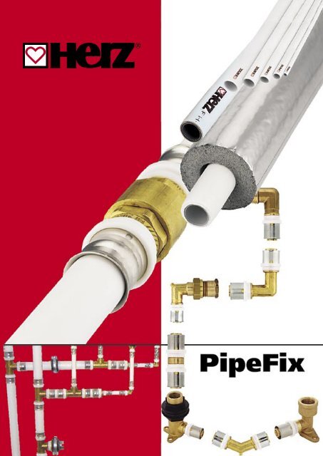
HERZ Plastic and aluminium composite pipe<br />
The HERZ composite pipe has been developed for<br />
multiple use and complex installation tasks. It is<br />
economical to process and is characterised by its<br />
high quality, safety and durability. It is also completely<br />
recyclable.<br />
This multi-layered pipe is manufactured with the<br />
most up-to-date production machines and is<br />
backed up by decades of experience and<br />
expertise. It consists of a basic pipe made from<br />
polyethylene, which is covered<br />
by a seam welded<br />
aluminium layer and covered<br />
by a further layer of polyethylene. This composite material<br />
combines the excellent characteristics of plastic with the<br />
proven advantages of aluminium. A consistent round pipe<br />
profile is achieved using this production process, which<br />
guarantees precise accuracy of fit for all connections.<br />
Only polyethylene (PE) is used for the HERZ composite<br />
pipe. PE is a polyolefin, consisting of the chemical elements<br />
of carbon and hydrogen, which is very similar to the<br />
molecular structure of wax, but the molecular chains are<br />
very much longer.<br />
The pipes are supplied in straight lengths or coils<br />
and are connected using HERZ press fittings or<br />
HERZ screw connections. HERZ pipe and HERZ<br />
connection fittings are tested for conformity to standards<br />
and accredited by externally recognised testing centres<br />
in many European countries. The system is registered as<br />
HERZ PipeFix.<br />
Polyethylene is a<br />
versatile plastic and<br />
can be recycled<br />
after being separated from<br />
the aluminium, for example,<br />
as an oil substitute in<br />
combustion plants. This<br />
aluminium layer gives the<br />
pipe rigidity, 100% watertightness<br />
and an oxygen<br />
barrier.<br />
H<br />
C<br />
H<br />
H<br />
C<br />
H<br />
HERZ pipes have good electrical conductivity due to the<br />
“continuous” aluminium layer. “Lateral” to the pipe shaft,<br />
the polyethylene layer works as an electrical insulator up to<br />
a voltage of around 35,000 V. It is not possible to earth the<br />
piping.<br />
HERZ plastic and aluminium composite pipes are used for<br />
under-floor heating, radiator heating and domestic water<br />
distribution. All HERZ pipes are printed as follows:<br />
> I < xxx m HERZ-HV pipe PE-xx/Al/PE-xx dimension x<br />
wall thickness country of production 95°C/10 bar tested<br />
date/time/equipment no./order no. /layer /operative no.<br />
High heat stabilised polymer outer pipe,<br />
white, UV stabilised<br />
Adhesion layer<br />
Uniform longitudinally butt-welded, absolutely round,<br />
solid aluminium pipe<br />
Adhesion layer<br />
High heat stabilised, PE-X or PE-RT inner pipe<br />
In addition to this there is the HERZ FH plastic and<br />
aluminium composite pipe with thinner aluminium layer<br />
for installation in floor or surface heating and cooling<br />
systems.<br />
HERZ plastic and aluminium composite pipe, PE-RT<br />
Pipe ID: PE-RT / AL / PE-HD<br />
Reference<br />
PE<br />
RT<br />
AL<br />
HD<br />
… Polyethylene<br />
... Raised temperature,<br />
Higher temperature<br />
... Aluminium<br />
... High density<br />
Supplied in coils or straight lengths in various thickness of<br />
aluminium depending on the pipe size (see table).<br />
Maximum operating temperature ... 95°C<br />
Maximum operating pressure<br />
... 10 bar<br />
Transient temperature and pressure (short-term) ... 110°C, 15 bar<br />
Inner surface roughness<br />
... 0.007mm<br />
Heat conductivity ... 0.5 W / m x °K<br />
Linear expansion coefficient<br />
... 0.024 mm/m°K<br />
Colour<br />
... white<br />
Oxygen diffusion<br />
...
HERZ Plastic and aluminium composite pipe<br />
HERZ<br />
order number<br />
Pipe Coil<br />
Outside Diameter<br />
(mm)<br />
Wall thickness<br />
(mm)<br />
Aluminium thickness<br />
(mm)<br />
Coils<br />
(m)<br />
Straight Lengths<br />
(m)<br />
Weight<br />
(kg / 100 m)<br />
Water capacity<br />
(L)<br />
3 C140 20 14 2 0.4 200 - 11.10 0.075<br />
3 C160 20 16 2 0.4 200 - 12.90 0.113<br />
3 C180 20 18 2 0.4 200 - 15.20 0.154<br />
3 C200 20 20 2 0.4 100 - 17.50 0.201<br />
3 C260 30 26 3 0.5 50 - 29.60 0.307<br />
3 C320 30 32 3 0.5 50 - 36.60 0.523<br />
3 C400 30 40 3.5 0.5 50 - 51.00 0.845<br />
Pipe lengths<br />
3 C160 34 16 2 0.4 - 5 12.90 0.113<br />
3 C200 34 20 2 0.4 - 5 17.50 0.154<br />
3 C260 35 26 3 0.5 - 5 29.60 0.307<br />
3 C320 35 32 3 0.5 - 5 36.60 0.523<br />
3 C400 36 40 3.5 0.5 - 5 51.00 0.845<br />
3 C500 45 50 4.0 0.6 - 5 87.00 1.385<br />
3 C630 45 63 4.5 0.8 - 5 131.50 2.229<br />
FH composite pipe<br />
3 C101 30 10 1.3 0.2 250 - 4.65 0.043<br />
3 D160 14 14 2 0.2 200 - 8.80 0.075<br />
3 D160 20 16 2 0.2 200 - 10.20 0.113<br />
3 D160 18 18 2 0.25 200 - 12.20 0.154<br />
HERZ<br />
order number<br />
Outside Diameter<br />
(mm)<br />
Wall thickness<br />
(mm)<br />
Aluminium thickness<br />
(mm)<br />
Coils<br />
(m)<br />
Protective pipe<br />
(m)<br />
Weight<br />
(kg / 100 m)<br />
Water capacity<br />
(L)<br />
3 C160 31 16 2 0.4 200 4 13.15 0.113<br />
3 C200 31 20 2 0.4 100 4 17.78 0.201<br />
3 C260 31 26 3 0.5 50 4 30.00 0.307<br />
3 C160 32 16 2 0.4 200 9 13.40 0.113<br />
Heating and sanitation pipes<br />
with thermal insulation<br />
Heating and domestic water pipes with varying thickness<br />
(4 mm and 9 mm) of insulation offer optimum protection<br />
against heat loss and also offer protection against<br />
mechanical damage.<br />
Pipe in pipe<br />
Heating or domestic water pipes drawn into a corrugated<br />
protective sleeve to protect pipes or to facilitate<br />
subsequent replacement during building refurbishment.<br />
HERZ<br />
order number<br />
Outside Diameter<br />
(mm)<br />
Wall thickness<br />
(mm)<br />
Aluminium thickness<br />
(mm)<br />
Coils<br />
(m)<br />
Protective pipe<br />
(m)<br />
Weight<br />
(kg / 100 m)<br />
Water capacity<br />
(L)<br />
3 C160 33 16 2 0.4 50 20/25 black 13.80 0.113<br />
3 C160 39 16 2 0.4 50 20/25 blue 13.80 0.113<br />
3 C200 33 20 2 0.4 50 25/30 black 18.30 0.201<br />
3 C200 39 20 2 0.4 50 25/30 blue 18.30 0.201<br />
2
HERZ Plastic and aluminium composite pipe<br />
HERZ plastic composite pipe, PE-Xc<br />
H<br />
Pipe ID: PE-Xc / AL / PE-Xc<br />
Reference<br />
PE … Polyethylene<br />
Xc ... X-linked<br />
AL ... Aluminium<br />
H<br />
C C<br />
H<br />
H<br />
H<br />
The composition of the spatial lattice structure is achieved<br />
using energy-rich betatron radiation. The accelerated<br />
ß particles provide the energy for the reaction of the<br />
molecular chain. Supplied in coils or straight lengths in<br />
various thickness of aluminium depending on the pipe<br />
size (see table).<br />
Maximum operating temperature ... 95°C<br />
Maximum operating pressure ... 10 bar<br />
Durability under these conditions ... 440,000 h (50 years)<br />
Transient temperature and pressure ... 110°C, 15 bar<br />
Inner surface roughness<br />
... 0.007 mm<br />
Heat conductivity<br />
... 0.39 W / m x°K<br />
Linear expansion coefficient ... 0.024 mm / m°K<br />
Colour<br />
... white<br />
Oxygen diffusion<br />
... < 0.005 mg/l d<br />
Minimum bending radius without tools ... 5d<br />
Minimum bending radius with tools ... 3d<br />
C<br />
H<br />
The molecule chains<br />
for high density<br />
polyethylenes are not<br />
directly connected to<br />
one another. The<br />
structure is held<br />
H<br />
together by two-way<br />
forces.<br />
C<br />
H<br />
H<br />
H<br />
C<br />
H<br />
H<br />
C<br />
H<br />
H<br />
C<br />
H<br />
H<br />
C<br />
H<br />
C<br />
H<br />
HERZ<br />
order number<br />
Outside Diameter<br />
(mm)<br />
Wall thickness<br />
(mm)<br />
Aluminium thickness<br />
(mm)<br />
Coils<br />
(m)<br />
Straight Lengths<br />
(m)<br />
Weight<br />
(kg/100m)<br />
Water capacity<br />
(L)<br />
3 A140 20 14 2 0.4 100 - 11.10 0.075<br />
3 A160 20 16 2 0.4 100 - 12.90 0.113<br />
3 A180 20 18 2 0.4 100 - 15.20 0.154<br />
3 A200 20 20 2 0.5 100 - 17.50 0.201<br />
3 A260 30 26 3 0.5 50 - 29.60 0.307<br />
3 A320 30 32 3 0.5 50 - 36.60 0.531<br />
3 A320 35 32 3 0.5 - 5 36.60 0.531<br />
3 A400 35 40 3.5 0.5 - 5 51.00 0.855<br />
3 A500 45 50 4 0.5 - 5 87.00 1.385<br />
3 A630 45 63 4.5 0.5 - 5 131.50 2.290<br />
Various methods are used for connecting chains to the<br />
network. Through the connection of existing transverse<br />
connections between the polyethylene molecular chains.<br />
These transverse connections reduce the movements of the<br />
molecular chains between themselves.<br />
H<br />
C<br />
H<br />
C<br />
H<br />
C<br />
PE<br />
X<br />
... Polyethylene<br />
... Cross linked<br />
H<br />
H<br />
H<br />
C<br />
... Methods of networking<br />
PE- Xa: Cross linked by organic peroxides<br />
(chemical connection) Engel procedure<br />
PE- Xb: Cross linked by silan followed by water treatment<br />
(chemical networking)<br />
PE- Xc: electronic connection using bombardment with<br />
electrons (physical networking)<br />
H<br />
C<br />
H<br />
H<br />
C<br />
H<br />
H<br />
C<br />
H<br />
3
HERZ Plastic and aluminium composite pipe<br />
Creep behaviour of HERZ pipe<br />
The creep behaviour indicates what maximum pipe<br />
wall stress (pipe inner pressure) is permissible under<br />
constant operating temperatures, in order to achieve<br />
a certain operating time. The hoop stress resistance,<br />
particularly due to the creep strength of the relatively thick<br />
aluminium layer, is proven in HERZ pipes.<br />
Inner creep pressure – behaviour according<br />
to DIN 16 892 for 16 x 2 mm pipe<br />
The creep behaviour of HERZ pipes is far above the<br />
temperatures relevant to the housing market for heating<br />
and domestic water installations. The HERZ pipe consists<br />
of various layers of materials, the individual contributions<br />
of which add to the creep strength of the whole pipe. An<br />
appropriate creep diagram can therefore be drawn for<br />
each individual pipe size.<br />
The creep behaviour is indicated by testing the pipe over<br />
10,000 hours, with a temperature 40°C higher than the<br />
maximum operating temperature. Afterwards, these results<br />
are extrapolated to 50 years with a safety factor of 1.5. In<br />
accordance with the standards, the pipes are dimensioned<br />
for 50-year durability. A decrease in the durability must be<br />
calculated where higher temperatures or pressures are<br />
used.<br />
Diagrams are available on request for other<br />
sizes or materials<br />
The linear expansion coefficient, independent of the pipe<br />
size, totals 0.024 mm/m°K.<br />
The length change between installation and operating<br />
temperature may be calculated using the following formula.<br />
24<br />
Thermal expansion<br />
∆l = a . l . ∆t<br />
∆l = length change<br />
a = Expansion coefficient (0.024 mm/m°K)<br />
l = installed pipe length (m)<br />
∆t = temperature difference between installation and<br />
operating temperature (K)<br />
22 10<br />
Length change ∆l [mm]<br />
20<br />
18<br />
16<br />
14<br />
12<br />
10<br />
8<br />
6<br />
4<br />
2<br />
0<br />
20 30 40 50 60 70 80 90<br />
Temperature difference ∆t [K]<br />
Pipe expansion is compensated by professional installation.<br />
9<br />
8<br />
7<br />
6<br />
5<br />
4<br />
3<br />
2<br />
1<br />
Pipe length l [m]<br />
4
HERZ Plastic and aluminium composite pipe<br />
With normally installed pipes or ‘pipe in pipe’<br />
installations, sufficient flexible sections must be left<br />
to compensate for the expansion. When installing buried<br />
Flexible section length BS [mm]<br />
BS = c . √ Da . ∆l<br />
2000<br />
1800<br />
1600<br />
1400<br />
1200<br />
1000<br />
800<br />
600<br />
400<br />
200<br />
0<br />
Expansion sections and fixing intervals<br />
or under screed (under-floor heating) pipes, the expansion<br />
is recorded as radial. The flexible section can calculated<br />
as follows:<br />
c = 33, (dimensionless material constants)<br />
Da = outer diameter of the pipe<br />
∆l = length change<br />
0 5 10 15 20 25 30 35 40 45 50<br />
Length expansion ∆l [mm]<br />
63<br />
50<br />
40<br />
32<br />
26<br />
20<br />
16<br />
14<br />
Pipe outer diameter Da [mm]<br />
Loose laid pipes do not require any supports, such as<br />
clips, clamps, etc. due to their stable shape. The support<br />
intervals can be found in the table below. Plastic or metal<br />
pipe clamps should have a soft lining, of rubber or another<br />
soft material, in order to avoid damage to the pipe and to<br />
reduce noise transmission.<br />
Dimension<br />
(mm)<br />
Support<br />
Interval B (m)<br />
Dimension<br />
(mm)<br />
Support<br />
Interval B (m)<br />
14 0.8 32 1.6<br />
16 0.8 40 1.7<br />
20 1 50 1.8<br />
26 1.2 63 2<br />
The arrangement of fixed points and sliding supports is very<br />
important when installing, so that sufficient flexible sections<br />
are available. Fittings (elbows , ‘T’s etc) are recommended<br />
for changes in direction, For pipe sizes DN 32 and above<br />
they must be utilised. The pipe expansion can be halved by<br />
around 50% by pre-stressing the pipes.<br />
Pipe expansion for directional changes,<br />
flexible section to be calculated using the<br />
diagram<br />
Inclusion of the pipe expansion in long pipes, including<br />
expansion through U-bends, flexible sections by<br />
calculation or from the diagram<br />
5
HERZ Plastic and aluminium composite pipe<br />
For risers it is advisable to set the fixed point in the middle<br />
of the run. The result is smaller intervals for the flexible<br />
sections.<br />
Fixed point at the end of the ascending pipe = flexible sections<br />
become increasingly larger<br />
Fixed point in the centre of the ascending pipe = flexible sections<br />
remain relatively short<br />
Protective pipes should be used when working through wall<br />
or ceilings. To avoid severe damage to the pipes, the pipes<br />
should not be bent around sharp angles. For rounding off,<br />
sufficiently large openings should be used.<br />
For pipes branching off into ducts, care should be taken<br />
that the flexible sections are maintained. If this is not<br />
possible, then the duct should be made sufficiently large<br />
to allow for the expansion. A protective pipe running<br />
through the duct is recommended.<br />
The pipe can be bent using a bending tool such as<br />
an inner or outer spring, or the usual bending tools<br />
or by hand. The minimum bending radii must always<br />
Bending radii<br />
be adhered to. For DN 32 pipes or larger, fittings must<br />
always be used.<br />
DN Radius with bending tool (mm) Radius without bending tool (mm)<br />
10 50 100<br />
14 70 140<br />
16 80 160<br />
18 90 180<br />
20 100 200<br />
26 130 260<br />
32 -63 HERZ PipeFix elbows HERZ PipeFix elbows<br />
For a working environment temperature less than +5°C<br />
there is an increased risk of the pipe snapping or kinking<br />
during bending. For bending pipes under +5°C the relevant<br />
part of the pipe must be warmed up.<br />
6
HERZ Plastic and aluminium composite pipe<br />
Pipe bends after a press fitting or clip must have a section<br />
of pipe 5 x DN between fitting and bend in order to avoid<br />
damage to the pipes.<br />
Where there are creases in the piping these sections must<br />
always be changed.<br />
5 x DN<br />
Durability<br />
Durability against chemicals, hard drinking water, etc.<br />
comes from the characteristics of polyethylene. The<br />
medium does not come into contact with the aluminium<br />
pipe. The advantages of polyethylene lie in the fact that<br />
it is odour and taste-neutral, it is very durable, has a high<br />
capacity as well as its validity for food use and is recyclable.<br />
Where installing in areas with high concentrations of<br />
chemical gases or moisture (stables, large kitchens, etc.)<br />
the metallic connection parts must be protected.<br />
The aluminium pipe gives it resistance against UV rays.<br />
The growth of algae requires UV rays and is therefore<br />
prevented. Short ray UV rays encourage plastics to age.<br />
The high density PE outer casing is sufficiently stable for<br />
surface installation in buildings, so that further protective<br />
measures are superfluous.<br />
Processing and operating temperatures<br />
The lowest operating temperature for PE is –20°C, and<br />
an installation temperature of –40°C is possible.<br />
The material used, PE, has a good resistance against<br />
glycol-based frost protection materials. Where it is used at<br />
less than 0°C, the use of anti-freeze is essential.<br />
The use of electrical heating tape to keep the piping free<br />
of frost is an option. For better heat distribution the heating<br />
tape can be fitted with adhesive foil. Heating tape must be<br />
technically tested and have the appropriate accreditation.<br />
Heating tape is only suitable for frost protection and not<br />
for additional heating. The advice of HERZ engineers is<br />
required for any other solutions.<br />
For temperatures lower than +5°C the pipes must not be<br />
subjected to unreasonably harsh external mechanical<br />
loads. The pipes are installed free of stress – without<br />
stress from bending, pulling or torsion. For tight bending<br />
radii under an installation temperature of 0°C there is an<br />
increased risk of the pipe snapping off. We recommend<br />
the use of bending aids and the corresponding pipe parts<br />
being warmed to a temperature of over +5°C. The press<br />
tool must also guarantee sufficient press strength at low<br />
temperatures. The details from the tool manufacturer must<br />
be noted here.<br />
Behaviour in fire<br />
During the manufacture of HERZ pipes only polyolefinbased<br />
plastics are used in addition to aluminium.<br />
During normal combustion the same fumes are given off<br />
as when a candle burns out. Unfavourable conditions<br />
(too little oxygen) may produce carbon monoxide or soot,<br />
which always occurs during the incomplete combustion of<br />
organic matter. Aluminium is incombustible under normal<br />
conditions. Oxidation products are non-toxic and are often<br />
even an element of natural soil composition. No halogens,<br />
acids or other toxic environmentally harmful materials are<br />
released during the combustion of HERZ pipes.<br />
Where ventilation zones are crossed, the standards<br />
Instances of usage<br />
HERZ pipes can be used in all heating and cooling<br />
systems as well as in domestic and service water<br />
installations. HERZ pipes are also most suitable for underfloor<br />
heating systems or to heat and cool areas in walls,<br />
corresponding to fire protection system shutting devices<br />
to prevent the spread of fire are to be used. These system<br />
shutting devices may be yielding partitions, fire protection<br />
pads or fire protection sleeves. These partitions shut<br />
down the area of the fire after the plastic pipes are burnt<br />
away. HERZ plastic pipes fall into fire category B2 (normal<br />
inflammable building materials) according to DIN 4102,<br />
Part 1.<br />
ceilings and floors.<br />
For special requirements such as lawn heating or concrete<br />
core cooling HERZ pipes can also be used. Where wall<br />
heating or cooling panels are used, HERZ pipes of size<br />
10 x 1.3 mm are used. Where diffusion-tight pipes are used<br />
(oxygen and steam diffusion) there is no need for system<br />
separation with heat exchangers.<br />
Oxygen diffusion causes bacteria in the water that leads to<br />
the accumulation of matter in pipes. This matter can form<br />
deposits in the pipe inner wall and lead to reduced flow. The<br />
pipe resistance is increased until there is no flow. This then<br />
requires very expensive chemical cleaning.<br />
7
HERZ Plastic and aluminium composite pipe<br />
Pipe friction loss diagram<br />
Flow velocity (m/s)<br />
Mass flow rate m (kg/h)<br />
Pressure loss (Pa/m)<br />
1 mbar = 100 Pa<br />
HERZ press fittings can be connected quickly and<br />
with absolute safety in conjunction with <strong>Herz</strong> multilayer<br />
pipes. <strong>Herz</strong>, with its decades of experience in<br />
pipe connections, produces radial press fittings of<br />
dezincification-resistant brass with stainless steel bushes,<br />
of recognised higher quality, based on its own in-house<br />
HERZ installation aids and HERZ fittings<br />
Galvanic separation via graduation<br />
patented developments. These are available in a large<br />
range of forms and sizes for the connection of plastic<br />
composite pipes for heating and cooling systems. Our<br />
experience is your security, with a 10-year guarantee for<br />
HERZ PipeFix systems.<br />
Stainless steel press sleeves<br />
Double O-ring<br />
Dezincification-resistant brass<br />
Plastic ring for centering press sleeves<br />
and for tool guidance<br />
8
HERZ Plastic and aluminium composite pipe<br />
Processing of HERZ pipes with HERZ fittings<br />
The pipe is cut perpendicular, with a suitable tool.<br />
The pipe is trimmed and calibrated with the special tool<br />
suitable for its diameter. The resulting shavings must be<br />
removed from the end of the pipe. If the calibrator is fixed<br />
in a drilling machine, the maximum revolutions of 10rpm<br />
must not be exceeded.<br />
Placing the fitting on the pipe.<br />
Check the correct pipe engagement through the vision ports<br />
on the press sleeve – the pipe must have fully engaged on the<br />
fitting and be visible in the ports.<br />
Complete pressure sealing using a press device or manual<br />
press pliers. The pipes must be free of stress. The press<br />
procedure is complete if the jaws have been closed<br />
completely.<br />
Press tools are precision tools and should be handled accordingly. HERZ PipeFix<br />
is pressed using the profile “TH”, so that the usual tools (hand press device, accupress<br />
device, etc.)can be used. Small “A” intervals to the wall or floor are possible.<br />
DN<br />
A<br />
(mm)<br />
DN<br />
A<br />
(mm)<br />
DN<br />
A<br />
(mm)<br />
10 25 20 30 40 40<br />
14 25 26 30 50 70<br />
16 25 32 40 63 70<br />
Checking the pressure sealing:<br />
On the side of the press sleeves you can see two<br />
parallel, ring-shaped pressed grooves with a bulge<br />
between them.<br />
Non-detachable connections such as press fittings can be buried after installation (See local or national legislation for<br />
confirmation). Press connections are prohibited from being buried in floors in the Fernwärme Wien (Vienna’s remote heating<br />
programme) area. To avoid corrosion to the fittings there must be galvanic separation from the concrete or masonry using<br />
moisture insulation. This insulation can, for example, be carried out using heat shrinking materials or corrosion protection<br />
tape. In each case, compatibility with the pipe material and fitting must be checked.<br />
9
HERZ Plastic and aluminium composite pipe<br />
It is imperative that the stated pipe diameter and pipe wall thickness are adhered to when processing.<br />
Connection resistances<br />
Pipe<br />
dim.<br />
Pipe<br />
bend<br />
Angles T-piece flow<br />
re-director,<br />
one-way<br />
(1 into 2)<br />
T-piece flow<br />
mixer<br />
(2 into 1)<br />
T-piece flow<br />
re-director<br />
two-way<br />
(1 into 2)<br />
T-piece flow<br />
collection<br />
(2 into 1)<br />
Passage<br />
piece<br />
wall angles<br />
Values in equivalent pipe lengths in m<br />
14 0.70 1.50 1.30 1.60 1.70 1.70 1.00 1.40<br />
16 0.60 1.40 1.20 1.50 1.60 1.60 0.90 1.30<br />
18 0.55 1.20 0.90 1.40 1.50 1.50 0.70 1.20<br />
20 0.50 1.10 0.60 1.30 1.40 1.40 0.50 1.10<br />
26 0.40 1.00 0.50 1.20 1.30 1.30 0.40<br />
32 0.30 0.80 0.30 1.00 1.10 1.10 0.30<br />
40 0.26 0.76 0.28 0.95 1.00 1.00 0.26<br />
50 0.22 0.72 0.26 0.90 0.95 0.95 0.22<br />
63 0.18 0.70 0.24 0.85 0.90 0.90 0.18<br />
To simplify the pipe network calculation the resistance<br />
values of the fittings are given in equivalent pipe<br />
lengths. These pipe lengths are to be found in the<br />
above table and are added to the length of the pipe<br />
network when calculating the pipe network.<br />
∆p g<br />
R<br />
I<br />
Z<br />
∆p v<br />
∆p g<br />
= R · I + Z + ∆p v<br />
Total pressure loss in the heating circuit<br />
Pressure loss per running m of pipe [Pa/m]<br />
Pipe length in m<br />
Sum of the individual resistances<br />
Pressure loss of the heating circuit thermostatic valves<br />
HERZ Angle with internal thread<br />
B<br />
A<br />
H<br />
L<br />
Order number A B L H<br />
P 7114 21 14 x 2 1/2 53 34<br />
P 7116 21 16 x 2 1/2 44 34<br />
P 7118 21 18 x 2 1/2 53 34<br />
P 7120 21 20 x 2 1/2 50 34<br />
P 7120 22 20 x 2 3/4 52 45<br />
P 7126 22 26 x 3 3/4 56 45<br />
P 7132 23 32 x 3 1 55 49<br />
P 7140 24 40 x 3,5 11⁄4 55 55<br />
P 7150 24 50 x 4 11⁄4 76 63<br />
P 7150 25 50 x 4 11⁄2 76 63<br />
P 7163 26 63 x 4,5 2 83 70<br />
10
HERZ Plastic and aluminium composite pipe<br />
HERZ Angle with external thread<br />
B<br />
L<br />
Order number A B L H<br />
P 7114 11 14 x 2 1/2 53 34<br />
P 7116 11 16 x 2 1/2 44 34<br />
P 7118 11 18 x 2 1/2 53 34<br />
P 7120 11 20 x 2 1/2 50 34<br />
P 7120 12 20 x 2 3/4 50 34<br />
P 7126 12 26 x 3 3/4 56 45<br />
P 7132 13 32 x 3 1 55 49<br />
P 7140 14 40 x 3.5 11⁄4 55 55<br />
P 7150 14 50 x 4 11⁄4 76 61<br />
P 7163 16 63 x 4.5 2 83 70<br />
HERZ Coupling, Reduced Coupling<br />
A<br />
B<br />
A<br />
H<br />
L<br />
Order number A B L<br />
P 7010 00 10 x 1.3 10 x 1.3 41<br />
P 7014 00 14 x 2 14 x 2 65<br />
P 7016 00 16 x 2 16 x 2 58<br />
P 7016 01 16 x 2 14 x 2 65<br />
P 7018 00 18 x 2 18 x 2 65<br />
P 7018 01 18 x 2 14 x 2 65<br />
P 7018 02 18 x 2 16 x 2 65<br />
P 7020 00 20 x 2 20 x 2 58<br />
P 7020 03 20 x 2 14 x 2 62<br />
P 7020 01 20 x 2 16 x 2 62<br />
P 7020 02 20 x 2 18 x 2 65<br />
P 7026 00 26 x 3 26 x 3 65<br />
P 7026 01 26 x 3 16 x 2 65<br />
P 7026 03 26 x 3 17 x 2 65<br />
P 7026 05 26 x 3 18 x 2 65<br />
P 7026 02 26 x 3 20 x 2 65<br />
P 7032 00 32 x 3 32 x 3 65<br />
P 7032 01 32 x 3 16 x 2 65<br />
P 7032 07 32 x 3 18 x 2 65<br />
P 7032 02 32 x 3 20 x 2 65<br />
P 7032 06 32 x 3 26 x 3 65<br />
P 7040 00 40 x 3.5 40 x 3.5 65<br />
P 7040 02 40 x 3.5 26 x 3 65<br />
P 7040 03 40 x 3.5 32 x 3 65<br />
P 7050 00 50 x 4 50 x 4 97<br />
P 7050 01 50 x 4 26 x 3 81<br />
P 7050 02 50 x 4 32 x 3 81<br />
P 7050 03 50 x 4 40 x 3.5 81<br />
P 7063 00 63 x 4.5 63 x 4.5 98<br />
P 7063 01 63 x 4.5 26 x 3 82<br />
P 7063 02 63 x 4.5 32 x 3 82<br />
P 7063 03 63 x 4.5 40 x 3.5 82<br />
P 7063 04 63 x 4.5 50 x 4 98<br />
11
HERZ Plastic and aluminium composite pipe<br />
HERZ End-stop<br />
A<br />
Order number A L<br />
P 7014 10 14 x 2 33<br />
P 7016 10 16 x 2 31<br />
P 7017 10 17 x 2 33<br />
P 7018 10 18 x 2 33<br />
P 7020 10 20 x 2 31<br />
P 7026 10 26 x 3 33<br />
P 7032 10 32 x 3 33<br />
P 7040 10 40 x 3,5 33<br />
P 7050 10 50 x 4 49<br />
P 7063 10 63 x 4,5 49<br />
L<br />
HERZ T-piece<br />
B<br />
A<br />
C<br />
H<br />
Order number A B C L H<br />
P 7214 00 14 x 2 14 x 2 14 x 2 83 42<br />
P 7214 01 14 x 2 16 x 2 14 x 2 83 42<br />
P 7216 00 16 x 2 16 x 2 16 x 2 77 39<br />
P 7216 01 16 x 2 14 x 2 16 x 2 83 42<br />
P 7216 05 16 x 2 18 x 2 16 x 2 88 44<br />
P 7216 03 16 x 2 20 x 2 16 x 2 83 42<br />
P 7217 00 17 x 2 17 x 2 17 x 2 107 54<br />
P 7218 00 18 x 2 18 x 2 18 x 2 83 42<br />
P 7218 01 18 x 2 14 x 2 18 x 2 88 44<br />
P 7218 02 18 x 2 16 x 2 18 x 2 88 44<br />
P 7220 00 20 x 2 20 x 2 20 x 2 83 42<br />
P 7210 00 20 x 2 10 x 1.3 20 x 2 88 33<br />
P 7220 10 20 x 2 14 x 2 20 x 2 88 44<br />
P 7220 02 20 x 2 18 x 2 20 x 2 88 44<br />
P 7220 06 20 x 2 26 x 3 20 x 2 102 51<br />
P 7220 01 20 x 2 16 x 2 20 x 2 83 42<br />
P 7220 03 20 x 2 16 x 2 16 x 2 83 42<br />
P 7220 08 20 x 2 20 x 2 16 x 2 83 42<br />
P 7226 00 26 x 3 26 x 3 26 x 3 102 51<br />
P 7226 17 26 x 3 32 x 3 26 x 3 106 53<br />
P 7226 03 26 x 3 16 x 2 26 x 3 97 49<br />
P 7226 04 26 x 3 18 x 2 26 x 3 102 51<br />
P 7226 05 26 x 3 20 x 2 26 x 3 97 49<br />
P 7232 00 32 x 3 32 x 3 32 x 3 106 53<br />
P 7232 10 32 x 3 40 x 3.5 32 x 3 106 53<br />
P 7232 01 32 x 3 16 x 2 32 x 3 106 53<br />
P 7232 03 32 x 3 18 x 2 32 x 3 106 53<br />
P 7232 04 32 x 3 20 x 2 32 x 3 106 53<br />
P 7232 07 32 x 3 26 x 3 32 x 3 106 53<br />
P 7240 00 40 x 3.5 40 x 3.5 40 x 3.5 110 55<br />
P 7240 12 40 x 3.5 50 x 4 40 x 3.5 120 76<br />
P 7240 02 40 x 3.5 26 x 3 40 x 3.5 110 55<br />
P 7240 03 40 x 3.5 32 x 3 40 x 3.5 110 55<br />
P 7250 00 50 x 4 50 x 4 50 x 4 152 76<br />
P 7250 03 50 x 4 26 x 3 50 x 4 152 62<br />
P 7250 01 50 x 4 32 x 3 50 x 4 152 62<br />
P 7250 02 50 x 4 40 x 3.5 50 x 4 152 61<br />
P 7263 00 63 x 4.5 63 x 4.5 63 x 4.5 166 83<br />
P 7263 01 63 x 4.5 32 x 3 63 x 4.5 166 67<br />
P 7263 02 63 x 4.5 40 x 3.5 63 x 4.5 153 70<br />
P 7263 03 63 x 4.5 50 x 4 63 x 4.5 166 83<br />
L<br />
12
HERZ Plastic and aluminium composite pipe<br />
HERZ T-piece, reduced<br />
B<br />
A<br />
C<br />
H<br />
Order number A B C L H<br />
P 7216 02 16 x 2 14 x 2 14 x 2 83 42<br />
P 7218 04 18 x 2 16 x 2 14 x 2 107 54<br />
P 7218 03 18 x 2 16 x 2 16 x 2 88 44<br />
P 7220 11 20 x 2 14 x 2 16 x 2 88 44<br />
P 7220 03 20 x 16 x 2 16 x 2 83 42<br />
P 7220 07 20 x 2 16 x 2 18 x 2 88 44<br />
P 7220 04 20 x 2 18 x 2 18 x 2 88 44<br />
P 7220 09 20 x 2 20 x 2 14 x 2 88 44<br />
P 7220 08 20 x 2 20 x 2 16 x 2 88 44<br />
P 7226 18 26 x 3 18 x 2 18 x 2 102 51<br />
P 7226 12 26 x 3 18 x 2 20 x 2 102 51<br />
P 7226 13 26 x 3 20 x 2 16 x 2 102 51<br />
P 7226 14 26 x 3 20 x 2 20 x 2 102 51<br />
P 7226 19 26 x 3 20 x 2.5 16 x 2 102 51<br />
P 7226 16 26 x 3 26 x 3 16 x 2 112 56<br />
P 7226 15 26 x 3 26 x 3 20 x 2 112 56<br />
P 7232 11 32 x 3 20 x 2 26 x 3 106 53<br />
P 7232 09 32 x 3 26 x 3 26 x 3 106 53<br />
P 7232 15 32 x 3 32 x 3 20 x 2 106 53<br />
P 7232 14 32 x 3 32 x 3 26 x 3 106 53<br />
P 7240 06 40 x 3.5 26 x 3 32 x 3 110 55<br />
P 7240 04 40 x 3.5 32 x 3 32 x 3 110 50<br />
P 7240 07 40 x 3.5 40 x 3.5 26 x 3 110 55<br />
P 7240 08 40 x 3.5 40 x 3.5 32 x 3 110 55<br />
P 7250 06 50 x 4 32 x 3 40 x 3.5 152 62<br />
P 7250 05 50 x 4 40 x 3.5 40 x 3.5 152 62<br />
P 7250 07 50 x 4 50 x 4 32 x 3 152 76<br />
P 7250 08 50 x 4 50 x 4 40 x 3.5 152 76<br />
P 7263 04 63 x 4.5 40 x 3.5 50 x 4 166 67<br />
P 7263 05 63 x 4.5 50 x 4 50 x 4 166 83<br />
P 7263 06 63 x 4.5 63 x 4.5 40 x 3.5 150 83<br />
P 7263 07 63 x 4.5 63 x 4.5 50 x 4 166 83<br />
L<br />
HERZ T-piece with external thread<br />
B<br />
A<br />
C<br />
H<br />
Order number A B C L H<br />
P 7216 51 16 x 2 1/2 16 x 2 90 34<br />
P 7218 51 18 x 2 1/2 18 x 2 98 34<br />
P 7220 51 20 x 2 1/2 20 x 2 91 34<br />
P 7226 51 26 x 3 1/2 26 x 3 112 38<br />
P 7220 52 20 x 2 3/4 20 x 2 98 34<br />
P 7226 52 26 x 3 3/4 26 x 3 112 38<br />
P 7232 51 32 x 3 3/4 32 x 3 110 47<br />
P 7226 53 26 x 3 1 26 x 3 112 43<br />
P 7232 52 32 x 3 1 32 x 3 110 47<br />
P 7240 52 40 x 3.5 1 40 x 3.5 110 55<br />
P 7240 53 40 x 3.5 11⁄4 40 x 3.5 110 55<br />
P 7250 53 50 x 4 11⁄4 50 x 4 152 61<br />
P 7250 54 50 x 4 11⁄2 50 x 4 152 61<br />
P 7263 54 63 x 4.5 11⁄2 63 x 4.5 166 68<br />
P 7263 55 63 x 4.5 2 63 x 4.5 166 70<br />
L<br />
13
HERZ Plastic and aluminium composite pipe<br />
HERZ T-piece with internal thread<br />
B<br />
A<br />
C<br />
H<br />
Order number A B C L H<br />
P 7216 41 16 x 2 1/2 16 x 2 90 34<br />
P 7218 41 18 x 2 1/2 18 x 2 98 34<br />
P 7220 41 20 x 2 1/2 20 x 2 91 34<br />
P 7226 42 26 x 3 1/2 20 x 2 112 38<br />
P 7226 41 26 x 3 1/2 26 x 3 112 37<br />
P 7232 43 32 x 3 1/2 32 x 3 110 47<br />
P 7220 42 20 x 2 3/4 20 x 2 112 43<br />
P 7226 44 26 x 3 3/4 26 x 3 112 43<br />
P 7232 41 32 x 3 3/4 32 x 3 110 47<br />
P 7232 42 32 x 3 1 32 x 3 110 47<br />
P 7240 41 40 x 3.5 1 40 x 3.5 110 55<br />
P 7232 44 32 x 3 11⁄4 32 x 3 125 55<br />
P 7240 42 40 x 3.5 11⁄4 40 x 3.5 110 55<br />
P 7250 42 50 x 4 11⁄4 50 x 4 152 63<br />
P 7250 43 50 x 4 11⁄2 50 x 4 152 63<br />
P 7263 43 63 x 4.5 11⁄2 63 x 4.5 166 68<br />
P 7263 44 63 x 4.5 2 63 x 4.5 166 70<br />
L<br />
HERZ 90° angle<br />
A<br />
L<br />
B<br />
H<br />
Order number A B L H<br />
P 7114 00 14 x 2 14 x 2 42 42<br />
P 7116 00 16 x 2 16 x 2 39 39<br />
P 7118 00 18 x 2 18 x 2 42 42<br />
P 7120 00 20 x 2 20 x 2 42 42<br />
P 7110 00 20 x 2 10 x 1.3 42 33<br />
P 7126 00 26 x 3 26 x 3 49 49<br />
P 7132 00 32 x 3 32 x 3 53 53<br />
P 7140 00 40 x 3.5 40 x 3.5 55 55<br />
P 7150 00 50 x 4 50 x 4 76 76<br />
P 7163 00 63 x 4.5 63 x 4.5 83 83<br />
Compression connections are manufactured using<br />
HERZ plastic pipe connectors. The HERZ adapter and<br />
screw connections are also used for pipe connections.<br />
The plastic pipe connection represents a completely safe<br />
connection between the pipe and valve. This connection<br />
can be detached at any time as required. Compression<br />
connections must not be used for buried systems. Perfect<br />
liquid tightness is only achieved if the installation is carried<br />
out in accordance with the HERZ installation instructions.<br />
It is imperative that the stated pipe diameter and pipe wall<br />
thickness are adhered to when installing compression<br />
connections.<br />
Compression Connections<br />
1) Non-detachable connections:<br />
- Press fittings for heating systems may be buried in the<br />
wall or the floor.<br />
- Press fittings for domestic water systems may be buried<br />
in the wall but not in the floor.<br />
- Press fittings for remote heating systems for Fernwärme<br />
Wien may not be buried in the wall or floor.<br />
2) Detachable connections must always remain accessible<br />
in order for liquid tightness to be checked.<br />
14
HERZ Plastic and aluminium composite pipe<br />
The pipe is cut perpendicular to the pipe axis<br />
and calibrated. The plastic screw connections are<br />
installed and tightened by hand.<br />
The grommets are fitted with an insulation plate for<br />
electrical separation from the aluminium.<br />
Installation of HERZ plastic screw connections<br />
A suitable spanner is used according to the design of the connection.<br />
24 27 36<br />
11⁄4 (450°) 1 (360°) 1 (360°)<br />
Plastic screw connection M 22 x 1,5 Plastic screw connection G 3/4 Plastic screw connection G1<br />
1 6066 xx and 1 6067 xx 1 6098 xx 1 6198 xx<br />
Order numbers from the HERZ catalogue, part 3.<br />
HERZ clamp set, 1 6092 xx for plastic pipe connections, suitable for the connection of PE-X-, PB- and aluminium composite<br />
pipes to radiator fittings in the “D” dimension range (with DIN thread lengths).<br />
Consisting of clamp nut, and spigot piece.<br />
Cut off the pipe at a right angle and trim. Slide on<br />
the clamp nut, push in the spigot piece.<br />
Place the pipe into the clamping ring.<br />
Connect to the fitting with<br />
the clamp nut.<br />
Tighten with a suitable tool.<br />
24<br />
1 6092 01 HERZ compression set for plastic pipe connections, 16 x 2.0 mm<br />
1 6092 02 HERZ compression set for plastic pipe connections, 14 x 2.0 mm<br />
For easier tightening, connection pieces (spigot piece and clamp nut) can be lubricated. Silicone or Teflon-based lubricants<br />
are perwithted. Lubricants containing mineral oil or hydrocarbon must not be used as they damage sealing elements.<br />
For detachable pipe connections, it can also be combined with HERZ screw fittings made of nickel-plated brass.<br />
Order numbers from the HERZ catalogue, part 3.<br />
15
HERZ Plastic and aluminium composite pipe<br />
Nap plate with or without bottom insulating layer<br />
Application of HERZ pipes and connections<br />
HERZ nap plate for laying pipes for under-floor heating, for pipes of 14 to 17 mm<br />
diameter.<br />
HERZ nap plates are particularly flexible and have good pipe holding strength. The<br />
advantages are: one-man laying, little cutting, simple correction of pipe laying, moisture<br />
protection according to DIN 18560. Particularly suitable for cement, floating screed and<br />
environmentally-friendly material suitable for material recycling.<br />
Pipe separation of 50 mm and multiples thereof (100, 150, 200, etc.) Plate size, 1400 x 800 mm, and the plates are laid with<br />
an overlap of 50 mm, effective area 1.12 m².<br />
Supplied in two designs:<br />
3 F030 01 nap plate with tread noise insulation, 30-2, made of hard polystyrene foam (EPS)<br />
3 F030 02 nap plate with heat insulation, 11 mm, made of hard polystyrene foam (EPS)<br />
3 F030 03 nap plate for individual heat insulation design<br />
The diagonal retainer, 3 F030 04, is also available for the diagonal laying of pipes.<br />
Multi-clamping system plate made from hard polystyrene foam, for increased loads, with pre-prepared laying grids for ease<br />
of laying under-floor heating without additional pipe fixing accessories. Can also be used for dry screed.<br />
Even and effective surface heating using comprehensive pure aluminium foil. Turns and re-directions are also made with<br />
aluminium re-direction plates. Pipe laying interval, 125 mm or multiples thereof. The plate can subsequently be treated with a<br />
knife or a hot cropping device. Plate size, 1,000 x 500 mm for pipe diameters of 16 or 17 mm. Heat conductivity, 0.035 W/mK<br />
according to ÖNORM B6015.<br />
16
HERZ Plastic and aluminium composite pipe<br />
Supplied in two designs with different insulation thickness:<br />
3 F020 01 multi-clamping plate, insulation thickness 30 mm<br />
3 F020 02 multi-clamping plate, insulation thickness 50 mm<br />
3 F020 03 re-direction plate, insulation thickness 30 mm<br />
3 F020 04 re-direction plate, insulation thickness 50 mm<br />
3 F020 05 plate without laying grids, insulation thickness 30 mm<br />
3 F020 06 plate without laying grids, insulation thickness 50 mm<br />
The multi-clamp system plates are most suitable for wall heating. To protect against aggressive screed or wall plaster, the<br />
system has to be covered using PE foil.<br />
When using for floor heating, a load distribution layer, e.g. with 2 x 10 mm Fermacell plates or chip-board panels, is required,<br />
which can be laid over with the multi-clamping plates.<br />
System rolls or system plates for floor heating, made of alu-metallised highly tear-proof woven film, insulation with tread<br />
insulation polystyrene and grids at intervals of 50 mm and with single-sided self-sticking overlaps of 40 mm. Simple laying<br />
by rolling out the system rolls or unfolding the folding plates. Pipe fixing with tacking needles. The reinforced film prevents<br />
tearing by the tacking needles. The pipe laying distance is selected individually with the help of the printed grid.<br />
Supplied in two designs with three different insulation thicknesses:<br />
3 F040 01 system roll, 1,000 x 10,000 mm, tread noise insulation, 15-2 mm<br />
3 F040 02 system roll, 1,000 x 10,000 mm, tread noise insulation, 22/20 mm<br />
3 F040 03 system roll, 1,000 x 10,000 mm, tread noise insulation, 32/30 mm<br />
3 F040 04 system plate, 1,000 x 2,000 mm, tread noise insulation, 15-2 mm<br />
3 F040 05 system plate, 1,000 x 2,000 mm, tread noise insulation, 22/20 mm<br />
3 F040 06 system plate, 1,000 x 2,000 mm, tread noise insulation, 32/30 mm<br />
Tacking needles and tacking device from the HERZ accessories catalogue, Part 3<br />
Notched rails made of plastic U-profile for fixing plastic pipes, diameter 16 and 17 mm for wall or under-floor heating. The<br />
notched rails are fixed to a heat insulator using double-sided sticking tape or tacking needles. The pipes are fixed at intervals<br />
of 50 mm or a multiple thereof, using formed pipe holder clips. The target break line every 100 mm serves to cross-cut the<br />
notched rails, or is cut off as required using a saw.<br />
Example version:<br />
Pipe laying for floor heating<br />
Floor heating – edge area<br />
3 F110 01 notched rails, length 2.1 m<br />
3 F110 02 notched rails, length 3.9 m<br />
17
HERZ Plastic and aluminium composite pipe<br />
All accessories for under-floor heating or cooling, such<br />
as screed test points, screed additives, sticking tape,<br />
edge insulation strips, expansion joint profiles, covering<br />
foil, angle pipe clasps, plate dowels, pipe holder dowels,<br />
hot cropping device, etc., are detailed in the HERZ<br />
brochure.<br />
Quick selection / summary of HERZ pipes, dimension 16 x 2.0 mm. 10K temperature difference<br />
Heat load for surface heating W/m 2 40 45 50 55 60 65 70 75 80 85 90 95 100 105 110 115 120 125 130<br />
Surface temperature of surface heating at a room temperature of 20°C 24.3 24.7 25.0 25.2 25.7 26.1 26.5 26.9 27.3 27.8 28.2 28.6 29.0 29.4 29.8 30.2 30.6 31.0 31.4<br />
Surface temperature of surface heating at a room temperature of 24°C 28.3 28.7 29.0 29.2 29.7 30.1 30.5 30.9 31.3 31.8 32.2 32.6 33.0 33.4 33.8 34.2 34.6 35.0 35.4<br />
Flow temperature 40 °C<br />
Flow temperature 45 °C<br />
Flow temperature 50 °C<br />
Flow temperature 55 °C<br />
Room temperature 20 °C<br />
Room<br />
temperature<br />
24 °C<br />
Room temperature 20 °C<br />
Room<br />
temperature<br />
24 °C<br />
Room temperature 20 °C<br />
Room<br />
temperature<br />
24 °C<br />
Room temperature 20 °C<br />
Room<br />
temperature<br />
24 °C<br />
Rλ.B=0,02<br />
Ceramic tiles<br />
VA in mm 250 200 150 100 70<br />
(m³K)/W Amax in m 2 36.7 30.3 22.1 14.3 8.9<br />
Rλ.B=0,05<br />
Wood / parquet<br />
VA in mm 200 150 100 70<br />
(m³K)/W Amax in m 2 30.2 22.4 15.5 9.75<br />
Rλ.B=0,10<br />
VA in mm 200 150 100 70<br />
Carpet<br />
(m³K)/W Amax in m 2 28.3 18.9 12.4 9.8<br />
Rλ.B=0,15 Deep-pile VA in mm 200 150 100<br />
(m³K)/W carpet Amax in m 2 25 19.7 13.5<br />
Rλ.B=0,02<br />
Ceramic tiles<br />
VA in mm 200 150 100 70<br />
(m³K)/W Amax in m 2 28.3 20.8 14.3 8.5<br />
Rλ.B=0,02<br />
Ceramic tiles<br />
VA in mm 250 200 150 100 70<br />
(m³K)/W Amax in m 2 38.1 28.8 20.3 14.5 9<br />
Rλ.B=0,05<br />
Wood / parquet<br />
VA in mm 200 150 100 70<br />
(m³K)/W Amax in m 2 30 20.6 14.4 8.7<br />
Rλ.B=0,10<br />
VA in mm 250 200 150 100 70<br />
Carpet<br />
(m³K)/W Amax in m 2 36.5 26.4 17.6 12.6 8.8<br />
R .B=0,15 Deep-pile VA in mm 250 200 150 100<br />
(m³K)/W carpet Amax in m 2 36 28.3 18.5 11.7<br />
Rλ.B=0,02<br />
Ceramic tiles<br />
VA in mm 200 150 100 70<br />
(m³K)/W Amax in m 2 31.2 20.5 14.5 9.5<br />
Rλ.B=0,02<br />
Ceramic tiles<br />
VA in mm 250 200 150 100<br />
(m³K)/W Amax in m 2 39.3 32.2 22 11.3<br />
Rλ.B=0,05<br />
Wood / parquet<br />
VA in mm 200 150 100 70<br />
(m³K)/W Amax in m 2 31.3 21.9 12.1 8.5<br />
Rλ.B=0,10<br />
VA in mm 250 200 150 100 70<br />
Carpet<br />
(m³K)/W Amax in m 2 40 34.5 24.8 15.4 8.4<br />
Rλ.B=0,15 Deep-pile VA in mm 250 200 150 100 70<br />
(m³K)/W carpet Amax in m 2 40 33.4 23.9 23 8.5<br />
Rλ.B=0,02<br />
Ceramic tiles<br />
VA in mm 200 150 100 70<br />
(m³K)/W Amax in m 2 34.5 24.5 16.2 9.7<br />
Rλ.B=0,02<br />
Ceramic tiles<br />
VA in mm 250 200 150 100<br />
(m³K)/W Amax in m 2 38 29.5 21.6 18<br />
Rλ.B=0,05<br />
Wood / parquet<br />
VA in mm 200 150 100<br />
(m³K)/W Amax in m 2 30.5 21.5 15.5<br />
Rλ.B=0,10<br />
VA in mm 250 200 150 100 70<br />
Carpet<br />
(m³K)/W Amax in m 2 39.4 32.3 23 15.5 8.5<br />
Rλ.B=0,15 Deep-pile VA in mm 250 200 150 100 70<br />
(m³K)/W carpet Amax in m 2 40 32.5 22.5 14 7.9<br />
Rλ.B=0,02<br />
Ceramic tiles<br />
VA in mm 200 150 100 70<br />
(m³K)/W Amax in m 2 32.5 23.7 17.3 15.4<br />
18
HERZ Plastic and aluminium composite pipe<br />
HERZ pipe and fittings in domestic water installations<br />
Example: Installation in partition walls in domestic areas with HERZ pipes<br />
HERZ pipe and fittings in radiator connection<br />
Example: Connection of HERZ under-floor/surface distributor HERZ SwitchFix 1 3030 01<br />
HERZ pipe and fittings in surface heating and cooling<br />
Connection of wall heating Renovation of apartments Installation of cooling ceiling<br />
19
HERZ Plastic and aluminium composite pipe<br />
For heating and cooling rooms in buildings, with attention to<br />
low energy costs, healthier air circulation without annoying<br />
operating noise with “hidden” comfort. Fermacell gypsumfibre<br />
plates, 15 mm, with ex-factory incorporated 10 x 1.3<br />
<strong>Herz</strong> composite pipe with 75 mm interval from the pipe<br />
HERZ air-conditioning system<br />
centre, in four different plate sizes for fast and clean laying<br />
in dry build in walls, floors or ceilings. Performance values<br />
for cold and hot water operation tested in accordance with<br />
EN 14037 at the accredited heating, ventilation and airconditioning<br />
testing centre in Stuttgart.<br />
3 F122 00 3 F120 75 3 F120 76 3 F120 77 3 F120 78<br />
The aluminium composite pipes are clamped at the factory<br />
in the ready-milled grooves of the gypsum-fibre plate. The<br />
panels are suitable for direct installation on a substructure on<br />
the wall, ceiling or floor. Panels are available in dimensions<br />
2,000 x 625, 2,000 x 310 und 1,000 x 625. The smooth plate<br />
side is the side that is seen and this installed facing out to the<br />
room and after the drill holes are puttied it can be painted,<br />
carpeted, tiled or covered with thin plaster.<br />
Panel heating plates made of 15 mm thick gypsumfibre<br />
plate, with integrated aluminium composite pipe,<br />
10.0 x 1.3 mm, oxygen-resistant according to DIN 4726,<br />
suitable for operating temperatures up to a maximum of<br />
45°C. The panel heating plates have to be fixed on a dry<br />
sub-construction, suitable for interiors and with a 31.2 cm<br />
interval. The press couplings and the panel heating plates,<br />
mounted in series, are connected directly to the distributor<br />
by means of coupling adapters. Before installation of the<br />
plates on the sub-structure, the pipe ends for connection<br />
to the supply circulation are released from the plate and<br />
directed into the room. Up to three whole plates are<br />
connected together and are connected to the distributors as<br />
a heating circuit. The panel heating plates (serial connection<br />
up to approximately 55 m pipes) is connected directly to the<br />
distributor outflow or a return temperature liwither.<br />
Wood or metal construction<br />
between insulation<br />
20
HERZ Plastic and aluminium composite pipe<br />
The heating plates can also be used<br />
for floor heating. A dry base of 2 x 10<br />
Fermacell plates is installed and the<br />
heating plates are then stuck and screwed<br />
to this dry base. The top covering is laid<br />
directly on the heating plates and may<br />
312,5 312,5<br />
be plastic, carpet, tiles or wood. The floor<br />
625<br />
covering must be suitable for the floor<br />
heating. The single or net load is to be<br />
adhered to in accordance with DIN 1055-3 (traffic load for ceilings).<br />
Construction<br />
Granules<br />
Floor construction with<br />
2 x 10 mm Fermacell plates<br />
For suspended ceilings the usual commercially available systems are used. To fix these constructions on solid floors,<br />
technically approved dowels must be used, which are suitable for this application and load. The profile of the suspension<br />
must be measured so that the static safety of the ceiling to be suspended from it is guaranteed. The intervals on the subconstruction<br />
for installing the heating plates is to be selected for the heating plate in accordance with the drilling plan.<br />
The construction must be measured so that the approved deflection of 1/500 of the support range is not exceeded.<br />
Where heating plates are used for ceiling heating, an insulation layer made of rock wool or polystyrene with a thickness<br />
of at least 100 mm is recommended. The weight of the insulation must be taken into account for calculating the ceiling<br />
construction.<br />
The heating plates are stuck fast together. The<br />
glue is applied from the cartridge. The surplus<br />
glue is scraped away after drying out (around<br />
24 hours) with a putty knife or wood chisel.<br />
The glue is frost-proof but requires moisture<br />
from the air to set. Plate customisations must,<br />
where possible, be laid with the cut edge in<br />
the direction of the expansion joint.<br />
312,5 312,5<br />
625<br />
Joint glue<br />
Lining up of the wall heating plates and<br />
empty plates as they only in danger of<br />
breaking at the edge. Processing of the<br />
gypsum-fibre plates > + 5 °C.<br />
Fixing of the gypsum-fibre plates with quick<br />
build screws.<br />
Screw length = plate thickness x 2 for metal<br />
frame constructions (30 mm)<br />
Screw length = plate thickness x 3 for<br />
wooden frame constructions (45 mm)<br />
The screws are sunk in around 2 mm and<br />
puttied in using the joint spatula.<br />
Customised plates under a width of 5 cm<br />
should be avoided for fixing because of the<br />
risk of fracture.<br />
Quick-build screws<br />
Joint spatula<br />
21
HERZ Plastic and aluminium composite pipe<br />
Heating table<br />
<strong>Herz</strong><br />
panel<br />
VL<br />
(°C)<br />
45<br />
40<br />
35<br />
30<br />
45<br />
40<br />
35<br />
30<br />
45<br />
40<br />
35<br />
30<br />
45<br />
40<br />
35<br />
30<br />
45<br />
40<br />
35<br />
30<br />
45<br />
40<br />
35<br />
30<br />
3 F120 75 3 F120 76 3 F120 77 3 F120 78<br />
WH 75 116-200<br />
3 F120 75<br />
WH 75 116-100<br />
3 F120 76<br />
WH 75 58-200<br />
3 F120 77 <strong>Herz</strong><br />
panel<br />
WH 75 58-100<br />
3 F120 78<br />
RT<br />
RL (°C) RL (°C) RL (°C) RT<br />
(°C) 25 30 35 40 45 25 30 35 40 45 25 30 35 40 45 (°C)<br />
122 144 165 182 78 92 105 116 61 72 82 91<br />
107 128 145 68 81 92 53 64 72<br />
15 15<br />
92 109 58 70 46 55<br />
76 48 38<br />
101 122 142 160 64 78 91 102 50 91 71 80<br />
86 106 123 55 67 79 43 53 62<br />
18 18<br />
71 88 45 56 35 44<br />
55 35 28<br />
87 108 128 145 55 69 81 92 43 54 64 72<br />
72 92 109 46 58 70 36 46 55<br />
20 20<br />
57 76 37 48 29 38<br />
42 27 21<br />
73 93 113 131 46 60 72 83 36 47 57 65<br />
59 78 95 37 50 61 29 39 48<br />
22 22<br />
44 62 28 40 22 31<br />
30 19 15<br />
59 80 99 116 38 51 63 74 30 40 49 58<br />
45 64 83 29 41 23 32 41<br />
24 24<br />
32 49 20 31 16 24<br />
18 11 9<br />
46 66 85 102 29 42 54 65 23 33 42 51<br />
33 51 69 21 32 44 16 25 34<br />
26 26<br />
19 36 12 23 10 18<br />
7 4 3<br />
45 33 53 71 88 21 33 45 56 17 26 36 44<br />
45<br />
40<br />
35<br />
28 21 38 55 13 24 35 10 19 28<br />
28<br />
8 24 5 15 4 12<br />
Performance values in watts, tested in accordance with EN 14037.<br />
VL<br />
(°C)<br />
45<br />
40<br />
35<br />
30<br />
45<br />
40<br />
35<br />
30<br />
45<br />
40<br />
35<br />
30<br />
45<br />
40<br />
35<br />
30<br />
45<br />
40<br />
35<br />
30<br />
45<br />
40<br />
35<br />
30<br />
40<br />
35<br />
22
HERZ Plastic and aluminium composite pipe<br />
Cooling table 3 F120 75<br />
3 F120 77 3 F120 78<br />
<strong>Herz</strong> panel P / 3 F120 75 P / 3 F120 77 - 3 F120 78<br />
RL<br />
RT<br />
VL<br />
16 17 18 19 20 21 16 17 18 19 20 21<br />
19 22 24 21 18 12 11 9,2<br />
19 23 31 27 24 15 14 12<br />
19 24 37 34 31 18 17 15<br />
19 25 43 40 37 22 20 18<br />
19 26 50 46 43 25 23 22<br />
19 27 56 53 50 28 27 25<br />
19 28 63 60 56 32 30 28<br />
19 29 70 66 63 35 33 32<br />
20 22 21 18 15 13 11 9 8 6<br />
20 23 27 24 21 18 14 12 11 9<br />
20 24 34 31 27 24 17 15 14 12<br />
20 25 40 37 34 31 20 18 17 15<br />
20 26 46 43 40 37 23 22 20 18<br />
20 27 53 50 46 43 27 25 23 22<br />
20 28 60 56 53 50 30 28 27 25<br />
20 29 66 63 60 56 33 32 30 28<br />
21 22 18 15 13 10 7 9 8 6 5 4<br />
21 23 24 21 18 15 13 12 11 9 8 6<br />
21 24 31 27 24 21 18 15 14 12 11 9<br />
21 25 37 34 31 27 24 18 17 15 14 12<br />
21 26 43 40 37 34 31 22 20 18 17 15<br />
21 27 50 46 43 40 37 25 23 22 20 18<br />
21 28 56 53 50 46 43 28 27 25 23 22<br />
21 29 63 60 56 53 50 32 30 28 27 25<br />
22 22 15 13 10 7 5 2 8 6 5 4 2 1<br />
22 23 21 18 15 13 10 7 11 9 8 6 5 4<br />
22 24 27 24 21 18 15 13 14 12 11 9 8 6<br />
22 25 34 31 27 24 21 18 17 15 14 12 11 9<br />
22 26 40 37 34 31 27 24 20 18 17 15 14 12<br />
22 27 46 43 40 37 34 31 23 22 20 18 17 15<br />
22 28 53 50 46 43 40 37 27 25 23 22 20 18<br />
22 29 60 56 53 50 46 43 30 28 27 25 23 22<br />
23 22 13 10 7 5 2 0 6 5 4 2 1 0<br />
23 23 18 15 13 10 7 5 9 8 6 5 4 2<br />
23 24 24 21 18 15 13 10 12 11 9 8 6 5<br />
23 25 31 27 24 21 18 15 15 14 12 11 9 8<br />
23 26 37 34 31 27 24 21 18 17 15 14 12 11<br />
23 27 43 40 37 34 31 27 22 20 18 17 15 14<br />
23 28 50 46 43 40 37 34 25 23 22 20 18 17<br />
23 29 56 53 50 46 43 40 28 27 25 23 22 20<br />
Performance values for cooling per panel in watts, tested in accordance with EN 14037.<br />
VL<br />
23
HERZ Plastic and aluminium composite pipe<br />
1 1 2414 02 multi-function valve, red<br />
2 1 2415 02 multi-function valve, blue<br />
3 1 7760 5x thermostat – cooling valve<br />
4 1 934x 00 thermostat with remote sensor<br />
5 1 6837 91 manual control valve<br />
4<br />
1 3 F120 75 wall-heating panel<br />
2 1 8532 xx distributors<br />
3 1 4217 xx circuit control valve<br />
4 1 4007 xx differential pressure control<br />
5 1 7723 xx area valve<br />
6 1 7710 00 thermomotor<br />
7 1 7217 xx area valve<br />
8 1 7794 23 Room temperature control<br />
1<br />
2<br />
5<br />
3<br />
Example: Mechanical control of a cooling circuit<br />
Example: Connection for heating and cooling<br />
Connection to HERZ distributor<br />
HERZ pipes can be connected to all distributors for drinking<br />
water, radiator connection and surface heating and cooling<br />
from the HERZ catalogue, using HERZ fittings.<br />
HERZ compact distributors, 1 8441 xx are supplied as pairs<br />
with 3 to 12 outlets with distributor holders, vent valve and<br />
end caps.<br />
HERZ compact distributors represent a simple system for the<br />
single connection of radiators. They consist of nickel-coated<br />
cast distributor components that can be coupled. They are<br />
produced as single components. Connection to one another<br />
utilises a protected O-ring seal, which remains water-tight<br />
and is reliable over time. The distributor assembled at the<br />
top is fitted with the ventilation valve.<br />
The distribution outlets are supplied with M 22 x 1.5 external<br />
threads. The connection of the distributor outlets to the<br />
HERZ pipes is achieved using connectors.<br />
1 7637 25<br />
1 8437 53<br />
1 8477 43<br />
1 8437 43<br />
1 8438 53<br />
End caps<br />
8445<br />
1 8438 43<br />
Shut-off valve DN 20<br />
8448<br />
Double caps<br />
G 3/4<br />
6098<br />
1 7723 22<br />
6274<br />
Clamping set G 3/4<br />
8447<br />
Crossover sleeve G 3/4<br />
6284<br />
6286 6066 1056<br />
Clamping sets M 22 x 1,5<br />
Locking cap<br />
HERZ compact distributors, 1 8541 xx are supplied as pairs<br />
of distributors with 3 to 12 outlets with distributor holders,<br />
vent valve and end caps.<br />
HERZ compact distributors represent a simple system for the<br />
single connection of radiators. They consist of nickel-coated<br />
cast distributor components that can be coupled. They are<br />
produced as single components. Connection to one another<br />
utilises a protected O-ring seal, which remains water-tight<br />
and is reliable over time. The distributor assembled at the<br />
top is fitted with the ventilation valve.<br />
The distribution outflows are supplied with G 3/4 external<br />
thread. The connection of the distributor outflows to the<br />
HERZ pipes is achieved using connectors.<br />
24
HERZ Plastic and aluminium composite pipe<br />
1 8477 43<br />
1 8537 53<br />
1 8537 43<br />
End caps<br />
8545<br />
1 8538 53<br />
1 8538 43<br />
Shut-off valve DN 25<br />
1 7637 25 1 3041 01<br />
1 3741 01<br />
6274<br />
6276 6098 8525<br />
Clamping sets M 22 x 1,5 Locking cap<br />
1 8437 43<br />
HERZ compact distributors, 2 8451 xx are supplied as pairs<br />
of distributors with 2, 3 or 4 outlets with distributor holders.<br />
These distributors are made from dezincification-resistant<br />
brass and are suitable for distribution in domestic water<br />
systems and conform to DVGW-AB W534.<br />
They consist of nickel-coated cast distributor components<br />
that can be coupled. They are produced as single<br />
components. Connection to one another utilises a protected<br />
O-ring seal, which remains water-tight and is reliable over<br />
time. The distribution outflows are supplied with G 1/2<br />
external thread. In the compact distributor 2 8451 32, the<br />
distributor outlets are designed with G 3/4. The connection<br />
of the distributor outflows to the HERZ pipes is achieved<br />
using connectors.<br />
G 3/4<br />
G 1/2<br />
The pipes are connected to the distributor using fittings, G 1/2.<br />
1 6092 11 for pipe 12 x 2, 1 6092 12 for pipe14 x 2, 1 6092 13 for pipe 16 x 2<br />
HERZ distributors, 1 851x 93 are supplied as pairs of<br />
distributors with 2, 3 or 4 outlets with distributor holders,<br />
ventilation valve and end caps.<br />
HERZ distributors can be combined to up 12 outlets.<br />
Distributor coupling with O-ring seal. They are produced<br />
as single nickel-coated components. Consisting of flow<br />
distributor with shut off upper parts and return collector with<br />
thermostatic upper parts for fitting manual drives or servomotor.<br />
Venting and draining are included in the end cap.<br />
The commissioning of the individual heating circuits with one<br />
another is conducted via the controls for the valves on the<br />
flow distributor using an internal hex driver.<br />
The distribution outlets are supplied with G 3/4 external<br />
thread. The connection of the distributor outlets to the HERZ<br />
pipes is achieved using connectors.<br />
25
HERZ Plastic and aluminium composite pipe<br />
1 4417 11<br />
1 8510 60<br />
1 8510 61<br />
1 8531 xx 1 8532 xx 1 853 xx<br />
1 4207 01<br />
1 8514 60<br />
1 8514 61<br />
6274<br />
6276 6098 8525<br />
Clamping sets M 22 x 1,5<br />
Locking cap<br />
HERZ circuit control distributor-set, 8531 with shut-off and<br />
thermostatic upper parts for under-floor heating. Flow distributor<br />
with shut-off upper parts, and return collector with thermostatic<br />
upper parts. Flow and return distributors with offset arranged 3/4<br />
outflows, with vent and drain, end cap and distributor holders.<br />
IG 1 distributor connection.<br />
HERZ circuit control distributor-set, 8532 with shut-off and flow<br />
meter control upper parts for under-floor heating. Flow distributor<br />
with flow meter control upper parts for water capacity up to 2.5 l/min,<br />
and return collector with thermostatic upper parts. Flow and return<br />
distributors with coffset arranged 3/4 outflows, with vent and drain,<br />
end cap and distributor holders. IG 1 distributor connection.<br />
HERZ circuit control distributor-set, 8533 with shut-off and flow<br />
meter control upper parts for under-floor heating. Flow distributor<br />
with flow meter control upper parts for water capacity up to<br />
6.0 l/min, and return collector with thermostatic upper parts. Flow<br />
and return with offset arranged 3/4 outflows, with vent and drain,<br />
end cap and distributor holders. IG 1 distributor connection.<br />
6274<br />
6276 6098 8525<br />
Clamping sets M 22 x 1,5<br />
Locking cap<br />
26
HERZ Plastic and aluminium composite pipe<br />
HERZ distribution boxes<br />
Distribution boxes are available for HERZ distributors for wall installation.<br />
Distribution boxes are produced from hot-galvanised sheet steel, with front frame and doors fitted with bolts or cylinder lock,<br />
and white powder coated according to RAL9003. Fixing rails for distributor holders are provided in the distribution boxes.<br />
Height-adjustable feet mean that the box can be adjusted to a height of 705 to 75 mm. The installation depth for distribution<br />
box 8569 and 8570 can be adjusted to between 80 mm and 110 mm. For distributor box 8572 the installation depth can be<br />
selected between 110 mm and 140 mm. The frame of the distribution box has pre-punched recesses for inserting the pipes.<br />
The front panel is for balancing the different installation heights and is removable.<br />
1 8569 xx distribution box, installation depth 80-110 mm, with bolts<br />
1 8570 xx distribution box, installation depth 80-110 mm, with cylinder lock<br />
1 8572 xx distribution box, installation depth 110-140 mm, with bolts<br />
Order number<br />
Nominal<br />
width<br />
Cabinet<br />
Front panel<br />
Width Width, interior Width Width, interior<br />
1 8569 03 300 385 345 409 341<br />
1 8569 04 400 435 395 459 391<br />
1 8569 05 500 489 449 513 445<br />
1 8569 10 600 574 534 598 530<br />
1 8569 15 750 724 684 748 680<br />
1 8569 20 900 874 834 898 830<br />
1 8569 25 1050 1024 984 1048 980<br />
1 8569 30 1200 1174 1134 1198 1130<br />
1 8569 40 1500 1474 1434 1498 1430<br />
The breadth of the distribution boxes can be selected individually according to the distributors and connection fittings used.<br />
Selection table for <strong>Herz</strong> compact distributors for sanitation installations, nickel-coated, DN20<br />
Outflows Distributor length in mm Distributor box, order no. 1 8569 ..<br />
Outflows in G1/2<br />
Shut-off valve – connection with iron pipe connector, 6210 Shut-off valve – connection with iron pipe connector, 6210<br />
without with without with<br />
3 110 255 1 8569 03 1 8569 03<br />
4 160 305 1 8569 03 1 8569 04<br />
5 210 355 1 8569 03 1 8569 05<br />
6 260 405 1 8569 03 1 8569 10<br />
7 310 455 1 8569 04 1 8569 10<br />
8 360 505 1 8569 05 1 8569 15<br />
9 410 555 1 8569 10 1 8569 15<br />
10 460 605 1 8569 10 1 8569 15<br />
11 510 655 1 8569 15 1 8569 20<br />
12 560 705 1 8569 15 1 8569 20<br />
27
HERZ Plastic and aluminium composite pipe<br />
Selection table for <strong>Herz</strong> compact distributors for domestic water installations, nickel-plated, DN20<br />
Outflows Distributor length in mm Distributor box, order no. 1 8569 ..<br />
Outflows in G 3/4<br />
Shut-off valve – connection with iron pipe connector, 6210 Shut-off valve – connection with iron pipe connector, 6210<br />
without with without with<br />
4 160 305 1 8569 03 1 8569 04<br />
6 260 405 1 8569 03 1 8569 10<br />
8 360 505 1 8569 05 1 8569 15<br />
10 460 605 1 8569 10 1 8569 15<br />
12 560 705 1 8569 15 1 8569 20<br />
Selection table for <strong>Herz</strong> compact distributors, DN20 (3/4) 8441<br />
Outflows Distributor length in mm Distributor box, order no. 1 8569 ..<br />
Distributor outlet M 22 x 1,5<br />
Shut-off valve, 843X<br />
Shut-off valve, 843X<br />
without Straight model Angle model without Straight model Angle model<br />
3 140 245 283 1 8569 03 1 8569 03 1 8569 03<br />
4 180 285 323 1 8569 03 1 8569 03 1 8569 04<br />
5 220 325 363 1 8569 03 1 8569 04 1 8569 05<br />
6 260 365 403 1 8569 03 1 8569 05 1 8569 10<br />
7 300 405 443 1 8569 04 1 8569 10 1 8569 10<br />
8 340 445 483 1 8569 05 1 8569 10 1 8569 10<br />
9 380 485 523 1 8569 05 1 8569 15 1 8569 15<br />
10 420 525 563 1 8569 10 1 8569 15 1 8569 15<br />
11 460 565 603 1 8569 10 1 8569 15 1 8569 15<br />
12 500 605 643 1 8569 15 1 8569 15 1 8569 20<br />
Selection table for <strong>Herz</strong> compact distributors, DN25 (1) 8541<br />
Outflows Distributor length mif in mm Distributor box, order no. 1 8569 ..<br />
Distributor outlet G 3/4<br />
Shut-off valve, 853X<br />
Shut-off valve, 853X<br />
without Straight model Angle model without Straight model Angle model<br />
3 170 263 320 1 8569 03 1 8569 03 1 8569 04<br />
4 220 313 370 1 8569 03 1 8569 04 1 8569 05<br />
5 270 363 420 1 8569 03 1 8569 05 1 8569 10<br />
6 320 413 470 1 8569 04 1 8569 10 1 8569 10<br />
7 370 463 520 1 8569 05 1 8569 10 1 8569 15<br />
8 420 513 570 1 8569 10 1 8569 15 1 8569 15<br />
9 470 563 620 1 8569 10 1 8569 15 1 8569 15<br />
10 520 613 670 1 8569 15 1 8569 15 1 8569 20<br />
11 570 663 720 1 8569 15 1 8569 20 1 8569 20<br />
12 620 713 770 1 8569 15 1 8569 20 1 8569 20<br />
28
HERZ Plastic and aluminium composite pipe<br />
Selection table for <strong>Herz</strong> rod distributors, DN25 (1) 8531, 8532<br />
Outflows Distributor with end cap length in mm Distributor box, order no. 1 8569 ..<br />
Distributor outlet G 3/4<br />
Shut-off valve<br />
Shut-off valve<br />
without Straight model Angle model without Straight model Angle model<br />
3 221 306 372 1 8569 03 1 8569 04 1 8569 05<br />
4 271 356 422 1 8569 03 1 8569 05 1 8569 10<br />
5 321 406 472 1 8569 04 1 8569 10 1 8569 10<br />
6 371 456 522 1 8569 05 1 8569 10 1 8569 15<br />
7 421 506 572 1 8569 10 1 8569 15 1 8569 15<br />
8 471 556 622 1 8569 10 1 8569 15 1 8569 15<br />
9 521 606 672 1 8569 15 1 8569 15 1 8569 20<br />
10 571 656 722 1 8569 15 1 8569 20 1 8569 20<br />
11 621 706 772 1 8569 15 1 8569 20 1 8569 20<br />
12 671 756 822 1 8569 20 1 8569 20 1 8569 25<br />
13 721 806 872 1 8569 20 1 8569 25 1 8569 25<br />
14 771 856 922 1 8569 20 1 8569 25 1 8569 25<br />
15 821 906 972 1 8569 25 1 8569 25 1 8569 30<br />
16 871 956 1022 1 8569 25 1 8569 30 1 8569 30<br />
Selection table for <strong>Herz</strong> floor distributors, DN25 (1) 8512, 8513 and 8514<br />
Outflows Distributor with end cap length in mm Distributor box, order no. 1 8569 ..<br />
Distributor outlet G 3/4 1 8569 03 1 8569 03 1 8569 04<br />
Shut-off valve<br />
Shut-off valve<br />
without Straight model Angle model without Straight model Angle model<br />
3 111 251 301 1 8569 03 1 8569 03 1 8569 04<br />
4 166 306 356 1 8569 03 1 8569 04 1 8569 05<br />
5 221 361 411 1 8569 03 1 8569 05 1 8569 10<br />
6 276 416 466 1 8569 03 1 8569 10 1 8569 10<br />
7 331 471 521 1 8569 04 1 8569 10 1 8569 15<br />
8 386 526 576 1 8569 05 1 8569 15 1 8569 15<br />
9 441 581 631 1 8569 10 1 8569 15 1 8569 20<br />
10 496 636 686 1 8569 15 1 8569 20 1 8569 20<br />
11 551 691 741 1 8569 15 1 8569 20 1 8569 20<br />
12 606 746 796 1 8569 15 1 8569 20 1 8569 25<br />
13 661 801 851 1 8569 20 1 8569 25 1 8569 25<br />
14 716 856 906 1 8569 20 1 8569 25 1 8569 25<br />
15 771 911 961 1 8569 25 1 8569 25 1 8569 30<br />
16 826 966 1016 1 8569 25 1 8569 30 1 8569 30<br />
17 881 1021 1071 1 8569 25 1 8569 30 1 8569 30<br />
18 936 1076 1126 1 8569 25 1 8569 30 1 8569 40<br />
19 991 1131 1181 1 8569 30 1 8569 40 1 8569 40<br />
20 1046 1186 1236 1 8569 30 1 8569 40 1 8569 40<br />
21 1101 1241 1291 1 8569 40 1 8569 40 1 8569 40<br />
22 1156 1296 1346 1 8569 40 1 8569 40 1 8569 40<br />
23 1211 1351 1401 1 8569 40 1 8569 40 1 8569 40<br />
Distributor stations ready for connection, for radiator heating, floor heating and combinations, are in the HERZ catalogue,<br />
Part 3. These distributor stations are ready for connection, and the distributors are pre-assembled in distributor boxes and<br />
fitted with shut-offs.<br />
Ready-to-connect control stations for floor heating and combinations of floor and radiator heating are also available in the<br />
HERZ catalogue, Part 3.<br />
29
HERZ Plastic and aluminium composite pipe<br />
Selection table for HERZ pipes according to heat<br />
performance or flow rate. Values are only given for water<br />
70°C and 20°C temperature difference and the pipe<br />
selection. A pipe network calculation is required for piping<br />
with press fittings. Grey background fields should not be<br />
used.<br />
kW capacity 1 2 3 4 5 10 15 20 25 30 35 40 45 50 60 70 80 90 100 150 200<br />
Water capacity l/h 43 86 129 172 215 430 645 860 1075 1290 1505 1720 1935 2150 2580 3010 3440 3870 4300 6045 8600<br />
Pipe 14 x 2<br />
Pipe 16 x 2<br />
Pipe 18 x 2<br />
Pipe 20 x 2<br />
Pipe 26 x 3<br />
Pipe 32 x 3<br />
Pipe 40 x 3.5<br />
Pipe 50 x 4<br />
Pipe 63 x 4.5<br />
Pressure loss<br />
Pa/m<br />
46 150 302 499 731 2501 5147<br />
Flow rate m/s 0.15 0.3 1.28 0.61 0.76 1.52 2.28<br />
Pressure loss<br />
Pa/m<br />
17 63 128 210 310 1048 2150<br />
Flow rate m/s 0.11 0.21 0.32 0.42 0.53 1.06 1.59<br />
Pressure loss<br />
Pa/m<br />
7 31 62 101 149 502 1029 1566<br />
Flow rate m/s 0.08 0.16 0.23 0.31 0.39 0.78 1.16 1.48<br />
Pressure loss<br />
Pa/m<br />
3 16 33 54 79 266 544 906<br />
Flow rate m/s 0.06 0.12 0.18 0.24 0.3 0.59 0.89 1.19<br />
Pressure loss<br />
Pa/m<br />
38 92 188 312 464 641<br />
Flow rate m/s 0.23 0.38 0.57 0.76 0.95 1.14<br />
Pressure loss<br />
Pa/m<br />
8 27 54 89 133 183 241 305 376 454<br />
Flow rate m/s 0.11 0.23 0.34 0.45 0.56 0.68 0.79 0.9 1.01 1.13<br />
Pressure loss<br />
Pa/m<br />
9 17 29 43 59 77 98 120 145 201 265 336<br />
Flow rate m/s 0.14 0.21 0.28 0.35 0.42 0.49 0.56 0.63 0.7 0.84 0.98 1.12<br />
Pressure loss<br />
Pa/m<br />
9 14 19 24 31 28 46 63 83 106 131 158 327<br />
Flow rate m/s 0.17 0.22 0.26 0.3 0.35 0.39 0.43 0.52 0.6 0.69 0.78 0.86 1.29<br />
Pressure loss<br />
Pa/m<br />
6 7 9 11 14 19 25 32 39 47 98 146<br />
Flow rate m/s 0.16 0.18 0.21 0.23 0.26 0.31 0.37 0.42 0.47 0.52 0.78 1.04<br />
HERZ guarantees perfect quality for its HERZ<br />
pipes, which are manufactured with the greatest<br />
care. Only excellent raw materials are used to produce<br />
them. HERZ pipes fulfil the requirements of the standards,<br />
DIN 4726, DIN 16833 and DIN 16892.<br />
This guarantee applies to all cases of damage, which arise<br />
within 10 years of the manufacture of the HERZ pipes.<br />
This guarantee statement loses its validity if HERZ products<br />
(pipes as well as fittings) or accessories recommended<br />
by us are not exclusively used, and if the installation has<br />
not been carried out exclusively using HERZ tools or tools<br />
recommended by HERZ.<br />
Any guarantee from HERZ is also null and void if planning,<br />
installation and service regulations are not adhered to, and<br />
if installation has not been carried out by a registered and<br />
expert installation or heating company.<br />
Damage of any kind that is caused by outside interference<br />
(e.g. bored cables, etc.) as well as errors or omissions<br />
during installation, are excluded from the guarantee.<br />
In the event of damage, HERZ must be informed<br />
immediately, but within 3 days at the latest, after occurrence<br />
of the damage and before repair measures are undertaken,<br />
and must be given the opportunity to examine the damage.<br />
If this is neglected then all guarantees are void.<br />
The builder or equipment operator has a duty to limit<br />
damage in the event of damage (e.g. where there are leaky<br />
pipes, the water supply must be switched off immediately,<br />
30<br />
Warranty<br />
and this also applies to automatic water feeds, etc.)<br />
otherwise all guarantees are void.<br />
Measures taken by HERZ for the purpose of limited damage,<br />
do not impact on acknowledgment of the guarantee liability.<br />
Negotiations for replacement services do not mean release<br />
from the argument that advice was not received been on<br />
time, was realistically unfounded or otherwise insufficient.<br />
The HERZ guarantee includes free replacement of the HERZ<br />
pipes that have been damaged, which are proven to have<br />
been caused by production errors and for which we are<br />
obliged to put right other damages that have been cause to<br />
items of the builder or other third party.<br />
Moreover, those costs will also be reimbursed that arise from<br />
the exposure, removal or taking down of faulty parts, which<br />
will be replaced by fault-free HERZ products. This also<br />
includes any maintenance works that are required to reinstate<br />
the condition prior to the damage occurring. Replacement<br />
of usage and production failure, interruptions to operations<br />
and hold-ups, decrease of value and other indirect results<br />
of damage are excluded from the guarantee.<br />
The liability with regard to this guarantee is liwithed to an<br />
amount of €1,000,000 per case of damage and totals a<br />
maximum of €10,000,000 per year<br />
HERZ reserves the right to instruct specialist companies of<br />
its own choice to carry out any recuperative measures.<br />
Recourse to a guarantee during the guarantee period does<br />
not extend the total duration of the guarantee.
HERZ Plastic and aluminium composite pipe<br />
The installer of heating, cooling or sanitation systems is<br />
obliged to test the water-tightness of the pipes before<br />
they are covered with cement, gypsum or other materials.<br />
Pressure devices should be used for this test, which give a<br />
reading of 0.1 bar, which is to be placed at the lowest lying<br />
point.<br />
Pressure tests<br />
Pressure test for sanitation systems according to<br />
DIN 1988<br />
All system parts are ready for installation and uncovered to<br />
undergo pressure testing. The pipes must be ventilated.<br />
2 tests are to be conducted.<br />
The equipment must be ventilated and protected against<br />
frost, if necessary.<br />
Pressure test for radiator installations according to<br />
DIN 18380<br />
The heating system must be able to withstand pressure that<br />
corresponds to 1.3 times the total pressure of the equipment<br />
(= static pressure of the system) and at least 1 bar excess<br />
pressure at each point of the system.<br />
The pressure test is tested over 24 hours and the pressure<br />
decrease must total 0.2 bar at the highest.<br />
The system must remain water-tight.<br />
Pressure test for floor heating according to DIN 4725<br />
The piping are put under pressure and ventilated.<br />
The water pressure is to be tested directly before and after<br />
the covering work.<br />
The test pressure must correspond to 1.3 times the<br />
operating pressure of the equipment and may fall by 0.2 bar<br />
at the most during the test period. The system must remain<br />
water-tight.<br />
During the covering work, the pressure in the pipes must be<br />
reduced to the maximum permissible operating pressure.<br />
A pressure test of 6 bar is recommended over a period of<br />
24 hours.<br />
test 1:<br />
- The pressure test is carried out using the maximum<br />
admissible constant operating pressure of 10 bar + 5 bar<br />
excess pressure, thus a total of 15 bar over a period of<br />
30 minutes. After a break lasting 10 minutes the pressure<br />
test is carried out a second time.<br />
- Then another pressure test is conducted over<br />
30 minutes, in which the pressure may only drop by 0.6<br />
bar every 5 minutes. The system must not display any<br />
leaks.<br />
Test 2:<br />
- This pressure test is carried out immediately after the first<br />
one and lasts 2 hours.<br />
- The pressure measured in the first pressure test may fall<br />
over by no more than 0.2 bar during these 2 hours. The<br />
equipment must remain water-tight.<br />
HERZ note:<br />
We recommend that the piping be flushed with warm water<br />
at least three times before the system is started up, in order<br />
to remove dirt or installation residues from the system. We<br />
also recommend the installation of dirt filters.<br />
According to DIN 1822 the flushing must take at least<br />
2 minutes or 15 seconds per running metre of pipe, with a<br />
minimum water flow speed of 0.5m/s.<br />
HERZ multi-functional ball valve<br />
A ball valve with 4 connections for installation in cold and<br />
hot water equipment as a shut-off, filling and emptying<br />
valve, especially for filling, ventilating and emptying<br />
surface systems for heating and cooling. Operating<br />
pressure 25 bar, operating temperature -10°C to 120°C,<br />
material – nickel-coated brass, plastic hand wheel, 360°<br />
rotable, with integrated turnable thermometer.<br />
Thread connection 2 x 1 IG, 1 x 1 1/4 AG with cap, 1 x 1/2 IG<br />
with stopper<br />
Design:<br />
HERZ 1 2414 02 with red hand wheel<br />
HERZ 1 2415 02 with blue hand wheel<br />
31
32<br />
HERZ Plastic and aluminium composite pipe
HERZ Plastic and aluminium composite pipe<br />
33
HERZ Plastic and aluminium composite pipe<br />
All information contained in this brochure corresponds to the details available at the time of going to press and serves only as information. We<br />
reserve the right to make modifications in line with progress in engineering. The images are intended as symbolic representations and may deviate<br />
visually from the actual products. Any deviations in colour are dependent upon the printing technology. Country-specific product variations are<br />
possible. We reserve the right to make changes to the technical specifications and functioning. Should you have any questions, please contact<br />
your nearest branch of HERZ.<br />
34
HERZ Plastic and aluminium composite pipe<br />
<strong>Herz</strong> Armaturen<br />
cooling systems<br />
<strong>Herz</strong> Armaturen<br />
radiator systems<br />
<strong>Herz</strong><br />
Energietechnik<br />
solar system<br />
<strong>Herz</strong> PipeFix<br />
drinking water<br />
installation system<br />
<strong>Herz</strong> PipeFix heating<br />
installation system<br />
<strong>Herz</strong> Armaturen surface<br />
heating systems<br />
<strong>Herz</strong> Armaturen<br />
small fittings<br />
<strong>Herz</strong><br />
Feuerungstechnik<br />
biomass systems<br />
35
36<br />
Notes
HERZ Armaturen Ges. m. b. H. A-1230 Wien, Richard-Strauss-Straße 22 Tel.: +43/(0)1/616 26 31-0<br />
Fax: +43/(0)1/616 26 31-27 E-Mail: office@herz-armaturen.com www.herz-armaturen.com<br />
This brochure is to be used as a guideline only. We reserve the right to make changes in the event of technical advancements The illustrations are<br />
understood to be symbolic representations and may therefore vary visually from the actual products. Any colour variations are dependent upon the printing<br />
technology used. Products may also vary according to the country. We reserve the right to make changes to technical specifications and functions. Its<br />
contents are recommendations from HERZ Armaturen Ges.m.b.H and are without any obligation. Content without assuming any obligation. Please contact<br />
your nearest branch of HERZ with any questions.<br />
FBH-AT-V1.0<br />
Printed by Belloprint Ltd.<br />
office@belloprint.com