Data Sheet - Herz Valves UK
Data Sheet - Herz Valves UK
Data Sheet - Herz Valves UK

You also want an ePaper? Increase the reach of your titles
YUMPU automatically turns print PDFs into web optimized ePapers that Google loves.
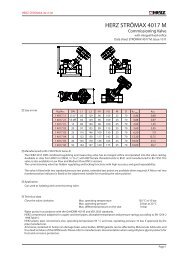
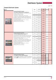
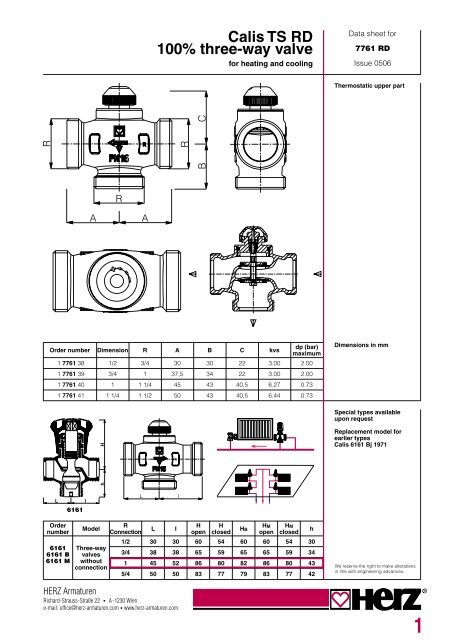
3Maximum operating temperature 120 °CMinimum operating temperature 2 °CMaximum operating pressure DN 15, 20 10 barMaximum operating pressure DN 25, 32 16 barMaximum pressure drop for thermostatic operation 0.2 barHeating water quality according to ÖNORM H 5195 or VDI guideline 2035.Ammonia contained in hemp damages brass valve body. The mineral oils or lubricants containingmineral oils lead to the swelling and therefore to the damage of EPDM seals. Frost and corrosionprotectors based on ethylene glycol are allowed in 15 - 45 % percentage. All specified informationsare to be found in standard specification sheets.When using HERZ compression unions for copper and steel pipes, the permissible temperatureand pressure information according to EN 1254-2:1998 table 5 must be noted. For plastic pipeconnectors a maximum operating temperature of 80 °C and a maximum operating pressure of 4 barapply, according to the pipe manufacturer’s specifications.Operating dataNominalvalues7761Connectionthread,flat sizesealingfor pipeIron pipeSolderedconnectionfor pipeWeldedconnectionfor pipePress connectionfor pipePipe connectionDN 153/41/21 6220 21121 6236 01211 6240 0114 x 2.0P 7014 41DN 15 3/41/2 x 38 mm1 6220 11151 6236 1116 x 2.0P 7016 41DN 15 3/41/2 x 44 mm1 6220 22181 6236 2118 x 2.0P 7018 41DN 15 3/420 x 2.0P 7020 41DN 15 3/420 x 2.5 P 7021 41DN 20 13/4 1 6220 12 15 1 6236 02 26.5 1 6240 02 16 x 2.0 P 7016 42DN 20 1Reduction 1/2 1 6220 02 18 1 6236 12 Reduction 21 1 6241 02 18 x 2.0 P 7018 42DN 20 122 1 6236 22 20 x 2.0 P 7020 42DN 20 120 x 2.5 P 7021 42DN 20 125 x 2.5 P 7025 42DN 20 125 x 3.5 P 7024 42DN 20 126 x 3.0 P 7026 42DN 25 1 1/41 1 6220 63 28 1 6236 63 33.7 1 6240 63 25 x 2.5 P 7025 43DN 25 1 1/425 x 3.5 P 7024 43DN 25 1 1/426 x 3.0 P 7026 43DN 25 1 1/432 x 3.0 P 7032 43DN 25 1 1/440 x 3.5 P 7040 43DN 32 1 1/21 1/4 1 6220 64 35 1 6236 64 47.5 1 6240 64 32 x 3.0 P 7032 44DN 32 1 1/240 x 3.5 P 7040 44DN 32 1 1/250 x 4 P 7050 44Nuts, connectors and seals are always included in the delivery of HERZ flat-seal connector screws.HERZ Calis TS RD 100 distributor valves are suitable for use as thermostatic control valves forconstantly maintaining room temperature or average temperature in closed cold and hot watercircuits with almost constant volume flows.In the open condition of the thermostatic valve, the through port of the valve is open, and the valve isclosed by a thermostat or a thermal drive, when the branch is open and the through port is closed.FunctioningThe CALIS-TS upper part (DN 15 and DN 20 ) can be changed under pressure by means the HERZChangefix Tool 1 7780 00. Thus faults can be easily rectified at the seal, e.g. from the residue offoreign bodies such as dirt, welding and soldering remains, which can be easily removed. Whenusing the HERZ Changefix tool, the instructions included should be noted.Changing thethermostatic valveupper parts
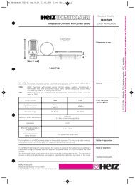
To control the thermostatic upper part all HERZ thermostats with application or immersion sensor aswell as the components of the HERZ RTC electronic control systems (room temperature computer,DDC actuator) and HERZ RTR (room thermostats and thermo-motors) can be used.Thermostatic operationTo avoid sticking, the valve spindle of the thermostatic upper part is protected from deposits by asecond O ring.Two O-rings serve as spindle seals, and these are fitted in an replaceable brass chamber. TheO-rings guaranteed maximum freedom from maintenance and offer lasting ease of movement of thevalve.Changing the O-ring1. Remove the HERZ thermostatic head or drive.2. Now the O-ring chamber including the O-ring is unscrewed and replaced with a new one.The upper part must be held with a spanner during this change procedure. With the dismantlingthe valve is automatically completely opened and therefore re-sealed, but some drops of watermay escape.3. Re-assembly in reverse order. When placing the HERZ TS hand wheel, it should be turned to testwhether the valve closes.Spindle seal1 6890 00 O-ring setSeat sealThe valve is fitted with a soft seal, which is constructed for the demands of thermostatic operation.The screw cap serves to activate during the building phase (pipe flushing). By removing thescrew cap and mounting the HERZ thermostatic head the thermostatic valve is complete withoutdraindown.HERZ thermostatic valveNominal strokeAdjustment of the nominal stroke using the screw cap:On the periphery of the screw cap in the area of the knurling, there are two adjustment markings(raised) with the markings “+” and “-”1. Close the valve using the screw cap by turning it clockwise.2. Marking that position that corresponds to the adjustment marking “+”.3. Turn the screw cap anti-clockwise until the adjustment marking “-” is located at the 2nd markedposition.In the unlikely event that a HERZ thermostatic valve lower part is not fitted with a HERZ thermostatichead the HERZ-TS hand wheel 1 9201 80 replaces the screw cap.HERZ-TSHand wheelThe thermostatic valve lower part is mounted in the flow pipe with a flow in the direction of thearrow (shown on the casing).Installationflow directionradiatorbypass1 7420 06 HERZ thermostat with contact sensor 20 - 50 °C1 7420 16 HERZ thermostat with contact sensor 20 - 50 °C1 7421 00 HERZ thermostat with contact sensor 40 - 70 °C1 9421 26 HERZ thermostat with contact sensor 30 - 60 °C1 6313 01 Immersion pocket for contact sensor1 1001 02 T-piece, DN 20Accessories1 7760 38-180 Replacement upper part for Calis RD DN 15 and DN 20.For <strong>Valves</strong> 1 7760 40 and 41 the spare upper parts are not availableReplacement part4
HERZ Standard diagramHERZ Calis TS RDOrder number 7761 Dim. DN 15 R = 1/2 • DN 20 R = 3/4The valve construction [∆ p] corresponds to the “German Power Transmission Engineering Association instructions on planning andhydraulic balancing of heating equipment instructions on planning and hydraulic balancing of heating equipment with thermostaticradiator valves”.Flow characteristics 1 7761 40/41(Independent for flow path)We reserve the right to make modifications in line with progress in engineeringHERZ ArmaturenRichard-Strauss-Straße 22 • A-1230 Wiene-mail: office@herz-armaturen.com • www.herz-armaturen.com5
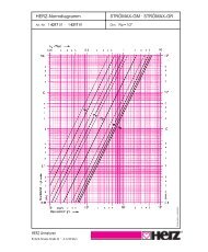
HERZ standard diagramHERZ Calis TS RDOrder number 1 7761 40 • 1 7761 41 Dim. DN 25 • DN 32, DN 20The valve construction [∆ p] corresponds to the “German Power Transmission Engineering Association instructions on planning andhydraulic balancing of heating equipment instructions on planning and hydraulic balancing of heating equipment with thermostaticradiator valves”.Flow characteristics 1 7761 40/41(Independent from pass or branch pipe direction)We reserve the right to make modifications in line with progress in engineeringHERZ ArmaturenRichard-Strauss-Straße 22 • A-1230 Wiene-mail: office@herz-armaturen.com • www.herz-armaturen.com6