PDF Download - Herz Valves UK
PDF Download - Herz Valves UK
PDF Download - Herz Valves UK

You also want an ePaper? Increase the reach of your titles
YUMPU automatically turns print PDFs into web optimized ePapers that Google loves.
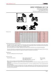
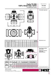
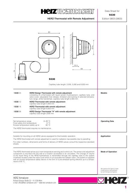
HERZ-Thermostat with Remote AdjustmentData Sheet for9330Edition 0803 (0803)80HERZ-Thermostatkopf5480Ø5423,3689330Capillary tube length: 2,000, 5,000 and 8,000 mm19330 05 HERZ-Design Thermostat with remote adjustmentconsisting of a thermostat with liquid sensor (hydrosensor), capillary tube, andvalve cover; adjustable frost release, limitation and locking of selected temperaturerange, white handwheel, capillary tube length 2,000 mm.19330 10 HERZ-Thermostat with remote adjustmentcapillary tube length 5,000 mm19330 18 HERZ-Thermostat with remote adjustmentcapillary tube length 8,000 mm19330 98 HERZ-Design Thermostat "H" with remote adjustmentcapillary tube length 2000 mmModelsSet temperature range 6–28 °CFrost safety limit temperature 6 °CExcess temperature safety up to 60 °CThe HERZ-thermostat requires no maintenance.Operating DataSuitable for mounting on all HERZ-valves equipped for thermostatic operation.The HERZ-thermostat with remote adjustment is used for radiators inaccessible due to panelling.For order numbers, dimensions and forms of delivery of HERZ-valves consult the respective standardsheets.ApplicationThe HERZ-thermostat serves as a room temperature sensing and control unit. The sensor and adjustmentcomponent is mounted onto the wall at a location accessible to air circulation. The change of volumeof the liquid filling of the HERZ-hydrosensor is transmitted through the capillary tube to the systemof bellows located under the valve cover which in turn actuates the radiator valve. The system is suppliedwith an excess temperature safety device in the form of a pre-stressed spring effective up to a temperatureof 60 °C.Mode of OperationWe reserve the right to makemodifications necessitatedby technological progress.HERZ ArmaturenRichard-Strauss-Straße 22 • A-1230 Wiene-mail: office@herz-armaturen.com • www.herz-armaturen.com1®
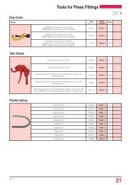
Turning the sensor and adjustment component anti-clockwise increases the room temperature,turning it clockwise reduces the temperature.SettingsComfort PointThe comfort point “ ” is located between the marks “3” and “4”. It corresponds to a room temperatureof approximately 20 °C. This means optimum heating comfort and energy saving.Frost ReleaseAt position "✳ " the valve opens automatically to prevent a freezing installation.Summer SettingAfter the end of the heating period, open thermostats completely by turning anti-clockwise to preventthe formation of dirt deposits at the valve seat.The adjustment marks roughly correspond to the room temperatures specified below. Deviations ofa few degrees (K) are possible according to the mode of installation and design of the heating system.Adjustment MarksMarks I ✳ 1 2 3 4 5 6approx. °C 6 9 11 14.5 18 20 21 24.5 2817555 00 20 retaining clips for capillary tube installation19551 00 Limiting pin, for limiting and locking of the set value range for HERZ-thermostaticheads of series 9000 (to be ordered separately).AccessoriesThe capillary tube must not be bent sharply or damaged during installation because this would impairits function. The tube must not be installated on or near heating piping, radiators or other heatsources.It must be ensured that the sensor and adjustment component at the wall is not covered by anycurtains, panelling, etc.Important for Installation2
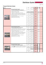
Installation1. Unscrew cap or handwheel from the thermostaticvalve (fig. 1).2. Place valve cover on top of the thermostatic valve andtighten the union nut manually (fig. 2).2. The capillary tube can be embedded in the existingslot (fig. 3).3. Use the fastening material supplied with the thermostatto mount the thermostatic element onto thewall in such a way that the arrow on the bottom plate(beside the colour mark) points upward. Take intoaccount the capillary tube length when mounting thethermostat (fig. 4).1 24. If the capillary tube is too long, the part which is notneeded can be wound up on the botton plate (fig. 5).2. If the tube is not laid behind panelling, starting boards,etc. it can be mounted by means of retaining clips(order No. 17555 00). For buried laying see item 6.5. Snap cover plate into position in such a way that thepointer matches with the bottom plate arrow pointingupward (fig. 6).3 46. Buried Laying of the Capillary Tube2. The thermostatic element with bottom plate can alsobe mounted on flush boxes.2. The bellows located inside the valve cover are passedthrough a pipe (inside diameter 23 mm). For this purpose,the plastic components must be disassembledas described below (fig. 7).2. ● Push the union nut back;2. ● Widen the slotted sleeve and pull the insulationcomponent plus bellows out;2. ● Then, remove all 3 plastic components.After introduction into the pipe (fig. 8), slide the 3 plasticcomponents on again into their correct positions startingwith the union nut. The insulation component must snapinto the slotted sleeve (fig. 9).Mount the valve cover on the thermostatic valve asdescribed above.5 67 8Adjustment OptionsAt the bottom plate there are 2 steel pins which serve forlimiting the set temperature range. Locking at a given settemperature is also possible.9 10Procedure:● Remove cover plate● Set the desired temperature● Place a pin either before or after the handwheel stopdepending on whether the set value is intended to bea minimum or maximum temperature (fig. 10, 11).● Snap cover plate into position as in item 5.In order to lock the set temperature at a given value useboth pins placing them directly before and after thehandwheel stop (fig. 12).11 12301-ZD-06/03