Surface Roughness Produced by Hard Turning With Pcbn Tools
Surface Roughness Produced by Hard Turning With Pcbn Tools
Surface Roughness Produced by Hard Turning With Pcbn Tools

Create successful ePaper yourself
Turn your PDF publications into a flip-book with our unique Google optimized e-Paper software.
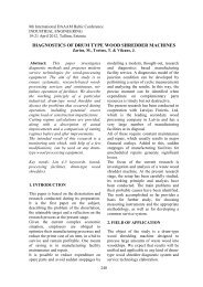
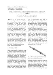
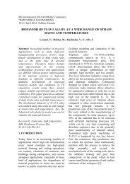
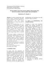
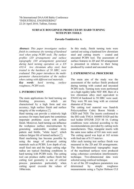
7th International DAAAM Baltic Conference<br />
“INDUSTRIAL ENGINEERING”<br />
22-24 April 2010, Tallinn, Estonia<br />
SURFACE ROUGHNESS PRODUCED BY HARD TURNING<br />
WITH PCBN TOOLS<br />
Zawada-Tomkiewicz A.<br />
Abstract: This paper investigates surface<br />
finish in continuous dry turning of hardened<br />
steel when using PCBN tools. The surface<br />
profiles (2D arrangement) and surface<br />
topography (3D arrangement) generated<br />
during hard turning operation on a EN<br />
41Cr4 low chromium alloy steel, heat<br />
treated to the hardness of 58 HRC, were<br />
evaluated. This paper introduces the multiparameter<br />
characterization of the surface<br />
when cutting with different tool materials.<br />
Key words: hard turning, surface<br />
roughness, PCBN tools.<br />
1. INTRODUCTION<br />
The main applications for hard turning are<br />
finishing processes, which are<br />
characterised <strong>by</strong> a high form and size<br />
accuracy, high surface finish and surface<br />
integrity of the workpiece [ 1 ].<br />
<strong>Hard</strong> turning can provide a relatively high<br />
accuracy for many hard parts but sometimes<br />
important problems occur with surface<br />
finish. Moreover, hard turning can influence<br />
the workpiece surface microstructure <strong>by</strong><br />
generating undesirable residual stress<br />
pattern and brittle, "white layer", which<br />
reduces fatigue life of turned surfaces [ 2 ].<br />
<strong>Hard</strong> machining has become possible <strong>by</strong><br />
using the range of advanced cutting<br />
materials such as PCBN. Low depth of cut,<br />
small feed rate and the large cutting edge<br />
radius are typical finishing conditions in<br />
hard turning with PCBN tools. The cutting<br />
tool can produce stable surface finish but<br />
cutting tool geometry is one of critical<br />
process parameters particularly when<br />
cutting speed exceeds the values of<br />
100m/min.<br />
In this study, finish turning tests were<br />
carried out using a hardened low chromium<br />
steel and cutting inserts – coated and<br />
uncoated PCBN tool. The assessment of<br />
surface features in 2D and 3D arrangement<br />
is presented in relation to their being<br />
produced <strong>by</strong> coated and uncoated tools.<br />
2. EXPERIMENTAL PROCEDURE<br />
The main aim of the study was the<br />
assessment of the surface finish produced<br />
during turning with coated and uncoated<br />
PCBN tools. <strong>Turning</strong> tests were performed<br />
on a high rigidity lathe NEF 400. Bars of a<br />
low chromium alloy steel equivalent to<br />
EN41Cr4 hardened to 58 HRC were used.<br />
They were 90 mm long with an external<br />
diameter of 26 mm.<br />
The cutting tool material was Sandvik<br />
Polycrystalline Cubic Boron Nitride -<br />
CB20 and 7020. The inserts conformed to<br />
the ISO code TNGA 160408 S1020 and the<br />
tool holder DTGNR 2525 M 16. Cutting<br />
conditions were selected according to the<br />
recommendations provided <strong>by</strong> cutting tools<br />
manufacturers. Thus, triangular inserts with<br />
the same nose radius of 0.8 mm were used.<br />
The cutting speed was kept at 165 m/min<br />
with feed rate of 0.15 mm/rev.<br />
After each turning test surface finish was<br />
measured in the 2D and 3D arrangements.<br />
The three-dimensional topographic maps<br />
of the machined surfaces were produced<br />
using coherence correlation interferometry<br />
technique. Two-dimensional data were<br />
selected using confocal technique.<br />
A set of the 2D roughness parameters was<br />
determined <strong>by</strong> simple roughness<br />
measurements using a Taylor Hobson CLI
2000 instrument. Moreover, 3D<br />
measurements were carried out <strong>by</strong> means<br />
of Talysurf CCI 6000 profilometer. In<br />
consequence, the analysis of the surface<br />
geometrical structures was done using both<br />
profiles and 3D topographies of the<br />
surface. Both 2D and 3D parameters, were<br />
taken into account [ 3 , 4 ].<br />
3. RESULTS AND DISCUSSION<br />
3.1. Tool geometry and wear<br />
For cutting tests, uncoated and coated (with a<br />
TiN layer, 1 µm thick) inserts were selected.<br />
Geometry of both wedges was similar (chamfer<br />
normal rake angle γn = –20°, chamfer width: 0.1<br />
mm, honing edge radius = 0.03 mm). The<br />
cutting edge inclination angle of the insert is λs<br />
= –6°, and the normal rake angle was γn = –6°.<br />
Wedges underwent analysis in the initial<br />
phase of their work, when the tool nose was<br />
still coated with the TiN layer. The wedges<br />
cut for 48m, which took 18 seconds of<br />
cutting. After this time durability of the<br />
wedge was not distorted, the wear rate was<br />
insignificant and occurred only on the main<br />
flank. Figure 1 presents a view of the flank<br />
from the wedge’s side.<br />
Fig. 1. Tool flank wear for CB20 (a) and 7020 (b)<br />
cutting tool material<br />
In case of CB20 the wedge’ wear was almost<br />
unnoticeable. For 7020 wedge the wear is<br />
outlined <strong>by</strong> the changeability of material<br />
properties in SEM images. Nonetheless, the<br />
change in tool geometry is visible only in the<br />
area of tool edge rounding.<br />
3.2. Machined surface<br />
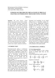
Theoretical research on surface roughness<br />
focuses on kinematic-geometric mapping of<br />
tool nose. Cutting takes place through part<br />
of the rounded tool nose. The value of tool<br />
nose radius determines an almost flat stretch<br />
parallel to the surface of a length similar to<br />
the value of the feed rate (Fig.2).<br />
Fig. 2. Schema of producing machined surface and<br />
machined surface image<br />
Theoretical roughness, calculated for cutting<br />
conditions, is estimated to be 0.807µm. The<br />
measured roughness is higher than the<br />
theoretical value. The reason of that is the<br />
minimal irremovable layer of the cut<br />
material. When the wedge is unable to<br />
remove the material then it is deformed or<br />
removed as microcutting, scratching or<br />
ploughing. During microcutting furrows are<br />
detected in the machined material through<br />
exposition of unevenness of the cutting<br />
edge, which goes into the material, cuts its<br />
parts off during relative movement, piles<br />
them up and tears them off. Scratches<br />
appear in the machined material because of<br />
the protruding element of unevenness of the<br />
cutting edge. The phenomenon of scratching<br />
is a transitional stage. Ploughing is<br />
indenting projection of the cutting edge into<br />
the machined material and plastic<br />
expression of a furrow in it during the<br />
relative movement. The material expressed<br />
from the furrow is piled up along one of its<br />
sidewalls. Figure 2 presents the image of<br />
machined surface produced in turning with<br />
PCBN tools. Development of machined<br />
surface demonstrates very different<br />
mechanisms when considering coated and<br />
uncoated wedges. Further considerations<br />
concern the description of the development<br />
of machined surface in 2D and 3D<br />
arrangements.<br />
3.3. <strong>Surface</strong> roughness analysis – 2D<br />
Due to repeatability of the profile at the<br />
distance of the feed rate’s value, part of the<br />
profile of a feed rate length can be<br />
distinguished in such a way that ‘outline of<br />
the wedge’ – the basic shape of<br />
unevenness, is obtained (Fig.3).
Fig. 3. Machined surface roughness profile<br />
Comparing proportions of heights of the<br />
unevenness with length of the basic shape<br />
of unevenness - 5 µm of height to 150 µm<br />
of length of the feed rate - it can be noticed<br />
that it is a tiny, almost flat part of the<br />
wedge, which is printed on the surface and<br />
which remains unchanged for a long time –<br />
despite change of the wedge’s geometry of<br />
the main flank and rake face.<br />
Fig. 4. Machined surface roughness and waviness<br />
profiles and parameters<br />
Analysis of roughness profiles created <strong>by</strong><br />
CB20 and 7020 cutting tools makes<br />
observation of differences (Fig.4). The initial<br />
phase of cutting is very similar; parameters<br />
are almost identical. The lesser change of<br />
cutting tool geometry influenced the surface<br />
roughness profile. Rt parameter increased<br />
nearly 1µm so that the averaged value for the<br />
whole profile is equal to 5.27µm.<br />
Analysis of surface waviness profile<br />
demonstrates significant differences for all<br />
the parameters. Differences in this case<br />
take from the difficulties in cutting with<br />
negative rake angle and large and<br />
developed cutting edge.<br />
3.4. <strong>Surface</strong> roughness analysis – 3D<br />
Analysis of topography displayed in Figure<br />
5 demonstrates for both of the cases very<br />
smooth surface. The ridges after the tool<br />
pass are almost identical. The range of<br />
height is approximate, though it is smaller<br />
for the surface shaped <strong>by</strong> the coated wedge.<br />
The differences are barely noticeable for<br />
most of the amplitude, area & volume, and<br />
spatial parameters. Therefore, their<br />
description is omitted.<br />
Observation of the contour maps of the<br />
surface and then the layout of the unevenness<br />
shows visible differences. Concentration of<br />
lines and points on the contour map is<br />
different. Greater randomness of the surface<br />
is visible especially in case of surface created<br />
<strong>by</strong> uncoated wedge where cutting edge is<br />
more developed. To describe the visible<br />
differences more thoroughly several<br />
parameters was chosen (Fig.5).<br />
Mean material volume ratio (Smmr) was<br />
selected as the first parameter. It is a<br />
parameter describing the total volume of<br />
material of the surface obtained <strong>by</strong><br />
measuring the space between an imaginary<br />
horizontal plane at the minimum altitude of<br />
the surface and the points of the surface.<br />
The higher value of Smmr for CB20 cutting<br />
tool material (>3µm 3 /µm 2 ) indicates that in<br />
this case the material volume will be<br />
subjected to higher wear.<br />
Density of summits (Sds), and root-meansquare<br />
slope (Sdq) were selected for the<br />
reason that they are able to describe the
susceptibility to abrasive wear. Values of<br />
parameters for uncoated tools are nearly<br />
twice the coated. These and subsequent<br />
parameters confirm greater complexity of<br />
machined surface for CB20 than 7020.<br />
In general, hard turning with PCBN tools<br />
provide very smooth and uniform surface.<br />
<strong>Hard</strong> turned surfaces in both cases were<br />
produced with the positive values of<br />
skewness and kurtosis less than 3.<br />
Differences were better distinguished in<br />
waviness profile and parameters.<br />
Complexity of the textures for both<br />
surfaces was described with five different<br />
parameters. 3D images and adequate<br />
contour maps of the surfaces generated <strong>by</strong><br />
hard turning allow distinguishing mixedanisotropic<br />
textures when the random part<br />
was significantly greater for CB20 cutting<br />
tool material.<br />
6. REFERENCES<br />
Fig. 5. Topography images and parameters of<br />
machined surface<br />
Arithmetic mean summit curvature (Ssc)<br />
enables to know the mean form of the<br />
peaks: either pointed, either rounded,<br />
according to the mean value of the<br />
curvature of the surface at these points. The<br />
value of Ssc for CB20 cutting tool material<br />
is greater and increases with cutting time.<br />
Developed interfacial area ratio (Sdr)<br />
describes the complexity of the surface<br />
thanks to the comparison of the curvilinear<br />
surface and the support surface. A<br />
completely flat surface has a Sdr near 0%.<br />
Sdr is of 33.1% for CB20 cutting tool<br />
material and only 9.41 for 7020 cutting<br />
tool material. The difference increases with<br />
cutting time.<br />
5. CONCLUSIONS<br />
Based on the experimental results, 2D and<br />
3D parameters of the surface produced <strong>by</strong><br />
hard machining with PCBN coated and<br />
uncoated tools were selected and analysed.<br />
1. Zawada-Tomkiewicz A., Application of<br />
machined surface image analysis for<br />
identification of suitable parameters of<br />
turning as a pre-operation, 12th<br />
International Conference on Metrology and<br />
Properties of Engineering <strong>Surface</strong>s,<br />
Rzeszow 2009 167-171<br />
2. W. Grzesik, T. Wanat, Comparative<br />
assessment of surface roughness produced<br />
<strong>by</strong> hard machining with mixed ceramic<br />
tools including 2D and 3D analysis,<br />
Journal of Materials Processing<br />
Technology 169 2005 364–371<br />
3. W.P. Dong, P.J. Sullivan and K.J. Stout,<br />
Comprehensive study of parameters for<br />
characterizing three dimensional surface<br />
topography. III. Parameters for<br />
characterizing amplitude and some<br />
functional properties, Wear 178 1994 29–43<br />
4. Stout, K.J., Sullivan, P.J., Dong, W.P.,<br />
Mainsah, E., Luo, N., Mathia, T.,<br />
Zahouani, H. 1994, The Development of<br />
Methods for the Characterisation of<br />
<strong>Roughness</strong> in Three Dimensions,<br />
Publication no. EUR 15178 EN of the<br />
Commission of the European<br />
Communities, Luxembourg, ISBN 0 7044<br />
1313 2:1-358