ANALYSIS OF THERMOELASTIC STRESSES IN LAYERED PLATES
ANALYSIS OF THERMOELASTIC STRESSES IN LAYERED PLATES
ANALYSIS OF THERMOELASTIC STRESSES IN LAYERED PLATES

You also want an ePaper? Increase the reach of your titles
YUMPU automatically turns print PDFs into web optimized ePapers that Google loves.
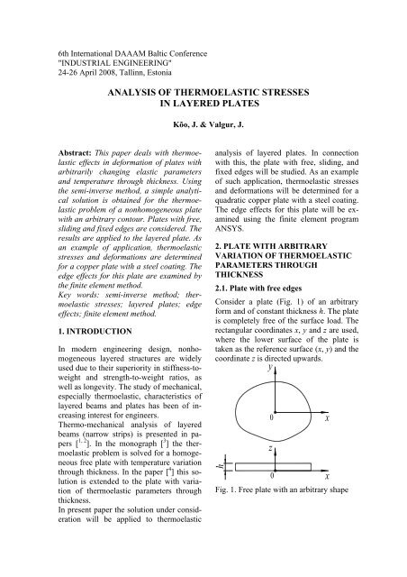
6th International DAAAM Baltic Conference"<strong>IN</strong>DUSTRIAL ENG<strong>IN</strong>EER<strong>IN</strong>G"24-26 April 2008, Tallinn, Estonia<strong>ANALYSIS</strong> <strong>OF</strong> <strong>THERMOELASTIC</strong> <strong>STRESSES</strong><strong>IN</strong> <strong>LAYERED</strong> <strong>PLATES</strong>Kõo, J. & Valgur, J.Abstract: This paper deals with thermoelasticeffects in deformation of plates witharbitrarily changing elastic parametersand temperature through thickness. Usingthe semi-inverse method, a simple analyticalsolution is obtained for the thermoelasticproblem of a nonhomogeneous platewith an arbitrary contour. Plates with free,sliding and fixed edges are considered. Theresults are applied to the layered plate. Asan example of application, thermoelasticstresses and deformations are determinedfor a copper plate with a steel coating. Theedge effects for this plate are examined bythe finite element method.Key words: semi-inverse method; thermoelasticstresses; layered plates; edgeeffects; finite element method.1. <strong>IN</strong>TRODUCTIONIn modern engineering design, nonhomogeneouslayered structures are widelyused due to their superiority in stiffness-toweightand strength-to-weight ratios, aswell as longevity. The study of mechanical,especially thermoelastic, characteristics oflayered beams and plates has been of increasinginterest for engineers.Thermo-mechanical analysis of layeredbeams (narrow strips) is presented in papers[ 1, 2 ]. In the monograph [ 3 ] the thermoelasticproblem is solved for a homogeneousfree plate with temperature variationthrough thickness. In the paper [ 4 ] this solutionis extended to the plate with variationof thermoelastic parameters throughthickness.In present paper the solution under considerationwill be applied to thermoelasticanalysis of layered plates. In connectionwith this, the plate with free, sliding, andfixed edges will be studied. As an exampleof such application, thermoelastic stressesand deformations will be determined for aquadratic copper plate with a steel coating.The edge effects for this plate will be examinedusing the finite element programANSYS.2. PLATE WITH ARBITRARYVARIATION <strong>OF</strong> <strong>THERMOELASTIC</strong>PARAMETERS THROUGHTHICKNESS2.1. Plate with free edgesConsider a plate (Fig. 1) of an arbitraryform and of constant thickness h. The plateis completely free of the surface load. Therectangular coordinates x, y and z are used,where the lower surface of the plate istaken as the reference surface (x, y) and thecoordinate z is directed upwards.Fig. 1. Free plate with an arbitrary shape
The plate is fixed at the origin of the coordinates,where deflection and its derivationsare zero, i.e. ∂ uz∂uzuz= = = 0 .∂x∂yThe temperature T, the coefficient of linearthermal expansion α, the modulus of elasticity(Young’s modulus) E and the Poisson’sratio μ vary through thickness only,=E = E z andi.e. T T( z ), α=α( z ), ( )μ = μ ( z). By analogy with the homogeneousplate [ 3 ], it is reasonable to assume thatthe stress components will be of the followingform:σx= σy= σ ( z)⎪⎬ ⎫. (1)σz = τxy = τyz= τzx= 0⎪⎭These stresses satisfy identically the followingequilibrium equations of the theoryof elasticity [ 3, 5 ]:∂σ∂τx yx ∂τxz+ + = 0 (x, y, z). (2)∂x ∂y ∂zHere and below the symbol (x, y, z) denotespermutation by means of which wecan write two more equations correspondingto the other two axes, changing x for y,y for z, and z for x.From the thermoelastic stress-strain relations[ 3, 5 ]1ε = ⎡ − ( + ) ⎤⎣σ μ σ σ⎦+ α T (3)xEx y z (x, y, z)we haveσ ⎫εx= εy= ε( z) = + αT*E ⎪⎬ , (4)2με =− + ⎪zσ αTE⎪⎭where* EE = (5)1 − μis the biaxial elastic modulus.For strains (4) the compatibility equations[ 3, 5 ]∂ ∂ ε ∂ γ∂y ∂x ∂x∂yare reduced to2 2 2εx y xy+ − = 02 2(x, y, z) (6)2∂ ⎛ σ ⎞+ T = 0.2 *∂z⎜⎝Eα ⎟⎠(7)Therefore*σ = E − α T + az+b , (8)( )where the constants a and b are to be determinedfrom the boundary conditions ofzero resultant force and moment on theedges of the plate.These conditions are reduced to:h∫h∫σdz= σ zdz = 0.(9)0 0Substitution of expression (8) yields thetwo equations for the unknown constants aand b. From these equations we find:CNT− BMT⎫a =2C − BD ⎪⎬ , (10)CMT− DNTb =⎪2C − BD ⎭⎪where the quantities N T , M T , B, C and D aredefined as follows:h⎫*NT= ∫ E αTdz⎪0 ⎪⎬⎪; (11)h*MT= ∫ E αTzdz⎪0 ⎭h⎫*B= ∫ E dz ⎪0 ⎪⎪⎪CDh*= ∫ E zdz ⎬0 ⎪⎪⎪h* 2= ∫ E z dz0. (12)⎪⎭The displacements u x , u y and u z in the x, yand z directions, respectively, are obtainedby using equations [ 3, 5 ]∂uxεx= (x, y, z) (13)∂ xand (4) as well as (8). The solution is thenfound to be:ux= x( az+ b)⎪⎬ ⎫; (14)uy= y( az+ b)⎪⎭
a 2 2uz=− ( x + y ) +2z(15)⎡ 2μ1+μ ⎤+ ∫ ⎢− ( az + b)+ α T .1−1−⎥dz0 ⎣ μμ ⎦For completeness of the solution, we determinethe deformation characteristics ofthe reference surface (z = 0). Using equations(14) and (13) we have for strain onthe reference surface:ε( 0) ≡ ε0=b . (16)In the case of small deflections we can usefor curvatures the approximations:22∂ uz∂ uzæx = ; æ ∂2 y= .2x ∂ yThen, using equation (15) we find the curvaturesof the reference surfaceæx = æy ≡ æ0=−a. (17)Thus, the plate subjected to a uniform temperaturechange is bent to a spherical surface.2.2. Plate with sliding edgesFor a plate with sliding edges (Fig. 2), wecan suppose that∂uz∂uzuz= 0 , = = 0∂x∂yfor every point of the reference surface.Fig. 2. Plate with sliding edgesThen a = 0 and from equations (10) it followsthatNb = T(18)Band expression (8) for stresses is reduced to*σ = E − α T + b . (19)( )2.3. Plate with fixed edgesFor a plate with fixed edges (Fig. 3), wecan start from the assumptions that∂uz∂uzux = uy = uz=0 , = = 0∂x∂yon the reference surface.Fig. 3. Plate with fixed edgesThen a = b = 0 and equation (8) for stressesis reduced to*σ =−E α T . (20)3. <strong>LAYERED</strong> PLATE SUBJECTED TOA UNIFORM TEMPERATURECHANGE3.1. Plate with free edgesConsider a layered plate (Fig. 4) consistingof an arbitrary number n of layers with differentconstant thicknesses h i .Fig. 4. Layered plateThe location of an arbitrary layer i of theplate is specified by the coordinate z i ,which is the distance from the bottomplane of the plate to the top plane of the ithlayer. Assume that the coefficient of thermalexpansion α i , the modulus of elasticityE i and the Poisson’s ratio μ i do not changethrough the thickness of the ith layer. Then,assuming that the plate is subjected to auniform temperature change ΔT, and usingpiecewise integration, we can write the parametersN T , M T , B, C and D in equations(11) and (12) asnn* * ⎫NT =ΔT∑Eiαi( zi− zi−1)=ΔT∑Eiαihi⎪ i= 1 i=1 ⎪⎬;(21)nΔT* 2 2M = ( −−1)⎪T ∑Eiαizi zi2 i=1⎪⎭
⎫B E z z E hnn* *= ∑ i ( i−i−1) = ∑ i i⎪ i= 1 i=1 ⎪⎪n1 * 2 2= ∑ i ( i−i−1) ⎬2 i=1⎪⎪n1 * 3 3= ∑ i ( i−i−1) ⎪3 i=1⎭C E z zD E z z. (22)For the constants (10) we havea = aΔT ; b= bΔT ,whereCNT− BMT⎫a =2C − BD⎪ ⎬ . (23)CMT− DNTb =⎪2C − BD ⎭⎪Herenn* * ⎫NT = ∑Eiαi( zi − zi−1)= ∑Eiαihi⎪ i= 1 i=1 ⎪⎬⎪. (24)n1 * 2 2MT = ∑Eiαi( zi −zi−1)2 i=1⎪⎭In accordance with equation (8) stresses inthe ith layer are*σ = E ΔT − α + az+b . (25)i i i( )Deformation parameters areε ⎫0= bΔT⎪ ⎬ . (26)æ0=−aΔT⎪⎭3.2. Plate with sliding edgesIn this case a = 0 , andNb = TB . (27)Stresses in the ith layer are*σ = E ΔT − α + b . (28)i i i( )Strain on the reference surfaceε = bΔT(29)0.3.3. Plate with fixed edgesFor this case a = b = 0 , and stresses in theith layer are*σ =−Eα ΔT.(30)i i i4. APPLICATIONS: THERMAL<strong>STRESSES</strong> DUE TO UNIFORMTEMPERATURE CHANGE <strong>IN</strong> ACOPPER PLATE WITH A GALVANICSTEEL COAT<strong>IN</strong>GUsually, the coefficients of thermal expansionof the substrate and coating are differentand the temperature of the coatingprocess differs from room temperature(+20°C). Therefore, thermal stresses aregenerated in coated parts. In experimentalanalysis of residual stresses it may turn outthat coating temperature differs from thetemperature at which the deformation parametersof the substrate are measured.In such cases measurement results have tobe corrected taking into account thermalstresses.As a numerical example, thermal stressesand displacements for a quadratic copperplate 30×30×1 mm with galvanic steelcoating deposited at 95°C are calculated.Fig. 5. Copper plate with a steel coatingIn addition, the following data is used: h 1 == 1.00 mm; E 1 = 110 GPa; μ 1 = 0.34; α 1 == 17.5 ⋅ 10 -6 1/°C for the substrate and h 2 == 0.26 mm; E 2 = 202 GPa; μ 2 = 0.28; α 2 == 14.3 ⋅ 10 -6 1/°C for the coating.
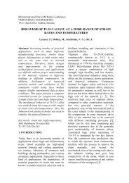
4.1. Plate with free edgesFor uniform temperature change ΔT == 20° – 95° = –75°C, the values defined byequations (5), (22) and (24) are:E * 1 = 166.7 GPa; E * 2 = 280.6 GPa;N = 3961 N/m; M = 2.638 N;TB = 239.66 ⋅ 10 6 N/m; C = 165.790 ⋅ 10 3 N;D = 149.10 N⋅m.By means of equations (23) we havea = -2.980 ⋅ 10 -3 1/m; b = 18.635 ⋅ 10 -6 .For stresses in layers from equation (25) itfollows that:* −3 −6σi = 75Ei ( αi+ 2.980⋅10 z−18.635⋅10)(i = 1, 2). (31)At typical points of thickness stresses inMPa are:σ1( 0)=−14.19 ( −13.51)⎫−3⎪σ1( 1⋅ 10 ) = 23.07 (23.62) ⎪ ⎪⎬. (32)−3σ2 ( 1⋅ 10 ) =−28.52 ( −27.56)⎪−3⎪σ2 ( 1.26⋅ 10 ) =−12.21 ( −11.32)⎪⎭From (26) for the strain and curvature ofthe reference surface we find−6 −6ε0=−1398⋅10 ( −1393.6⋅10 ) ⎫⎪ −3 −3 -1 ⎬ . (33)æ0=−216⋅10 ( −222.53⋅10 ) m ⎪⎭4.2. Plate with sliding edgesAccording to (27), we have b =16.528⋅10 -6and for stresses in layers (28) we obtain* 6σ = 75 ( −16.528⋅10 −iEi αi) (34)(i = 1, 2).From here for stresses in MPa we have:σ1= 12.15 (12.16) ⎫⎬ . (35)σ2=−46.89 ( −46.77)⎭Strain on the reference surface (29) has thevalue−6 −6ε 0=−1240⋅10 ( −1239.6⋅ 10 ) . (36)4.3. Plate with fixed edgesBy means of equation (30) we calculatestresses in the layers in MPa:σ1= 218.79 (218.7) ⎫⎬ . (37)σ2= 300.94 (300.8) ⎭T4.4. FEM analysisA similar problem was analysed by thefinite element program ANSYS. The obtaineddistribution of normal stress σ x == σ y = σ in the middle region of the plate ispresented in Fig. 6. The values of stressesat typical points of thickness are given inthe parentheses at the given data sets (32),(35) and (37). The values of the deformationparameters ε 0 and æ 0 are presented inthe same manner at the data sets (33) and(36). Comparison of the results shows thatdiscrepancy between data is less than 5%.Some results of stress analysis in the edgeregion (12.5 mm ≤ x ≤ 15 mm, y = 0, 0 ≤≤ z ≤ 1.26 mm) are presented in Fig. 7. Aswe can see, the normal stresses σ x = σ y = σin the edge region are reduced. The normalstress σ z , known as peeling stress, and theshear stress τ zx are highly localized near theedge. These facts once again confirm thevalidity of the well-known Saint-Venant’sprinciple.Fig. 6. Normal stresses σ x = σ y = σ (z) inthe middle region of a free copper platewith a steel coating
(a)(c)(b)(d)Fig. 7. Stress distributions in the edge region: (a) normal stress σ x , (b) normal stress σ y , (c)normal stress (peeling stress) σ z , (d) shear stress τ zx (MPa)5. CONCLUSIONS1. Using the semi-inverse method, an analyticalsolution is obtained for the thermoelasticproblem of a plate with an arbitrarycontour nonhomogeneous throughthickness. The results are applied foranalysis of a layered plate subjected to auniform temperature change.2. As an application, stresses due to uniformtemperature change in a copper platewith a galvanic steel coating are determined.3. Using the finite element method, thethermo-mechanical state of the same platewith the coating is studied. For the middleregion, good agreement is achieved betweenthe data of the analytical and numericalmethods. The data obtained withthe use of the finite element method forstresses in the edge region of the plate confirmthe validity of the well-known Saint-Venant’s principle.6. REFERENCES1. Feng, Z. C. and Liu, H. D. Generalizedformula for curvature radius and layerstresses caused by thermal strain insemiconductor multilayer structures. J.Appl. Phys., 1983, 54 (1), 83 – 85.2. Hsueh, C. H. Thermal stresses in elasticmultilayer systems. Thin Solid Films,2002, 418, 182 – 188.3. Boley, B. A. and Weiner, J. H. Theoryof Thermal Stresses. John Wiley andSons, Inc., New York, London, 1960.4. Kõo, J. P. Problem of thermoelasticityfor a free nonhomogeneous plate withtemperature variation through thickness.In Heat Stresses in StructuralMembers. Naukova Dumka, Kyiv,1979, 19, 89 – 91 (in Russian).5. Timoshenko, S. P., Goodier, J. N. Theoryof Elasticity. Third Edition.McGraw-Hill, Singapore, 1970.7. CORRESPOND<strong>IN</strong>G AUTHORProf. emer. Jakub KõoEstonian University of Life SciencesInstitute of Forestry and Rural EngineeringKreutzwaldi 5, Tartu 51014, Estonia,E-mail: jakub.koo@emu.ee