Impact Vibration Absorber of Pendulum Type
Impact Vibration Absorber of Pendulum Type
Impact Vibration Absorber of Pendulum Type

Create successful ePaper yourself
Turn your PDF publications into a flip-book with our unique Google optimized e-Paper software.
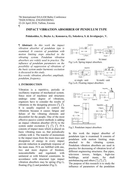
7th International DAAAM Baltic Conference"INDUSTRIAL ENGINEERING22-24 April 2010, Tallinn, EstoniaIMPACT VIBRATION ABSORBER OF PENDULUM TYPEPolukoshko, S.; Boyko A.; Kononova, O,; Sokolova, S. & Jevstignejev, V. Abstract: In this work the impactvibration absorber <strong>of</strong> pendulum type isexamined. It consists <strong>of</strong> pendulum withmotion limiting stops attached to thevibrating system. <strong>Pendulum</strong> vibrationabsorbers are widely used in practice. Theinfluence <strong>of</strong> pendulum parameters on thepossibility <strong>of</strong> suppression <strong>of</strong> vibrations <strong>of</strong>the basic system under harmonic excitationis discussed in this study.Key words: vibration, absorber, amplitude,pendulum, frequency.1. INTRODUCTION<strong>Vibration</strong> is a repetitive, periodic oroscillatory response <strong>of</strong> mechanical system.Since most <strong>of</strong> machines and structuresundergo some degree <strong>of</strong> vibrations,engineers have to consider the results <strong>of</strong>vibrations in the designing process [ 4 ], [ 8 ].It is usually required to control thevibrations because it causes fatigue andfailure <strong>of</strong> the vibrating elements anddiscomfort for the people. One <strong>of</strong> the mosteffective passive control methods is addingan impact vibration absorber (IVA) to thesystem under excitation [ 1 ], [ 2 ], [ 5 ]. IVAconsists <strong>of</strong> impact mass which is placed onbasic vibrating mass so, that periodicallycollides with it. The transfer <strong>of</strong> momentumto the impact mass from the main mass anddissipation <strong>of</strong> energy in every impactprovide reduction in amplitude response <strong>of</strong>the main mass. IVA are fulfilled with one,two and more degrees <strong>of</strong> freedom;noncontrollable and regulated; withunilateral or with bilateral constraints. Inaccordance with structural type impactvibration absorbers may be spring (Fig.1),floating (Fig.2) and pendular (Fig.3).a) outer b) innerFig.1.a-b. Spring impact absorbersa) single –unit b) multi –unitFig.2.a-b. Floating impact absorbersFig.3. <strong>Pendulum</strong> impact absorbersIn this work the impact absorber <strong>of</strong>pendulum type is examined. It consists <strong>of</strong>pendulum with motion limiting stopsattached to the vibrating system.<strong>Pendulum</strong> vibration absorbers are used inpractice for decreasing <strong>of</strong> vibration level <strong>of</strong>different engineering structures: flue pipes,television towers, bridges, high-risebuildings, aerial masts, for shaftautobalancing and others [ 3 ], [ 6 ], [ 8 ].The purpose <strong>of</strong> this research is to study theinfluence <strong>of</strong> parameters <strong>of</strong> the pendulum
on possibility <strong>of</strong> vibration suppression <strong>of</strong>the basic system under harmonicexcitation, and the effect <strong>of</strong> the systemparameters on system dynamics. Thisinvolved determination the effect <strong>of</strong> massratio, excitation amplitude, and clearancebetween impact stop walls. A pendulumwith one and two impacts during the periodis considered. Dependence <strong>of</strong> suppressionability <strong>of</strong> absorber on pendulum length,coefficient <strong>of</strong> restitution at impact, massratio <strong>of</strong> the basic system and pendulum,and gap size are found.2. ANALITICAL MODEL OFABSORBER2.1 Mathematical modelIn Fig.4 the models <strong>of</strong> single and doubleimpact pendulum absorbers are presented.a) single-impact absorber modelb) double impacts absorber modelFig.4. Model <strong>of</strong> the pendulum impact absorberParameters <strong>of</strong> system:m 1 – mass <strong>of</strong> the main body;m 2 - mass <strong>of</strong> the damper;μ= m 2 /m 1 - mass ratio;d – inherent damping coefficient <strong>of</strong> themain system;k – stiffness coefficient <strong>of</strong> main system;r - coefficient <strong>of</strong> restitution <strong>of</strong> the velocityafter impact;λ - natural frequency <strong>of</strong> the main system;ω – the frequency <strong>of</strong> pendulum;l - length <strong>of</strong> pendulum;c – size <strong>of</strong> gap;α - max angle for two-impacts absorber,tan α = c / l ;The system is considered under harmonicexcitation:P( t)= P0 sin Ωt,P 0 - amplitude <strong>of</strong> excitation force;Ω – frequency <strong>of</strong> excitation.2.2 The equations <strong>of</strong> motion <strong>of</strong> thesystemUsing Lagrange’s equations the equation <strong>of</strong>motion <strong>of</strong> the examined system is derived:⎧(m1+ m2) x + m2l ϕ cosϕ= −kx− dx+⎪∞⎪ 2+ m2l ϕ sinϕ+ P0sin Ωt− S∑δ( t − RT );⎪R=0⎨ 2⎪m2l ϕ + m 2xl cosϕ= −m2gl sinϕ+⎪ ∞⎪+S −∑δ( t RT )(1)⎩ R=0where:S - impact impulse,δ ( t − RT ) − delta function,T – period <strong>of</strong> collisions.The stereomechanical theory <strong>of</strong> impact isused for impact impulse definition [ 7 ]:m1m2S = ( 1+r)( v01− v02) (2)m1+ m2wherev 01 and v 02 - velocity <strong>of</strong> main body andvelocity <strong>of</strong> impactor just before impact.The velocity <strong>of</strong> impactor consists <strong>of</strong>translational velocity and relative velocity:v01 − v02= v01− ( v01+ v2r ) = −lϕ01,(3)here the angular velocity is pendulumvelocity just before impact, ϕ01= ϕ(T ) .Taking into account (3) impact impulsemay be represented as:m2 S = (1 + r)( −l ϕ). (4)1+µAfter rearrangement <strong>of</strong> equation <strong>of</strong> system(1) and taking into account (4) system (1)may be written:
2⎧ b λ µ 2⎪x + x+ x = l ϕ sinϕ−⎪1+µ 1+µ 1+µ⎪ µp0⎪−l ϕ cosϕ+ sin Ωt+⎪1+µ 1+µ⎪∞(1 + r)µ⎨+l ϕ(T ) ∑δ( t − RT );2⎪ (1 + µ )R=0⎪2 x⎪ϕ + ω sinϕ= − cosϕ−⎪l∞⎪ 1+r(5)⎪− ϕ(T ) ∑δ( t − RT )⎩1+µ R=0where:kλ = ,m 1db = ,m 1P0p0= ,m1gω = .l2.3 Analytical solution <strong>of</strong> the simplifiedequations <strong>of</strong> motionFor the simplified variant <strong>of</strong> equations <strong>of</strong>motion <strong>of</strong> the system – without taking intoaccount dissipation and inertias forces:∞⎧ k P0S⎪x + x = sin Ωt− ∑δ( t − RT)m m m R=0⎨(6)∞⎪ 2 x S ϕ + ω ϕ = − + −⎪∑δ( t RT ),⎩l m2lR=0where m=m 1 +m 2 , with help <strong>of</strong> method <strong>of</strong>fitting an analytical solution is found [ 6 ].Purely forced vibrations <strong>of</strong> the system andabsorber for a time domain (0, Т) betweenimpacts under conditions <strong>of</strong> tuning:ΩT=2π; 2ω= Ωfor resonance condition λ/(1+μ)= Ω:~ p 3( )0 ⎛ λtx t = cos2 ⋅ ⎜ −+2λ⎝ 2 1+µ⎛ 3 (1 2 )(1 )⎞ ⎞⎜π + µ − r λt− + ⎟λtπ sin ⎟,4 (1 ) 11+⎝ µ + r+ µ ⎠ µ ⎠~ 2 p ⎛0 (3 2 )( ) ⎜π − µϕ t = ⋅ sin23lλ⎝ 2µ2⎛⎜ 3π(1 + 2µ)(1 − r)−π+⎜⎝4µ(1 + r)λt−1+µλt⎞⎟sin1+µ⎠where the notations are as agreed above.(7)λt⎞⎟,1+µ ⎟⎠2.4 Numerical solution <strong>of</strong> equations <strong>of</strong>motionIn this work the numerical solution <strong>of</strong>system (5) was obtained with help <strong>of</strong> Eulermethod using the kinematics conditions –pre-impact and post- impact velocities <strong>of</strong>moving bodies if coefficient <strong>of</strong> restitutionis known. The velocity <strong>of</strong> the main body v1and velocity <strong>of</strong> impactor v 2 just afterimpact are:µ (1 + r)v1= v01+ l ϕ01. (8)1+µµ − rv2= v01+ l ϕ01. (9)1+µAlgorithm <strong>of</strong> Euler’s method for the sinleimpactdamper, taking into account (8),(9):tn+1 = tn+ ∆t,xnxnx+ 1=+n∆tϕn( ϕ + 1=n+ ϕn∆t)if ( ϕn≥ 0,0,1)µ (1 + r)xnxnxnt l + 1=+ ∆ + ϕnif ( ϕn≤ 0,1,0)1+µµ − r ϕ nϕ nϕnt + 1= + ∆ + ϕnif ( ϕn≤ 0,1,0)1+µ2b λ p0 xn1x+= −n− xn+ sin Ωtn1+µ 1+µ 1+µµ 2 µ+ l ϕnsinϕn− l ϕncosϕn1+µ1+µ2 xn ϕ= − ϕ sinϕ− cosϕn+1nlEuler method gives good results if timeinterval Δt is small. The equations <strong>of</strong>motion are solved numerically with help <strong>of</strong>Matcad program. The received resultsenable to analyze all parameters <strong>of</strong> motion<strong>of</strong> the system.Examples <strong>of</strong> the solution <strong>of</strong> motion arepresented below for single and two-impactabsorbers.3. NUMERICAL EXAMPLEFor the numeral solution next value <strong>of</strong>parameters are accepted λ=1.5, b = 0.1,p 0 = 0.5. Parameters values are chosen forcivil engineering conditions. The structureis modeled as single-degree <strong>of</strong> freedomn
system, after adding the pendulumabsorber it becomes two freedom degrees,the exiting force is harmonic.Parameters <strong>of</strong> motion <strong>of</strong> single-impactabsorber are presented in Fig. 5 a-e, multiimpactabsorbers - in Fig. 6 a-e, 7a-e.Plots in Fig.5-7: a) x=x(t) - displacement <strong>of</strong>mass m 1 , b) φ=φ(t) - rotation angle <strong>of</strong>pendulum, c) v 2 r=v 2 r (t) - relative velocity<strong>of</strong> mass m 2 , d) v=v(t) - velocity <strong>of</strong> massm 1 , as functions <strong>of</strong> time t, e) v=v(x) -velocity <strong>of</strong> mass m 1 as function <strong>of</strong> massdisplacement x.a) x=x(t)a) x=x(t)b) φ=φ(t)b) φ=φ(t)c) v 2 r=v 2 r (t)c) v 2 =v 2 r (t)d) v=v(t)d) v=v(t)e) v=v(x)Fig.5.a-e. Plots <strong>of</strong> dependence <strong>of</strong> motionparameters on time and phase map for oneimpactabsorber in case <strong>of</strong>: Ω=1.5, λ=1.5,ω=0,75, μ=0.04, e=0.6e) v=v(x)Fig.6.a-e. Plots <strong>of</strong> dependence <strong>of</strong> motionparameters on time and phase map fordouble-impact absorber in case <strong>of</strong>: Ω=1.5,λ=1.5, ω=0.75, α=0.1, μ=0.04, e=0.6
The absorber with parameters ω=1.0α=0.1 appears multi-impacts – it showsfour impacts during period (Fig.7).a) x=x(t)b) φ = φ(t)Fig.8. Maximal amplitude Amax in relation toexiting force frequency Ω for different multiimpactspendulum frequencies and α, μ=0.04,r =0.6c) v 2 r = v 2 r (t)d) v=v(t)Fig.9. Maximal amplitude Amax in relation toexiting force frequencies Ω for single impactpendulum absorber (μ=0.04, r=0.6)e) v=v(x)Fig.7.a-e. Plots <strong>of</strong> dependence <strong>of</strong> motionparameters on time and phase map for thecase <strong>of</strong> Ω=1.5, λ=1.5, ω=1.0, μ=0.04,α=0.1 e=0.6Plots <strong>of</strong> maximal amplitude A max <strong>of</strong> mainbody in relation to exiting force frequencyΩ for different pendulum frequences ω arepresented in Fig.8-9, plots <strong>of</strong> A maxdeprnding on mass ratio μ – in Fig.10,depending on angle α–in Fig.11.Fig.10. Maximal amplitude Amaxdepending on μ –ratio for multi-impactabsorber (ω=0.75, r=0.6, α=0.05)
5. REFERENCESFig.11. Maximal amplitude Amaxdepending on pendulum clearance angle α(ω=0.75, μ=0.04, r=0.6)4. CONCLUSIONThe differential equations <strong>of</strong> motion <strong>of</strong> thevibrating system are derived on the basis <strong>of</strong>Lagrange’s equation <strong>of</strong> the second type.The impacts in the system are described asimpacts <strong>of</strong> perfectly rigid bodies takinginto account the coefficient <strong>of</strong> restitution.The equations <strong>of</strong> motion are solvednumerically with help <strong>of</strong> Matcad program,using Euler’s method. Numerical solutionallows calculating not only the parameters<strong>of</strong> motion in the steady-state mode, butalso in a transitional process. Allparameters <strong>of</strong> transient motion and steadystatemotion were defined, results wereanalyzed. Dependences <strong>of</strong> amplitude <strong>of</strong>vibrations are shown graphically oncorrelation <strong>of</strong> the masses, maximal <strong>of</strong>pendulum Amplitude in the graphs isshown maximal, instead <strong>of</strong> amplitude <strong>of</strong>the set motion.For a one-impact absorber, adjusted onresonance frequency, attenuation ability isgreater, but velocity <strong>of</strong> collisions is great,that can result in the damage <strong>of</strong> material.In future it is necessary to take into accountresilient properties <strong>of</strong> impact contacts usingthe dynamics conditions – to add thecontact forces in impact contact point.1.Cheng Jianlian, Hui Xu. Inner massimpact damper for attenuating structurevibration. International Journal <strong>of</strong> Solidsand Structures. 2006, 43, Issue 17, 5355-5369, www.sciencedirect.com2.Cheng C.C., Wang J.Y. Free vibrationanalysis <strong>of</strong> a resilient impact damper.International Journal <strong>of</strong> MechanicalSciences. 2003, 45,589– 604.3.Chua Sy G., Pacheco B.M., Fujuino Y.and Ito M. Classical impact damper andpendulum impact damper for potentialcivil engineering application. StructuralEng./Earthquake Eng.1990,7, No1,110-112.4.Clarence W. de Silva. <strong>Vibration</strong>.Fundamental and Practice. CRC PressLLC, New-York, 2000.5. Ema S., Marui E. A fundamental studyon impact dampers, InternationalJournal <strong>of</strong> Machine Tools andManufacturers . 1996, 36 , 93–306.6. Korenev B.G., Reznikov L.M. Dynamicvibration absorber. Nauka, Moscow,1988. (in Russian)7. Viba J. Optimisation and syntesis <strong>of</strong>vibro-impact mashines. Zinatne, Riga1988. (in Russian)8. <strong>Vibration</strong>s in engineering: V.6.Protection from vibrations and impacts.Frolov, K.F., editor, Mashinostroenie,Moscow, 1995. (in Russian)6. CORRESPONDING AUTHORSvetlana Polukoshko, Dr. sc .ing., leadingresearcher, Engineering Research CenterVentspils University CollegeAddress: 101 Inzenieru street, Ventspils,LV-3601, Latvia,Phone: +371-29294968E-mail: pol.svet@inbox.lv