JUMA TRX-2 Operating Manual 5B4AIY Firmware ... - Nikkemedia.fi
JUMA TRX-2 Operating Manual 5B4AIY Firmware ... - Nikkemedia.fi
JUMA TRX-2 Operating Manual 5B4AIY Firmware ... - Nikkemedia.fi

You also want an ePaper? Increase the reach of your titles
YUMPU automatically turns print PDFs into web optimized ePapers that Google loves.
<strong>JUMA</strong> <strong>TRX</strong>-2 <strong>Operating</strong> <strong>Manual</strong><br />
<strong>5B4AIY</strong> <strong>Firmware</strong> Version 1.07m<br />
The <strong>TRX</strong>-2 is an all-band QRP transceiver utilising a direct digital synthesiser and employing<br />
quadrature phase-shift detection in a direct-conversion arrangement for both transmission and<br />
reception, and capable of USB/LSB and CW modes of operation.<br />
This document describes the operation and setup of this equipment using <strong>fi</strong>rmware version<br />
1.07m, software modi<strong>fi</strong>cations and changes made by Adrian Ryan, <strong>5B4AIY</strong>.<br />
It assumes that you have already performed the various hardware setup adjustments covering<br />
receiver AGC threshold setting, optimisation of sideband suppression, transmitter <strong>fi</strong>nal<br />
ampli<strong>fi</strong>er bias current adjustments, ampli<strong>fi</strong>er gain compensation and microphone level setting.<br />
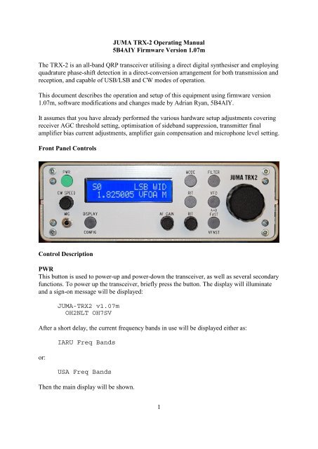
Front Panel Controls<br />
Control Description<br />
PWR<br />
This button is used to power-up and power-down the transceiver, as well as several secondary<br />
functions. To power up the transceiver, briefly press the button. The display will illuminate<br />
and a sign-on message will be displayed:<br />
<strong>JUMA</strong>-<strong>TRX</strong>2 v1.07m<br />
OH2NLT OH7SV<br />
After a short delay, the current frequency bands in use will be displayed either as:<br />
or:<br />
IARU Freq Bands<br />
USA Freq Bands<br />
Then the main display will be shown.<br />
1
To power down the transceiver, press and hold the power button, and a message will be<br />
displayed showing a count-down to zero. At this point the display will clear, the backlighting<br />
will be turned off, and the button can be released.<br />
During the count down period the current user settings are being written to the EEPROM. If<br />
the button is released during the count-down, it will be aborted, and the previous operation<br />
will be resumed.<br />
During normal operation, a brief press of the power button will toggle locking the VFO<br />
frequency. Note that this simply disables the VFO tuning knob, the receiver frequency can<br />
still be changed by pressing either the VFO button or using the Rapid Band Switch feature.<br />
The power button is also used to acknowledge and cancel any alarms. If an alarm cannot be<br />
cancelled, then press and hold the power button for 500 mSec and you will enter the<br />
emergency shutdown mode. Release the button and the transceiver will immediately shut off.<br />
In this mode it will bypass saving the user settings in favour of a rapid power down. For full<br />
details of the alarms, please refer to Annex F.<br />
If the power button is pressed and held whilst powering up, the system setup menu will be<br />
selected. The various operations and settings are fully covered in the System Setup section of<br />
this document. To exit the setup menu without making any changes, press and hold the power<br />
button to power the transceiver down.<br />
CW Speed<br />
This knob controls the speed of the internal keyer, or, can be used as a receiver squelch<br />
setting. The operation of this knob is controlled by a setting in the User Con<strong>fi</strong>guration menu,<br />
which is covered in the User Con<strong>fi</strong>guration section of this document.<br />
MIC<br />
The microphone/PTT switch is connected to this socket by means of a 3.5mm stereo jack.<br />
The wiring is:<br />
Tip<br />
Ring<br />
Screen<br />
: Microphone/Line input<br />
: PTT switch<br />
: Ground/Shield<br />
The PTT switch requires a dry contact closure to ground, or an open-collector connection<br />
capable of sinking 0.5mA from +5V.<br />
The microphone is normally expected to be an electret, and there is a bias voltage of +5V via<br />
a source resistance of 5.7K. If a dynamic microphone is used, a DC blocking capacitor should<br />
be wired in series with the tip connection. Most dynamic microphones have an impedance of<br />
about 400Ω, for optimum speech quality and low frequency response, a capacitor of at least<br />
2µF should be used. If using an electrolytic capacitor, wire the +ve to the tip of the plug.<br />
2
DISPLAY/CONFIG<br />
This multi-function button is normally used to control the transceiver’s display. In the receive<br />
mode the normal display has the S-meter, either as a numeric or graphic indication at the top<br />
left of the screen, followed by the mode indicator, (LSB/USB/CW/Tune), and the receiver’s<br />
<strong>fi</strong>lter, Wide (WID), Medium (MID), or Narrow (NAR).<br />
A brief push of the DISPLAY/CONFIG button will over-write the mode and bandwidth with<br />
the PWR display, which is only active during either transmit or tune operations. The next<br />
brief push will display the SWR, again only active during transmit or tune. The third push<br />
will show the current DC input voltage, the next push the transmitter’s <strong>fi</strong>nal ampli<strong>fi</strong>er’s drain<br />
current, also only active in transmit, and <strong>fi</strong>nally back to the normal display.<br />
If the button is pressed and held, after a short delay you will be presented with the User<br />
Con<strong>fi</strong>guration menu. This is more fully covered in the User Con<strong>fi</strong>guration section. To exit<br />
from this menu, press and hold the button until a long beep is heard, then release.<br />
AF GAIN<br />
This is the normal volume control.<br />
MODE<br />
This multi-function button has four functions:<br />
Mode Selection<br />
The primary function is that of selecting the operating mode. A brief push will select in turn<br />
LSB, USB, CW, or the Tune function.<br />
Memory Copy<br />
This function allows you to copy the contents of any active VFO to the User VFO Memory<br />
bank.<br />
Copy VFO-A to VFO-P<br />
To access this function, press and hold the MODE button until you hear a long beep. The<br />
display will alter as shown above. To copy from the active VFO to a memory, rotate the VFO<br />
knob clockwise, the direction arrow will point right, and the right-hand VFO memory<br />
designator will increment. In the example above, the active VFO is A, whose frequency and<br />
mode is displayed on the lower line, and is being copied to VFO memory P.<br />
Copy VFO memory J to active VFOA<br />
3
To copy from a VFO memory to the active VFO, turn the VFO knob anti-clockwise, and the<br />
source will decrement until you get to VFOA. The direction arrow will reverse showing that<br />
the direction of the transfer is from the VFO memory to an active VFO. In the example<br />
above, VFO memory J, whose frequency and mode are displayed on the lower line, is being<br />
copied to the active VFO, A.<br />
When the MODE button is released, the copy operation will be completed.<br />
Fast User Con<strong>fi</strong>guration Page Select<br />
As there are now 21 con<strong>fi</strong>guration pages, this feature allows you to rapidly select the desired<br />
con<strong>fi</strong>guration page. For details, see the User Setting Con<strong>fi</strong>guration section.<br />
Reset Defaults<br />
If this button is held and then the transceiver powered up, the system defaults can be restored<br />
without the necessity of using the System Setup facility. With the transceiver off, press and<br />
hold the MODE button, and briefly press the power button. Wait until the screen displays the<br />
message asking whether you wish to restore the factory defaults. Release the MODE button.<br />
A momentary push of the MODE button will restore the defaults, a momentary push of the<br />
FILTER button will abort the selection, and return you to normal operation.<br />
RIT<br />
A brief push of this button will toggle the Receiver Incremental Tune On/Off. When on, the<br />
lower right-hand portion of the screen will display the current offset frequency up to a<br />
maximum of ±1kHz, controlled by the RIT knob.<br />
If the Include RIT feature is enabled in the User Setup, then the frequency display will show<br />
the actual receiver frequency including the RIT shift.<br />
Frequency Display Including RIT Offset<br />
A long push of this button will invoke the Rapid Band Selection feature.<br />
Rapid Band Select In Use<br />
4
If this is invoked, the top line of the display will show the band to be selected, from 160 – 10<br />
metres. If the current receiver’s frequency is within an amateur band, then the selection will<br />
display this band, and the lower frequency display will show the selected frequency. If the<br />
frequency is not within a recognised amateur band, then the out-of-band indicator will show<br />
on the main display, and the 160m band’s frequency will be shown, as illustrated above.<br />
The frequency displayed can be either a default band-centre, or a user stored frequency. These<br />
user frequencies are in addition to those stored in the 26 VFO memories that are also<br />
available, but whereas the VFO memories can store any frequency, the user frequencies can<br />
only be valid amateur band frequencies relative to the current frequency band setting<br />
corresponding to either IARU Region 1, or the US bands.<br />
To select an amateur band, simply rotate the VFO tuning knob which will cycle you through<br />
all the available bands from 160 through 10 metres. When the RIT button is released, the<br />
selected frequency will be used along with the mode stored.<br />
Note that this rapid band switching facility is disabled in both the Split mode of operation and<br />
if the transmitter is keyed either with the PTT switch or a key. It is also inoperative in the<br />
Service and User Con<strong>fi</strong>guration modes.<br />
To save a favourite amateur band frequency, please refer to the FILTER button operation.<br />
FAST/VFAST<br />
This button is used to select the various tuning rates that are available. A brief press will cycle<br />
through the Slow (S) Medium (M) and Fast (F) tuning rates, corresponding to tuning rates of<br />
1Hz, 10Hz, and 100Hz.<br />
A long push will select the Very Fast (V) tuning rate of 10kHz. To exit the Very Fast mode,<br />
briefly press the button, and the default Medium 10Hz tuning rate will be selected.<br />
VFO/A=B<br />
This button selects which VFO will be used, as well as several secondary VFO related<br />
functions.<br />
If the operating mode is set to A/B + Split in the User Con<strong>fi</strong>guration setup, then a brief<br />
push of the button will cycle through the VFO-A, VFO-B, and Split modes. In the Split mode<br />
the receive frequency and mode is stored in VFO-A, and the transmit frequency and mode in<br />
VFO-B.<br />
In the Split mode, the rapid band switch and user frequency select/store operations are<br />
inhibited. It is highly inadvisable to change frequencies in this mode for obvious reasons. In<br />
order to do so, select either VFO-A or VFO-B.<br />
To copy the VFO-A frequency to VFO-B, select VFO A, and press and hold the VFO button<br />
until you hear a long beep, and the display will show:<br />
5
Split Mode Copy, VFOA to VFOB<br />
To copy the VFO-B frequency to VFO-A, <strong>fi</strong>rst select VFO-B, and press and hold the button,<br />
and a similar display will be shown except that the source will be VFOB, and the destination<br />
will be VFOA.<br />
If the button is pressed and held whilst the Splt is displayed, this is the same as VFO-A to<br />
VFO-B.<br />
If the User Con<strong>fi</strong>guration setting is for from 3 to 26 memories, then these can be selected<br />
sequentially by a brief press of the button, or if the button is held, they can be selected by<br />
rotating the VFO tuning knob. The last frequency/mode used for the selected VFO will be set.<br />
Any frequency in the range 0 – 30MHz can be stored in the 26 VFO memories.<br />
FILTER<br />
This button is primarily used to select the receiver bandwidths, but also has a secondary<br />
function of storing user frequencies.<br />
A brief press of the button will cycle you through the Wide, Medium, and Narrow <strong>fi</strong>lter<br />
bandwidths. The actual bandwidths employed are adjustable via the User Con<strong>fi</strong>guration<br />
Menu.<br />
A long press of the button will store the currently displayed frequency and mode into the user<br />
band memory. There are 9 such memories, one for each amateur band, and they are selected<br />
by the Rapid Band Switch feature assigned as a secondary function of the RIT button.<br />
To use this feature, the User Con<strong>fi</strong>guration Band Switch setting has to be set to the User<br />
mode. In this mode, the current frequency can be stored. Note, only frequencies within a<br />
recognised amateur band can be stored. If an attempt is made to store an invalid frequency the<br />
top line of the display will show:<br />
Out Of Band!<br />
Saving A Frequency To A User Band<br />
6
Similarly, if the Band Switch setting is in the Default mode, then the display will show:<br />
Not In User Mode<br />
If the Band Switch setting is in the Locked mode, then the display will show:<br />
User Mem Locked!<br />
A successful storage operation will display the message:<br />
Saved to:<br />
nnn<br />
where nnn will be replaced by a band from 160 – 10.<br />
In this manner it is possible for the user to preset favourite frequencies for each amateur band,<br />
and to retrieve them on demand. By selecting the Locked mode, these frequencies can be<br />
protected.<br />
System Calibration & Setup<br />
It is assumed that the initial adjustments and settings have been made.<br />
To enter the System Calibration & Setup menu, turn the transceiver off, and then press and<br />
hold the power button until the message:<br />
<strong>JUMA</strong>-<strong>TRX</strong>2 v1.07m<br />
Service Mode<br />
is displayed. To cycle through the various setting screens, briefly press the DISPLAY button.<br />
Set Reference Oscillator Frequency<br />
Default: 180000000Hz<br />
The DDS is fed with the output of the precision crystal oscillator, and in the current models is<br />
a packaged component with an output frequency of nominally 30MHz. The worst-case<br />
tolerance for this oscillator is ±100ppm, which translates to a possible error of ±3kHz at<br />
30MHz, and since this oscillator’s frequency is internally multiplied by 6 in the DDS chip,<br />
this can be as high as ±18kHz at 180MHz.<br />
To correct this, the reference frequency can be set to the frequency resulting from a x6<br />
multiplication of the crystal oscillator’s actual output frequency.<br />
In order to determine the necessary calibration factor, an accurate frequency counter is<br />
essential. If you have access to a counter which has an accuracy of better than at least ±1ppm,<br />
then measure the output frequency of the oscillator using the 10 second timebase, making at<br />
least 10 measurements. Average the results to 2 decimal places and multiply by 6. Round this<br />
<strong>fi</strong>gure to 1Hz, and this is the frequency to which the reference oscillator should be adjusted.<br />
7
It is also possible to use a less accurate frequency counter if you can tune to a standard<br />
frequency transmission. These are usually maintained to an accuracy of better than 0.1ppm.<br />
For an example of how to use this method, please refer to Annex B.<br />
The range of the input setting is checked, and there is an adjustment range of ±20kHz.<br />
Anything outside of this <strong>fi</strong>gure is cause for extreme suspicion regarding the crystal oscillator.<br />
Even adjustment settings of more than ±10kHz would warrant further investigation as the<br />
vast majority of these oscillators have a basic frequency accuracy at room temperature of well<br />
within the stated worst-case <strong>fi</strong>gure.<br />
Supply Voltage Calibration Factor<br />
Default: 5300<br />
The microprocessor chip uses an internal 12-bit A-D convertor, and this in turn is referenced<br />
to the +5V logic supply. Assuming that the regulator chip is exactly at +5V, this gives an<br />
incremental digital step size 5mV. This is the basic resolution of the digital meter. Use an<br />
accurate digital multimeter and measure the supply voltage at the transceiver’s input, and<br />
adjust the calibration factor to achieve a display as close as possible to that measured.<br />
The accuracy of the internal measurement system has been enhanced with this version of the<br />
<strong>fi</strong>rmware, and the incremental quantisation steps are now such that it should be possible to set<br />
the voltmeter to exactly match your measured value<br />
The range is checked, and values from 4000 – 6000 are acceptable, although values<br />
signi<strong>fi</strong>cantly different (more than ±250) from the default value suggest that the logic voltage<br />
should be checked, and investigated.<br />
RF Ampli<strong>fi</strong>er Drain Current<br />
Default: 2400<br />
Using an accurate ammeter, measure the current drawn by the ampli<strong>fi</strong>er when supplying 10W<br />
in the Tune mode to a dummy load. The value is usually in the range of approximately 2.0 to<br />
2.5A Note that the ammeter only measures the ampli<strong>fi</strong>er’s drain current. Using an accurate<br />
ammeter measure the current drawn in the receive mode, and subtract this value from the total<br />
current drawn in the transmit mode. Adjust the calibration factor to achieve the closest match.<br />
The default value is usually satisfactory. The limits are from 1200 – 3600.<br />
Forward Power Calibration Factor<br />
Default: 3550<br />
Using a dummy load, and an accurate power meter, set the transmitter’s output in the Tune<br />
mode using the CARR control on the main board to a forward power of 10W. Adjust the<br />
calibration factor to achieve the closest match. The limits are from 1500 – 5000.<br />
S-Meter Calibration Factor<br />
Default: 1920<br />
This adjusts the accuracy of the S-Meter display, and requires careful consideration. Early<br />
transceivers had a JFET type SST112 used for the AGC ampli<strong>fi</strong>er in position TR4 of the<br />
variable gain ampli<strong>fi</strong>er A4-B on the main board. Later transceivers had a substitute device<br />
8
type PMBFJ112, and the threshold voltage of this transistor differs from that of the SST112.<br />
This leads to a signi<strong>fi</strong>cant difference in the two calibration settings.<br />
In both cases, the adjustment procedure involves terminating the receiver in a 50Ω dummy<br />
load, rotating R53 fully anticlockwise to achieve maximum gain, and then carefully rotating<br />
clockwise until the audio noise just starts to decrease. This is the AGC threshold.<br />
Using a signal generator inject an S9+40dB signal, 5mV, 33dBm, and adjusting the<br />
calibration factor until either the numeric S-Meter just indicates S9+40dB, or the graphical S-<br />
Meter just <strong>fi</strong>lls the horizontal display. Then lower the signal to S9, 50µV, 73dBm and by a<br />
combination of R53 and the calibration factor adjustments try and achieve the best<br />
compromise between full-scale and S9 for the two signal levels.<br />
Since the threshold voltage of the two transistors is signi<strong>fi</strong>cantly different, early transceivers<br />
are likely to have calibration factors close to the default, whilst later units will be in the range<br />
of about 3,500 – 4,000. The limits are from 1,000 – 7,000.<br />
Beep Time<br />
Default: 50mS<br />
This adjustment determines the time of all the audio annunciator signals. Adjust the value to<br />
your preference. The range is checked, and values from 0 – 100mS are allowed. If the value is<br />
set to 0, no audible annunciation will occur.<br />
High SWR Trip Limit<br />
Default: 3.00<br />
This is a new feature as part of the alarm sub-system. If the SWR exceeds the trip limit, an<br />
alarm will be generated and displayed on the main screen. The limit can be set from 1.00 –<br />
5.00. Although a setting of 1.00 may seem odd, it allows you to check that the alarm is<br />
working. Set the limit to 1.00, and exit from the System Calibration menu by saving the<br />
settings.<br />
Connect the transceiver to a dummy load, select Tune, and press the PTT switch. If the alarm<br />
is working, then you should see a blinking message “HIGH SWR” on the top line of the display,<br />
along with a beep. To cancel the alarm, release the PTT switch, and briefly press the PWR<br />
button.<br />
Switch off, and reselect the System Calibration menu again, and reset the SWR Trip to a<br />
suitable value.<br />
Overcurrent Trip<br />
Default: ON<br />
This allows you to enable or disable this alarm. If the alarm is disabled, then the following<br />
page will be skipped, although its settings will be retained, and can be adjusted if the alarm is<br />
enabled.<br />
9
Overcurrent Trip (Adjustment)<br />
Default: 2.5A<br />
This is a new feature. Adjust the limit to a suitable value. The default is usually satisfactory.<br />
The value can be set from 1.5A – 3.0A. Temporarily setting the trip to 1.5A allows you to<br />
verify that it is working.<br />
As with the SWR test, save the calibration settings, using a dummy load and the Tune mode,<br />
press the PTT switch. The top line of the display will show the blinking message<br />
“OVERCURRENT”, there will be a beep. Release the PTT switch and briefly press the PWR<br />
button to cancel the alarm. Switch off and reselect the System Calibration menu and reset the<br />
trip to a suitable value.<br />
Note that the current measured is that of the <strong>fi</strong>nal ampli<strong>fi</strong>er. The internal fuse is rated at 3.5A,<br />
and since the transceiver’s logic and display sections can consume up to 400mA, the normal<br />
trip limit of 2.5A represents a conservative safety margin. Under some circumstances,<br />
especially if you are attempting to obtain the maximum power out of the transceiver, then it<br />
may be necessary to set the limit to the maximum permissible, 3.0A. Be aware however that<br />
with the logic and backlighting current as well, this is running very close to the fuse rating.<br />
Overvoltage Trip<br />
Default: ON<br />
This allows you to enable or disable this alarm. If the alarm is disabled, then the following<br />
page will be skipped, although its settings will be retained, and can be adjusted if the alarm is<br />
enabled.<br />
Overvoltage Trip (Adjust)<br />
Default: 14.5V<br />
This is a new feature. Adjust the limit to your preference. The range is from 14.0V – 15.0V.<br />
Undervoltage Trip<br />
Default: ON<br />
This allows you to enable or disable this alarm. If the alarm is disabled, then the following<br />
page will be skipped, although its settings will be retained, and can be adjusted if the alarm is<br />
enabled.<br />
Undervoltage Trip (Adjust)<br />
Default: 11.0V<br />
This is a new feature. Whilst the transceiver will continue to operate down to quite low<br />
voltages, when operating portable from Gell cells most manufacturers recommend<br />
terminating the discharge when the terminal voltage falls to 10.5V.<br />
The transceiver can be set to warn you with a blinking “UNDERVOLTAGE” display and a beep at<br />
any voltage from 10.50V – 11.50V. Note, in addition to this <strong>fi</strong>nal warning, there is a pre-limit<br />
warning which occurs at a voltage 100mV higher than this setting. This will display the<br />
blinking alarm message: “Low Batt Voltage”, and beep.<br />
10
Acknowledge and cancel the warning by briefly pressing the PWR button. This warning will<br />
only be given once – it will NOT repeat! Once you have acknowledged the warning it<br />
disappears. The only way to reset it is to power the transceiver off and back on again.<br />
The next screen displays the message:<br />
Push FAST long =<br />
factory defaults<br />
Only in this screen can you reset the transceiver to these default values. Push and hold the<br />
FAST button until you hear a long beep, and the values will have been reset.<br />
Otherwise, press the DISPLAY button briefly to return you to the initial screen, and briefly<br />
press the FAST button to save the current values.<br />
To abort the whole process, press and hold the PWR button to turn the transceiver off.<br />
User Con<strong>fi</strong>guration Settings<br />
To enter the User Con<strong>fi</strong>guration settings, press and hold the DISPLAY button until you hear a<br />
long beep.<br />
With version 1.07, there are now 21 settings that can be adjusted to your preferences. With<br />
this many con<strong>fi</strong>gurable settings there is now an additional feature allowing you to rapidly<br />
access any con<strong>fi</strong>guration page.<br />
To use this feature, press and hold the MODE button until you hear a long beep. Rotate the<br />
VFO knob to select the desired con<strong>fi</strong>guration page. To adjust the setting, release the MODE<br />
button, and use the VFO knob to adjust the current setting.<br />
AGC Speed<br />
Default: Slow<br />
Use the tuning knob to select either Fast or Slow AGC action.<br />
Low-Pass Filter Cut-Off Frequencies<br />
Default: Wide – 2,500Hz, Mid – 2,205Hz Narrow – 1,000Hz<br />
Use the FILTER button to select the <strong>fi</strong>lter whose cut-off frequency you wish to adjust. Use<br />
the tuning knob to select the desired cut-off frequency. Note that the frequency resolution is<br />
relatively coarse due to the methods used to clock the SCAF <strong>fi</strong>lter, but this is of little<br />
consequence, since precise cut-off frequencies are not required.<br />
Noise Blanker Option<br />
Default: OFF<br />
This is set to ON/OFF with the tuning knob. If no accessory board is installed, it should be set<br />
to OFF.<br />
11
Speech Processor<br />
Default: OFF<br />
The transceiver is equipped with a simple speech processor which uses a soft-clipping<br />
method to achieve a higher peak to average ratio for speech to increase the average talkpower.<br />
However, this also leads to a certain amount of distortion, and thus this setting has to be<br />
carefully related to the transmit SSB gain setting, R26. Too little gain, and no compression<br />
will occur, too high a gain, and excessive distortion will occur. Turn the Speech Processor on,<br />
and listen on another receiver when operating into a dummy load to determine the optimum<br />
gain setting.<br />
Audio Input Source<br />
Default: Mic<br />
Use the tuning knob to select microphone or line. When set to line, the gain is reduced by<br />
about 30dB. This allows the connection of the transceiver to the output of a computer’s audio<br />
system for digital mode operation.<br />
Note however that to satisfactorily use digital modes the speech processor must be turned off,<br />
and the transceiver’s microphone ampli<strong>fi</strong>er circuit slightly modi<strong>fi</strong>ed to completely disable the<br />
speech processor in the off mode.<br />
Keyer Mode Selection<br />
Default: Iambic B<br />
Select Iambic A, Iambic B, Dot Priority, or Straight key operation.<br />
CW Pitch<br />
Default: 700Hz<br />
Use the tuning knob to select the desired pitch for CW signals. The range is checked and<br />
values from 300Hz – 1,100Hz are acceptable. This is also the offset used when transmitting.<br />
The actual transmit frequency is lower than the receive carrier by this amount.<br />
CW Pot Mode<br />
Deafult: CW Speed<br />
The CW pot can be used either as a keyer speed setting or a receiver squelch control. Use the<br />
tuning knob to select the desired function.<br />
LCD Backlight<br />
Default: 350<br />
The intensity of the LCD display can be adjusted with this setting. Values from 0 – 1,100 are<br />
accepted.<br />
LCD Contrast<br />
Default: 2000<br />
This setting adjusts the display contrast. The default of 2,000 is usually acceptable. The range<br />
of values accepted is from 0 – 3,500.<br />
12
LCD Timer<br />
Default: OFF<br />
The display can be automatically turned off after a preset time using this feature. Adjust the<br />
timer to a value between OFF and 3,600 seconds.<br />
RS-232<br />
Default: Yaesu CAT<br />
This setting governs a number of peripheral features. It can be set to the following modes:<br />
<strong>JUMA</strong> <strong>TRX</strong>2<br />
This mode is used to enable serial communication with the companion <strong>JUMA</strong> PA100D<br />
100W linear ampli<strong>fi</strong>er.<br />
Yaesu CAT<br />
This allows communication with PC logging programs, and emulates a Yaesu transceiver. For<br />
a list of commands that are emulated, please see Annex C.<br />
Kenwood CAT<br />
This allows communication with PC logging programs, and emulates a Kenwood TS-480<br />
transceiver. For a list of commands that are emulated, please see Annex D.<br />
Voice Memory<br />
This mode is used with the accessory voice memory board.<br />
Test<br />
This mode is used to verify the integrity of the transceiver’s internal circuitry and software, as<br />
well as check that the serial communications port is working correctly. In this version of the<br />
<strong>fi</strong>rmware several serial port bugs were corrected, and a user help feature added which briefly<br />
describes the operation of each command.<br />
Connect the transceiver to a PC, use a suitable terminal program, ensure that the speed<br />
settings are correct. Send the letter I, , H, or h from the PC and the transceiver should<br />
respond with a screen of information. The actual usage of these commands in beyond the<br />
scope of this document, and in any case is only likely to be of interest to those wishing to<br />
customise the software.<br />
Note that these commands are not in any way destructive – they cannot permanently affect the<br />
overall operation of the transceiver. For a brief description please see Annex E.<br />
Baud Rate<br />
Default: 9600<br />
This allows setting the speed of the serial port from 1,200 – 115,200 Baud. The default of<br />
9,600 is usually satisfactory.<br />
13
VFO Memory Operation<br />
Default: A/B + Split<br />
This setting governs how the various VFO memories are used and organised. The settings<br />
range from A/B + Split mode, to 3 – 26 memories.<br />
Split mode operation involves transmitting on one frequency, and receiving on another. The<br />
frequencies can be anywhere in the tuning range of the transceiver. VFO A is used for the<br />
receive frequency; VFO B for transmit.<br />
When not using Split mode, you can select the number of VFO memories available to you<br />
from 3 – 26, which will be indicated on the display by the letters VFOA – VFOZ. The current<br />
displayed frequency and mode is automatically stored in the selected VFO.<br />
These VFOs can be selected by a brief press of the VFO button, or the VFO button can be<br />
held down and the memories selected by the tuning knob.<br />
S-Meter<br />
Default: Graphic<br />
This new feature allows you to select either a graphical S-Meter (Original) or a numeric S-<br />
Meter. The gain characteristics of a correctly adjusted and calibrated receiver are almost<br />
exactly logarithmic over the dynamic range of the receiver, which lends itself to an easy<br />
implementation of either display with reasonable accuracy. Use the tuning knob to select<br />
either type of display.<br />
TX Disable<br />
Default: ON<br />
This is a new feature. The original <strong>fi</strong>rmware allowed transmission on any frequency,<br />
including those outside the amateur bands. This meant one had to pay careful attention when<br />
operating close to the band edges in order to avoid an infraction of your licence conditions.<br />
By enabling this feature, if you attempt to transmit in any mode on a frequency outside the<br />
recognised band, the transmitter is inhibited, and the display will show a message:<br />
Out Of Band!<br />
In addition, in the receive mode, there is a small annunciator displayed immediately between<br />
the frequency display and the VFO selection/mode section of the lower line of the screen if<br />
the current receive frequency is outside the amateur bands.<br />
Transmit Inhibit<br />
14
Even if this feature is turned off, the receive annunciator is still displayed, and storage of a<br />
frequency in the User Band memory is inhibited.<br />
Auto Sideband Select<br />
Default: ON<br />
This is a new feature. Conventionally, for frequencies above 10MHz USB is the preferred<br />
mode for voice communication, conversely, LSB for frequencies lower than 10MHz. This<br />
feature will automatically select the correct sideband when tuning to an amateur band using<br />
the Rapid Bandswitch Feature. It does not affect tuning when using the tuning knob. Even<br />
with auto sideband selected, you may still choose any operating mode on any band.<br />
Frequency Display Selection<br />
Default: Fixed B<br />
This is a new feature. The original frequency display was limited to 10Hz resolution, and<br />
used two decimal points, between the MHz and 100kHz digits and between the kHz and<br />
100Hz digits. This feature now permits a variety of display options.<br />
Original<br />
The frequency will be displayed as:<br />
Original Frequency Display<br />
New<br />
The frequency will be displayed depending upon the tuning rate being used, thus:<br />
Slow Tuning Rate – 1Hz<br />
Medium Tuning Rate – 10Hz<br />
15
Fast Tuning Rate – 100Hz<br />
Very Fast Tuning Rate – 10kHz<br />
Note that the precision is not affected, the display is merely rounded to the appropriate tuning<br />
rate’s resolution, but selecting a higher resolution tuning rate will reveal the rounded digits.<br />
With version 1.07g and later, the accuracy of the synthesiser has been improved. See<br />
Annex A for a full explanation.<br />
Fixed A<br />
The display is <strong>fi</strong>xed at 1Hz resolution independent of the tuning rate used. For frequencies<br />
below 1MHz the decimal point will move to the kHz position, and no leading zeros are used.<br />
(See note 6 at the end of this document.)<br />
Fixed Resolution – 1Hz<br />
Fixed B<br />
The display is <strong>fi</strong>xed at 10Hz resolution, independent of the tuning rate used.<br />
Fixed Resolution – 10Hz<br />
16
Band S/W<br />
Default: Default<br />
This is a new feature. This setting governs how the Rapid Bandswitch feature operates.<br />
Default<br />
In this mode, when selecting an amateur band, the frequency used will be <strong>fi</strong>xed at the band’s<br />
centre.<br />
BAND<br />
FREQUENCY MHz<br />
160 metres 1.900<br />
80 metres 3.650<br />
40 metres 7.100<br />
30 metres 10.125<br />
20 metres 14.175<br />
17 metres 18.118<br />
15 metres 21.225<br />
12 metres 24.940<br />
10 metres 28.850<br />
User<br />
In this mode, initially when the <strong>fi</strong>rmware is <strong>fi</strong>rst loaded the frequencies are set to match the<br />
default settings. However, the user can store new frequencies as desired, provided that they<br />
are within the amateur band in question. The upper and lower frequencies to be used as the<br />
band edges are determined by the setting of the Band Limits parameter in a following menu.<br />
The out-of-band indication is dependent upon the mode in use. For USB, the carrier<br />
frequency has the transmit <strong>fi</strong>lter bandwidth of 2.6kHz added to ensure that the entire upper<br />
sideband falls within the upper band edge, no correction is applied to the lower band edge.<br />
For LSB, the frequency has the transmit <strong>fi</strong>lter bandwidth subtracted to ensure that the entire<br />
lower sideband falls within the lower band edge. Similarly for CW, where in this case the CW<br />
Pitch is used.<br />
For the Tune mode, no corrections are applied, as the carrier frequency itself is used.<br />
Locked<br />
This mode uses the currently preset User frequencies, but the memory is locked so that no<br />
alteration can occur.<br />
17
Include RIT<br />
Default: NO<br />
This is a new feature. If this is turned on, then the RIT offset frequency will be used to modify<br />
the frequency displayed to show the actual receive frequency.<br />
Band Limits<br />
Default: IARU<br />
This is a new feature. The transceiver’s band edge frequencies can be set to either the IARU<br />
Region 1 limits, or the USA limits. When altering this setting note that it will take effect<br />
when the transceiver is next powered up.<br />
Minor Enhancements<br />
1. The RIT, VFO, and FAST/VFAST buttons are locked out when in the User Setup<br />
mode. The MODE button is used to rapidly access the con<strong>fi</strong>guration pages. Note that<br />
although the MODE button is active in the User Setup mode, no mode changes will<br />
occur, that is, the existing mode (LSB/USB/CW/Tune) will not be disturbed.<br />
2. The MODE, FILTER, RIT, VFO, and FAST/VFAST buttons are locked out when in<br />
the transmit mode.<br />
3. The power-down sequence timing is no longer critical. In the previous software, one<br />
had to time the release of the power button fairly accurately to avoid either aborting<br />
the sequence or powering the transceiver back up. In this version, as soon as the<br />
display blanks you can release the button, holding it down will no longer cause a<br />
power-up to occur.<br />
4. Various audio glitches when changing frequencies or modes have been eliminated or<br />
greatly suppressed, although there are still a few stubborn candidates left. Work in<br />
progress.<br />
5. The lowest frequency to which the transceiver can be tuned is 0Hz. Whilst the<br />
frequencies below about 30kHz have no real importance, the very low frequency<br />
output at audio frequencies does allow the user to verify that the DDS chip is<br />
operating. By tuning down into the audio range you will hear an audio beat note which<br />
can be measured with a frequency counter to provide an approximate indication that<br />
the frequency synthesis is correct.<br />
6. Version 1.07h and later slightly modi<strong>fi</strong>ed the way that the Fixed-A display operates.<br />
After careful consideration, I decided that displaying frequencies below 1MHz with<br />
leading zeros was simply ugly. The display now shows a decimal point at the MHz<br />
position for frequencies above 999.999kHz, and simply moves the decimal point to<br />
the kHz position and <strong>fi</strong>lls the leading spaces with blanks for frequencies from 1kHz to<br />
999.999kHz. For frequencies below 1kHz, no decimal point is displayed.<br />
7. The spurious power-down count when locking or unlocking the VFO has been<br />
cleared.<br />
18
8. The <strong>fi</strong>lter change points for the 2MHz and 4MHz <strong>fi</strong>lters have been moved up by<br />
10kHz. It was particularly disconcerting that right at the 2.0MHz and 4.0MHz<br />
frequencies these <strong>fi</strong>lters would be changed. The new frequencies are 2.010MHz, and<br />
4.010MHz.<br />
9. The Serial Test facility has been enhanced with the addition of a dump of the<br />
attenuator settings corresponding to the various internal <strong>fi</strong>lters.<br />
10. Various minor internal code optimisations.<br />
Adrian Ryan – <strong>5B4AIY</strong><br />
12 October 2011<br />
19
Annex A<br />
<strong>JUMA</strong> Frequency Step Accuracy<br />
The Juma <strong>TRX</strong>2 using <strong>fi</strong>rmware revision 1.06 has an inherent frequency resolution of 10Hz.<br />
This means that the actual frequency to which the transceiver is tuned is within ±5Hz of the<br />
displayed frequency, if we neglect the reference oscillator errors. Or is it<br />
If we carefully examine the frequency display, we can observe some interesting quirks. Try<br />
this, tune the transceiver to, say, 10.00000Mhz, and select the fast tuning rate of 100Hz, now<br />
rapidly rotate the VFO knob to increase the frequency and carefully observe the least<br />
signi<strong>fi</strong>cant (10Hz) digit. After a large number of steps the digit will suddenly change by 1.<br />
Select the slow (10Hz) tuning rate and carefully go back and <strong>fi</strong>nd the exact frequency at<br />
which the 10Hz digit changed, and note it. As an example, in my case it was 10.20840MHz.<br />
Now re-select the fast tuning rate and increase the frequency, and in my case at 10.46510 the<br />
10Hz digit changed again and with a single increment from the tuning knob the display<br />
changed from 10.46510 to 10.46519, and the next increment was to 10.46529.<br />
The reason for this anomaly is not hard to <strong>fi</strong>nd. The output frequency of the synthesiser is:<br />
f local oscillator = N * 180000000 / 2^33 Hz<br />
Where N is the 32-bit binary word used to load the DDS chip. In fact, the actual output<br />
frequency is twice this, but the synthesiser’s frequency is divided by two to obtain the phasequadrature<br />
local oscillator signal.<br />
The frequency steps are obtained from an array of steps and for a step increment of 100Hz the<br />
value is 4,772. This is the binary increment that is added to the existing frequency word for<br />
every step generated by the VFO encoder at the 100Hz tuning rate.<br />
The actual frequency increment is therefore:<br />
f increment = 4772 * 180000000 / 8589934592<br />
= 99.996104837 Hz<br />
There is thus an incremental step error of 0.003895164 Hz for each step, and eventually<br />
these step errors accumulate until there is suf<strong>fi</strong>cient error for the next step to cause the 10Hz<br />
digit to change.<br />
In fact, after every 2,567 steps this anomaly will appear, corresponding to a frequency change<br />
of about 256Khz.<br />
Now, one could reasonably say, “So what” and I would entirely agree that for all practical<br />
purposes this is of no real signi<strong>fi</strong>cance, the actual frequency of the transceiver is always<br />
within ±5Hz of the displayed frequency, which is more than adequate – even on the lowest<br />
20
amateur band this represents a tuning accuracy of ±2.5ppm, and even better at the higher<br />
frequencies.<br />
But, I’m a perfectionist, you might even say obsessive, and it occurred to me that the<br />
synthesiser could do better. After all, when you increment the DDS word by 1 the local<br />
oscillator’s frequency changes by 0.020955 Hz, and thus there is the potential for the<br />
transceiver’s actual resolution accuracy to be improved by a factor of 250.<br />
The problem arises because all the frequency calculations are done in the DDS domain, and<br />
thus the approximation errors accumulate. If the calculations and increments are performed<br />
entirely in the decimal domain, then there are no display anomalies, and with the decimal<br />
frequency being converted only once to its DDS equivalent word, the worst error that can<br />
occur is a ±1 bit quantisation error leading to a worst-case resolution error of 0.04Hz allowing<br />
for rounding errors in the calculation.<br />
I have thus changed the complete frequency synthesis numerical base from DDS units to<br />
decimal, and modi<strong>fi</strong>ed the load_dds()function so that it is passed a decimal frequency and<br />
the conversion to the DDS word is performed once.<br />
As a result, and con<strong>fi</strong>rmed with an accurate frequency counter, the accumulating step errors<br />
are eliminated.<br />
<strong>Firmware</strong> versions from 1.07h on incorporate this change, as well as a number of other minor<br />
internal changes.<br />
By correcting for the production tolerances of the 30MHz oscillator, the transceiver can now<br />
achieve a frequency accuracy on a par with almost anything on the market – what a really nice<br />
little ‘gem’ this is!<br />
Adrian Ryan <strong>5B4AIY</strong><br />
21
Annex B<br />
Reference Oscillator Calibration<br />
The accuracy of the reference oscillator determines the overall frequency accuracy of the<br />
transceiver. The master oscillator is the 30MHz package oscillator on the DDS board, and its<br />
output is used both to clock the microprocessor, as well as provide the reference for the DDS<br />
synthesiser chip.<br />
The IQD IQX-350 series of packaged oscillators have a worst-case frequency tolerance of<br />
±100ppm over a temperature range of 0C – 70C. In fact, at room temperature, the actual<br />
output frequency is usually well within the worst-case speci<strong>fi</strong>cation. Nevertheless, your<br />
oscillator is unlikely to be at exactly 30MHz, and thus since this frequency is multiplied by 6<br />
in the DDS chip, the output frequency will have an offset error. By inserting the appropriate<br />
calibration frequency this offset can, to a large extent, be eliminated, thus greatly improving<br />
the accuracy of the frequency generating system.<br />
Method 1 – Direct Calibration<br />
The <strong>fi</strong>rst method of calibrating the system simply involves measuring the output frequency of<br />
the 30MHz oscillator directly using a stable, accurate frequency counter. The time-base of the<br />
counter has to be a precision reference, preferably locked to a rubidium standard, and<br />
certainly within ±1ppm.<br />
This is a fairly stringent speci<strong>fi</strong>cation to meet, and the average frequency counter from, for<br />
example, eBay is unlikely to meet this. It really requires access to a laboratory grade counter<br />
whose calibration is current.<br />
If you have access to such a counter, then carefully measure the output frequency to an<br />
accuracy of 1Hz using the 10 second time-base setting and collect at least 10 measurements.<br />
Average these to 2 decimal places. Multiply the result by 6 and round to 1Hz, and this is the<br />
reference oscillator calibration frequency to be inserted.<br />
Method 2 – Indirect Calibration<br />
This second method uses a combination of a transmitted standard frequency and a frequency<br />
counter of nominal accuracy. In this method the audio beat frequency will be used, and the<br />
accuracy of the frequency counter is less important. Even a counter whose time-base is in<br />
error by 100ppm will suf<strong>fi</strong>ce. If the time-base error is 100ppm, then at an audio frequency of<br />
1,000Hz, the actual reading will be between 999.9Hz and 1000.1Hz. Although this will lead<br />
to an uncertainty of about ±5Hz at 180MHz, this is still accurate enough.<br />
Tune the receiver to a standard frequency transmission, and set the display to be exactly<br />
1,000Hz higher than the carrier frequency. For example, suppose we use a transmitter on<br />
5MHz. Set the display to 5.001000 (Use the 1Hz tuning rate, and the 1Hz frequency display<br />
option, and lock the VFO.) Select LSB, and MID <strong>fi</strong>lter.<br />
22
Connect the frequency counter to the phone output socket, and adjust the audio gain for a<br />
suitable level to trigger the counter. In order to avoid excessive jitter the signal must be<br />
reasonably clean and reasonably free from noise.<br />
Set the frequency counter to display to 1Hz using the 10 second time-base. Make at least 10<br />
measurements, and average the results to 2 decimal places.<br />
If the reference oscillator were at its exact frequency, then the audio beat note would be<br />
exactly 1,000Hz. Any error will cause the frequency to be higher or lower than this. Subtract<br />
the 1,000Hz from the averaged result. Since the standard frequency in this example is 5MHz,<br />
to <strong>fi</strong>nd the error at 30MHz multiply the error by 30/5 and this is the frequency offset at<br />
30MHz. Add this to 30MHz and multiply by 6, and this is the reference oscillator calibration<br />
frequency. A numerical example should make this clear.<br />
Assume the standard frequency is 5MHz, and the receiver is tuned to 5.001000MHz, LSB.<br />
Measured Beat Frequency<br />
950<br />
949<br />
949<br />
950<br />
950<br />
948<br />
949<br />
949<br />
950<br />
950<br />
Averaging these results gives a beat frequency of: 949.40Hz<br />
Error: 949.40 1000 = 50.60Hz<br />
Crystal Oscillator Frequency = 30,000,000 + ((30,000,000 / 5,000,000) * 50.60)<br />
= 30,000,000 303.60 Hz<br />
= 29,999,696.40Hz<br />
23
Reference Oscillator Frequency = 29,999,696.40 * 6<br />
= 179,998,178Hz<br />
In this case, the crystal oscillator was low by about 10ppm.<br />
Now an example where the oscillator is high in frequency.<br />
For this example, assume the standard frequency is 10MHz. Tune the receiver to a display<br />
setting of: 10.001000MHz, LSB.<br />
Measured Beat Frequency<br />
1250<br />
1251<br />
1251<br />
1250<br />
1249<br />
1250<br />
1251<br />
1250<br />
1250<br />
1251<br />
Averaging these results gives a beat frequency of: 1250.00Hz<br />
Error: 1250.00 1000 = +250.00Hz<br />
Crystal Oscillator Frequency = 30,000,000 + ((30,000,000 / 10,000,000) * +250.00)<br />
= 30,000,000 + 750.00 Hz<br />
= 30,000,750.00Hz<br />
Reference Oscillator Frequency = 30,000,750.00 * 6<br />
= 180,004,500Hz<br />
In this case, the crystal oscillator was high by about 25ppm.<br />
24
Annex C<br />
Yaesu CAT Command Emulation<br />
If the RS-232 serial port mode is set to Yaesu CAT, then the transceiver will respond to the<br />
following command sequences:<br />
Yaesu Command Description<br />
Yaesu CAT commands are organised as a 5-byte sequence, with the parameters <strong>fi</strong>rst, and the<br />
last byte being the command byte.<br />
The following commands are emulated (values are in hexadecimal):<br />
Read RX frequency & mode : 03<br />
Read RX status<br />
: E7<br />
Read TX status<br />
: F7<br />
Split Mode ON : 02<br />
Split Mode OFF : 82<br />
VFO Select : 81<br />
Set operating mode : 07<br />
Set frequency : 01<br />
PTT ON (TX) : 08<br />
PTT OFF (RX) : 88<br />
Lock VFO : 00<br />
Unlock VFO : 80<br />
Command Format<br />
The commands take the form of a 5-byte string terminating with the command byte. The<br />
leading 4 bytes are the parameter values required. If a command does not require any<br />
parameters, then these bytes can contain any value, but nulls are preferred.<br />
Read RX Frequency and Mode<br />
Assume the transceiver’s frequency is 145.43210Mhz<br />
Command To Transceiver : 00 00 00 00 03<br />
Transceiver Response : 14 54 32 10 xx<br />
xx is the mode byte, with the following meaning: 00 = LSB, 01 = USB, 02 = CW<br />
There are a number of other values, but they are not applicable to the Juma <strong>TRX</strong>-2<br />
Read RX Status<br />
Command To Transceiver : 00 00 00 00 E7<br />
Transceiver Response : xx 00 00 00 00<br />
xx is the data byte, and the bits have the following meanings:<br />
25
7 Squelch Status 0 = OFF, Signal present, 1 = ON, Receiver squelched<br />
6 CTCSS/DCS code. For Juma = 0<br />
5 Discriminator Centering, for SSB/CW = 0<br />
4 Dummy Data 0<br />
3 S-Meter Bit 3<br />
2 S-Meter Bit 2<br />
1 S-Meter Bit 1<br />
0 S-Meter Bit 0<br />
The S-meter value is coded into 15 levels from S0 to S9+40dB<br />
Read RX Status<br />
Command To Transceiver : 00 00 00 00 F7<br />
Transceiver Response : xx 00 00 00 00<br />
xx is the data byte, and the bits have the following meanings:<br />
7 PTT Status 0 = TX, 1 = RX<br />
6 High SWR 0 = OFF, 1 = ON<br />
5 Split Mode 0 = ON, 1 = OFF<br />
4 Dummy Data 0<br />
3 PWR Meter Bit 3<br />
2 PWR Meter Bit 2<br />
1 PWR Meter Bit 1<br />
0 PWR Meter Bit 0<br />
The PWR-meter value is coded into 15 levels from 0 – 100W<br />
Split Mode ON<br />
Command To Transceiver : 00 00 00 00 02<br />
Split Mode OFF<br />
Command To Transceiver : 00 00 00 00 82<br />
VFO Select (Toggle VFO-A, VFO-B)<br />
Command To Transceiver : 00 00 00 00 81<br />
Set <strong>Operating</strong> Mode<br />
Command To Transceiver : xx 00 00 00 07<br />
Where xx has the following meanings: 00 = LSB, 01 = USB, 02 = CW<br />
Set <strong>Operating</strong> Frequency<br />
Command To Transceiver : aa bb cc dd 01<br />
Assume the frequency is: 14.23456MHz, aa = 01, bb = 42, cc = 34, dd = 56<br />
PTT ON (Transmit)<br />
Command To Transceiver : 00 00 00 00 08<br />
26
PTT OFF (Receive)<br />
Command To Transceiver : 00 00 00 00 88<br />
Lock VFO<br />
Command To Transceiver : 00 00 00 00 00<br />
Unlock VFO<br />
Command To Transceiver : 00 00 00 00 80<br />
27
Annex D<br />
Kenwood TS-480 CAT Command Emulation<br />
If the RS-232 serial port mode is set to Kenwood CAT, then the transceiver will respond to<br />
the following command sequences:<br />
Read/Set VFO-A Frequency : FA<br />
Read/Set VFO-B Frequency : FB<br />
Select/Read Receiver VFO : FR<br />
Select/Read Fine Tune<br />
: FS<br />
Select/Read Transmitter VFO : FT<br />
Read Transceiver Status<br />
: IF<br />
Set/Read CW Keyer Speed : KS (Not implemented)<br />
Read Current Mode<br />
: MD<br />
Set/Read Noise Blanker<br />
: NB<br />
Set/Read Speech Processor : PR<br />
Clear RIT Offset Frequency : RC (Not implemented)<br />
Move RIT Down : RD (Not implemented)<br />
Move RIT Up : RU (Not implemented)<br />
Set/Read RIT Function<br />
: RT<br />
Set/Read DSP Low Frequency : SL<br />
Set/Read DSP High Frequency : SH<br />
Read S-Meter Status<br />
: SM<br />
Set/Read Squelch Level : SQ (Not implemented)<br />
Turn TX ON<br />
: TX<br />
Turn RX ON<br />
: RX<br />
Read Transceiver Status<br />
: RS<br />
The command format is a two-letter ASCII command followed by a variable length parameter<br />
string of ASCII characters. The command is always terminated by the semi-colon (;)<br />
character. Note that a command can have zero parameters, in which case it is generally a data<br />
request.<br />
Set VFO-A Frequency<br />
Transmitted From PC (Assume the frequency is: 14.195MHz)<br />
FA00014195000;<br />
Read VFO-A Frequency<br />
Transmitted from PC<br />
FA;<br />
Response from TS-480 (Assume the frequency is: 14.195MHz)<br />
FA00014195000;<br />
Set VFO-B Frequency<br />
Transmitted From PC (Assume the frequency is: 14.195MHz)<br />
FB00014195000;<br />
28
Read VFO-B Frequency<br />
Transmitted from PC<br />
FB;<br />
Response from TS-480 (Assume the frequency is: 14.195MHz)<br />
FB00014195000;<br />
Select Receiver VFO<br />
Transmitted from PC<br />
FR0; Select VFO-A<br />
FR1; Select VFO-B<br />
Read Receiver VFO<br />
Transmitted from PC<br />
FR;<br />
Response from TS-480<br />
FR0; VFO-A selected<br />
FR1; VFO-B selected<br />
Select Fine Tune (1Hz)<br />
Transmitted from PC<br />
FS0; Fine Tune function OFF (Select 10Hz tuning rate)<br />
FS1; Fine Tune function ON (Select 1Hz tuning rate)<br />
Read Fine Tune<br />
Transmitted from PC<br />
FS;<br />
Response from TS-480<br />
FS0; Fine Tune function OFF (10Hz tuning rate)<br />
FS1; Fine Tune function ON (1Hz tuning rate)<br />
Select Transmitter VFO (See Split Mode Note)<br />
Transmitted from PC<br />
FT0; Select VFO-A<br />
FT1; Select VFO-B<br />
Read Transmitter VFO<br />
Transmitted from PC<br />
FT;<br />
Response from TS-480<br />
FT0; VFO-A selected<br />
FT1; VFO-B selected<br />
29
Read transceiver ID number<br />
Transmitted from PC<br />
ID;<br />
Response from TS-480<br />
ID020;<br />
Read Transceiver Status<br />
Transmitted from PC<br />
IF;<br />
Response from TS-480<br />
IFp1p1p1p1p1p1p1p1p1p1p1p2p2p2p2p2p3p3p3p3p3p4p5p6p7p7p8p9p10p11p12p13p14p1<br />
4p15;<br />
p1 : 11 digits of receiver frequency to 1Hz, example: 14.234567MHz = 00014234567<br />
p2 : 5 spaces<br />
p3 : RIT frequency ±nnnn Hz<br />
p4 : 0 = RIT Off, 1 = RIT On<br />
p5 : 0 = XIT Off, 1 XIT On (Not Applicable)<br />
p6 : 0 (Always 0)<br />
p7 : Memory Channel number 00 – 99 (Not Applicable)<br />
p8 : 0 = RX, 1 = TX<br />
p9 : 1 = LSB, 2 = USB, 3 = CW<br />
p10 : 0 = VFO A, 1 = VFO B<br />
p11 : 0 = Scan Off<br />
p12 : 0 = Simplex, 1 = Split<br />
p13 : 0 (Not Applicable)<br />
p14 : 00 (Not Applicable)<br />
p15 : space character<br />
; : End-Of-Command character<br />
Example 1: IF00014003920 0000000000020000080;<br />
RX Freq: 14.003920MHz RIT Freq: 0000, RIT Off, USB, VFO A, Scan Off, Simplex<br />
Example 2: IF00014003920 0123010000020000080;<br />
RX Freq: 14.003920MHz RIT Freq: +123, RIT On, USB, VFO A, Scan Off, Simplex<br />
Example 3: IF00014003920 -0123010000020000080;<br />
RX Freq: 14.003920MHz RIT Freq: -123, RIT On, USB, VFO A, Scan Off, Simplex<br />
Example 4: IF00014003920 0000000000020010080;<br />
RX Freq: 14.003920MHz RIT Freq: 0000, RIT Off, USB, VFO A, Scan Off, Split<br />
Set Mode<br />
Transmitted from PC<br />
MD1; LSB<br />
MD2; USB<br />
MD3; CW<br />
30
Read Current Mode<br />
Transmitted from PC<br />
MD;<br />
Response from TS-480 (Other modes are possible, but not applicable to a <strong>TRX</strong>-2)<br />
MD1; LSB<br />
MD2; USB<br />
MD3; CW<br />
Set Noise Blanker<br />
Transmitted from PC<br />
NB0; Noise Blanker OFF<br />
NB1; Noise Blanker ON<br />
Read Noise Blanker<br />
Transmitted from PC<br />
NB;<br />
Response from TS-480<br />
NB0; Noise Blanker OFF<br />
NB1; Noise Blanker ON<br />
Set Speech Processor<br />
Transmitted from PC<br />
PR0; Speech Processor OFF<br />
PR1; Speech processor ON<br />
Read Speech Processor<br />
Transmitted from PC<br />
PR;<br />
Response from TS-480<br />
PR0; Speech Processor OFF<br />
PR1; Speech processor ON<br />
Set RIT Function<br />
Transmitted from PC<br />
RT0; RIT OFF<br />
RT1; RIT ON<br />
Read RIT status<br />
Transmitted from PC<br />
RT;<br />
Response from TS-480<br />
RT0; RIT OFF<br />
RT1; RIT ON<br />
31
Set Low Frequency Filter DSP Settings<br />
Transmitted from PC<br />
SLnn;<br />
where nn can have the following meanings:<br />
00: 10, 01: 50, 02: 100, 03: 200, 04: 300, 05: 400, 06: 500, 07: 600, 08: 700, 09: 800, 10: 900,<br />
11: 1000, all frequencies in Hz. The Juma emulation ignores this command.<br />
Read Low Frequency DSP Settings<br />
Transmitted from PC<br />
SL;<br />
Response from transceiver<br />
SL04; Essentially, ignore, but satisfy the CAT program.<br />
Set High Frequency Filter DSP Settings<br />
Transmitted from PC<br />
SHnn;<br />
where nn can have the following meanings:<br />
00: 1400, 01: 1600, 02: 1800, 03: 2000, 04: 2200, 05: 2400, 06: 2600, 07: 2800, 08: 3000,<br />
09: 3400, 10: 4000, 11: 5000, all frequencies in Hz.<br />
At present, the emulation examines the transmitted request and selects the wide, mid, or<br />
narrow <strong>fi</strong>lter that matches as close as possible.<br />
Read High Frequency DSP Settings<br />
Transmitted from PC<br />
SH;<br />
Response from transceiver<br />
SHnn;<br />
where nn has the following meanings:<br />
00: 1400, 01: 1600, 02: 1800, 03: 2000, 04: 2200, 05: 2400, 06: 2600, 07: 2800, 08: 3000,<br />
09: 3400, 10: 4000, 11: 5000, all frequencies in Hz.<br />
The Juma emulation calculates the current wide, mid, and narrow cut-off frequencies<br />
currently in use, and responds with the code that is closest to the <strong>fi</strong>lter/bandwidth currently<br />
selected.<br />
Read S-Meter Status<br />
Transmitted from PC<br />
SM0; Main transceiver S-Meter<br />
SM1; Sub-receiver<br />
SM2; Main transceiver S-Meter level<br />
SM3; Sub-receiver S-Meter level<br />
32
Response from TS-480<br />
SM0nnnn;<br />
SM1nnnn;<br />
SM2nnnn;<br />
SM3nnnn; Where nnnn is 0000 – 0030 (main receiver) 0000 – 0015 (Sub receiver)<br />
Turn TX ON<br />
Transmitted from PC<br />
TX0; Transmit from MIC (TS-480)<br />
TX; Transmit (TS-2000) If TS-2000 is already in transmit mode, response is ; otherwise<br />
no response.<br />
Response from TS-480<br />
TX0;<br />
Turn RX ON<br />
RX;<br />
Response from TS-480<br />
RX0;<br />
No response from TS-2000. If TS-2000 is already in RX mode, response is: ;<br />
Read Transceiver Status<br />
Transmitted from PC<br />
RS;<br />
Response from TS-480<br />
RS0; Normal<br />
RS1; Busy<br />
Split Mode<br />
To enable Split Mode <strong>fi</strong>rst set the frequency of VFO-B. This will be accomplished by the FB<br />
command, then the FT1; command will be sent to use VFO-B as the transmit VFO, this is the<br />
signal to turn split mode on in the <strong>TRX</strong>2.<br />
The emulation has been tested using CI-V Commander version 5.8.7, and it operates with this<br />
program.<br />
33
Annex E<br />
Serial Port Test Mode<br />
When the serial port mode is set to Test Mode, the user can investigate the current settings of<br />
the transceiver via a terminal program. Set the terminal program to the same settings as the<br />
<strong>TRX</strong>-2, typically, 9600 Baud, 8 data bits, 1 stop bit, no parity.<br />
If the terminal is connected and the transceiver powered up, the following data will be<br />
printed:<br />
<strong>JUMA</strong>-<strong>TRX</strong>2 Copyright OH7SV & OH2NLT<br />
Software version v1.07m, Copyright Juha Niinikoski OH2NLT<br />
(Additional features and modi<strong>fi</strong>cations - Adrian Ryan - <strong>5B4AIY</strong>)<br />
~~~~~~~~~~~~~~~~~~~~~[COMMAND TABLE]~~~~~~~~~~~~~~~~~~~~~<br />
I Help - (This Screen)<br />
A Display A-D Convertor Samples<br />
a Alarm Function Test<br />
b LCD Bar Graph Test<br />
C Clear Factory Default reset counter<br />
c Continuous SPI write<br />
E Dump EEPROM contents<br />
f Display SPI bus control bits<br />
m Display mSec counter<br />
o Reference Oscillator calibration value<br />
p Display scaled S-Meter & CW Speed Pot A-D value<br />
R RF Attenuator Settings<br />
S Start SCAF (Audio On)<br />
s Stop SCAF (Audio Off)<br />
t Single SPI write<br />
U Dump User Frequency Memory<br />
u Dump Transceiver Con<strong>fi</strong>guration Settings<br />
W Write ASCII to LCD<br />
+ Increment RF Attenuator<br />
- Decrement RF Attenuator<br />
Z Divide-By-Zero Trap<br />
Entering the letter I, , H, or h will display the help facility, above.<br />
Enter the letter A, and you will obtain a dump of the A-D convertor’s current measurements<br />
thus:<br />
A-D Convertor Samples<br />
Channel Sample Scaled(V) Displayed<br />
------------------------------------------<br />
9 0 0.000 0.000A<br />
10 2578 3.147 13.663V<br />
11 0 0.000 S0<br />
12 0 0.000 Rev: 0.00W<br />
13 0 0.000 Fwd: 0.00W<br />
14 1901 2.321 CW Speed Pot<br />
15 2063 2.518 RIT: 0Hz<br />
------------------------------------------<br />
Each line of the display now identi<strong>fi</strong>es the channel number, its raw value from 0 – 4095, the<br />
scaled voltage to which this value corresponds, and the displayed measurement.<br />
34
The above display show the A-D convertor output when using the factory default values for<br />
the measurement system. The next dump shows a more representative set of values obtained<br />
when keying the transceiver in the Tune mode operating into a dummy load:<br />
A-D Convertor Samples<br />
Channel Sample Scaled(V) Displayed<br />
------------------------------------------<br />
9 1862 2.273 2.247A<br />
10 2531 3.090 13.591V<br />
11 0 0.000 S0<br />
12 16 0.020 Rev: 0.00W<br />
13 1785 2.179 Fwd: 11.31W<br />
14 1901 2.321 CW Speed Pot<br />
15 2063 2.518 RIT: 0Hz<br />
------------------------------------------<br />
By entering the letter u, the transceiver’s calibration and con<strong>fi</strong>guration settings can be<br />
dumped thus:<br />
System Settings<br />
Reference Oscillator: 180000000 Hz<br />
DC Voltmeter : 5300<br />
Ammeter : 2400<br />
Power Meter : 3550<br />
S-Meter : 1920<br />
SWR Trip Setting : 300<br />
Over-Voltage Trip : 2736 = 14.50V<br />
Under-Voltage Trip : 2076 = 11.00V<br />
Over-Current Trip : 2084 = 2.50A<br />
Beep Time<br />
: 50 mS<br />
User Settings<br />
AGC Speed : Slow<br />
Filter Roll-Off Frequencies<br />
Wide<br />
: 1000 Hz<br />
Mid<br />
: 2205 Hz<br />
Narrow<br />
: 2500 Hz<br />
Transmit<br />
: 2586 Hz<br />
Noise Blanker : OFF<br />
Speech Processor : OFF<br />
Audio Source : Mic<br />
Keyer Mode : Dot Priority<br />
CW Pitch<br />
: 700 Hz<br />
CW Pot Mode : CW Speed<br />
LCD Backlight : 350<br />
LCD Contrast : 2000<br />
LCD Timer : 0<br />
RS-232 Mode : Test<br />
Speed : 9600 Baud<br />
VFO Memory : A/B + Split<br />
S-Meter<br />
: Graphic<br />
TX Disable : ON<br />
Auto-Sideband : ON<br />
Frequency Display: Fixed B: 12.34568<br />
Band Switch : Default<br />
Include RIT : No<br />
Band Limits : IARU Region 1<br />
This shows the system calibration and con<strong>fi</strong>guration using the standard factory defaults. A<br />
representative display after calibration is:<br />
35
System Settings<br />
Reference Oscillator: 180000000 Hz<br />
DC Voltmeter : 5370<br />
Ammeter : 2414<br />
Power Meter : 3550<br />
S-Meter : 3634<br />
SWR Trip Setting : 300<br />
Over-Voltage Trip : 2756 = 14.80V<br />
Under-Voltage Trip : 2049 = 11.00V<br />
Over-Current Trip : 2485 = 3.00A<br />
Beep Time<br />
: 50 mS<br />
User Settings<br />
AGC Speed : Slow<br />
Filter Roll-Off Frequencies<br />
Wide<br />
: 1000 Hz<br />
Mid<br />
: 2205 Hz<br />
Narrow<br />
: 2500 Hz<br />
Transmit<br />
: 2586 Hz<br />
Noise Blanker : OFF<br />
Speech Processor : OFF<br />
Audio Source : Mic<br />
Keyer Mode : Dot Priority<br />
CW Pitch<br />
: 700 Hz<br />
CW Pot Mode : CW Speed<br />
LCD Backlight : 350<br />
LCD Contrast : 2000<br />
LCD Timer : 0<br />
RS-232 Mode : Test<br />
Speed : 9600 Baud<br />
VFO Memory : A/B + Split<br />
S-Meter<br />
: Graphic<br />
TX Disable : ON<br />
Auto-Sideband : ON<br />
Frequency Display: Fixed B: 12.34568<br />
Band Switch : Default<br />
Include RIT : No<br />
Band Limits : IARU Region 1<br />
Enter the letter a, and you can exercise the alarm sub-system thus:<br />
Set Alarm Flag<br />
Enter 0, 1, 2, 4, 8, or 9 ...<br />
1 - Over-Current Alarm<br />
Set Alarm Flag<br />
Enter 0, 1, 2, 4, 8, or 9 ...<br />
2 - High SWR Alarm<br />
Set Alarm Flag<br />
Enter 0, 1, 2, 4, 8, or 9 ...<br />
4 - Over-Voltage Alarm<br />
Set Alarm Flag<br />
Enter 0, 1, 2, 4, 8, or 9 ...<br />
8 - Under-Voltage Alarm<br />
Set Alarm Flag<br />
Enter 0, 1, 2, 4, 8, or 9 ...<br />
9 - All Alarms ON<br />
Set Alarm Flag<br />
Enter 0, 1, 2, 4, 8, or 9 ...<br />
0 - All Alarms OFF<br />
36
You will receive a prompt requesting you to enter a digit of 0, 1, 2, 4, 8, or 9. The software<br />
will ignore other responses. The alarms are saved as flags in a single word, entering an<br />
appropriate digit will set that alarm flag, and the display will blink with the alarm message,<br />
and beep. Briefly press the PWR button to acknowledge the alarm and cancel it.<br />
Note that the alarm system can handle multiple alarms. Entering the digit 9 will set all the<br />
alarm bits on. The <strong>fi</strong>rst press of the PWR button will cancel the highest priority alarm, and<br />
reveal the next lowest alarm. Pressing the PWR button again will cancel this alarm, and<br />
reveal the next, and so on until all the alarms have been acknowledged and cancelled.<br />
If an alarm is permanent, then the only option is to power off the transceiver. Press and hold<br />
the PWR button, and the transceiver will enter the emergency power-down mode, as soon as<br />
you see the prompt, release the PWR button. Note that no user settings are saved, the<br />
transceiver will simply drop the power latch line and shut down.<br />
Entering the letter U will dump the contents of the User Band Memory thus:<br />
VFO-A: 3.70007 MHz LSB<br />
VFO-B: 7.06000 MHz LSB<br />
VFO-C: 3.70500 MHz LSB<br />
VFO-D: 10.12500 MHz LSB<br />
VFO-E: 14.17500 MHz LSB<br />
VFO-F: 18.11800 MHz LSB<br />
VFO-G: 21.22500 MHz USB<br />
VFO-H: 24.94000 MHz USB<br />
VFO-I: 28.85000 MHz USB<br />
VFO-J: 1.90000 MHz USB<br />
VFO-K: 3.65000 MHz USB<br />
VFO-L: 7.10000 MHz USB<br />
VFO-M: 10.12500 MHz LSB<br />
VFO-N: 14.17500 MHz LSB<br />
VFO-O: 18.11800 MHz LSB<br />
VFO-P: 21.22500 MHz USB<br />
VFO-Q: 24.94000 MHz USB<br />
VFO-R: 28.85000 MHz USB<br />
VFO-S: 1.90000 MHz USB<br />
VFO-T: 3.65000 MHz USB<br />
VFO-U: 7.10000 MHz USB<br />
VFO-V: 10.12500 MHz LSB<br />
VFO-W: 14.17500 MHz LSB<br />
VFO-X: 18.11800 MHz LSB<br />
VFO-Y: 21.22500 MHz USB<br />
VFO-Z: 24.94000 MHz USB<br />
Entering the letter R will display the RF <strong>fi</strong>lters and their corresponding attenuator settings:<br />
RF Attenuator Settings<br />
Filter Attenuator<br />
--------------------<br />
250kHz -3dB<br />
500kHz -3dB<br />
1MHz -1dB<br />
2MHz -1dB<br />
4MHz -1dB<br />
8MHz -1dB<br />
12MHz -1dB<br />
37
15MHz -1dB<br />
19MHz -1dB<br />
23MHz -1dB<br />
26MHz -1dB<br />
28MHz -1dB<br />
--------------------<br />
These attenuator settings are the factory defaults; to equalise the RF output power across the<br />
amateur bands, the attenuation factors can be changed. Please refer to Annex H for further<br />
details.<br />
Entering the letter E will dump the EEPROM contents, thus:<br />
Dump EEPROM contents<br />
0000 7520 0038 BA20 006B 88A8 0038 7EC8 009A<br />
0010 4B18 00D8 7570 0114 DE28 0143 8DE0 017C<br />
0020 3750 01B8 FDE0 001C B1D0 0037 5660 006C<br />
0030 7EC8 009A 4B18 00D8 7570 0114 DE28 0143<br />
0040 8DE0 017C 3750 01B8 FDE0 001C B1D0 0037<br />
0050 5660 006C 7EC8 009A 4B18 00D8 7570 0114<br />
0060 DE28 0143 8DE0 017C 3750 01B8 FDE0 001C<br />
0070 B1D0 0037 5660 006C FDE0 001C B1D0 0037<br />
0080 5660 006C 7EC8 009A 4B18 00D8 7570 0114<br />
0090 DE28 0143 8DE0 017C 3750 01B8 003A 0021<br />
00A0 02BC 0000 14ED 0001 0000 0002 0000 0000<br />
00B0 0000 0000 0000 0000 0001 0001 0001 0001<br />
00C0 0001 0001 0000 0000 0000 0001 0001 0001<br />
00D0 0001 0001 0001 0000 0000 0000 0001 0001<br />
00E0 0001 0001 0001 0001 0000 0000 0000 0001<br />
00F0 0001 0001 0001 0001 0001 0001 0000 0000<br />
0100 0000 0000 0002 07D0 015E 0000 004B 0022<br />
0110 001E 001D 0002 0001 0001 0000 0003 0000<br />
0120 0001 0001 0003 0000 0000 0000 6369 8EE5<br />
0130 FFFF FFFF FFFF FFFF FFFF FFFF FFFF FFFF<br />
0140 FFFF FFFF FFFF FFFF FFFF FFFF FFFF FFFF<br />
0150 9500 0ABA 0960 0000 14B4 0000 0780 0000<br />
0160 0DDE 0000 0DDE 0000 0032 0303 0101 0101<br />
0170 0101 0101 0101 0101 0101 012C 0007 0AB0<br />
0180 0824 081C F897 FFFF FFFF FFFF FFFF FFFF<br />
0190 FFFF FFFF FFFF FFFF FFFF FFFF FFFF FFFF<br />
01A0 FFFF FFFF FFFF FFFF FFFF FFFF FFFF FFFF<br />
01B0 FFFF FFFF FFFF FFFF FFFF FFFF FFFF FFFF<br />
01C0 FFFF FFFF FFFF FFFF FFFF FFFF FFFF FFFF<br />
01D0 FFFF FFFF FFFF FFFF FFFF FFFF FFFF FFFF<br />
01E0 FFFF FFFF FFFF FFFF FFFF FFFF FFFF FFFF<br />
01F0 FFFF FFFF FFFF FFFF FFFF FFFF FFFF 0000<br />
Last success code = 7F<br />
It is beyond the scope of this document to give a detailed explanation of the contents and the<br />
layout. You will need to refer to the source code and particularly the <strong>fi</strong>le: trx2_eeprom.h for<br />
the layout of the EEPROM contents. The above dump represents the values written to the<br />
EEPROM when restoring the factory defaults.<br />
38
Annex F<br />
Improved Accuracy Measurement Sub-System<br />
The original measurement sub-system, whilst suf<strong>fi</strong>cient for general purpose indications of the<br />
voltage, current and power output of the transceiver, did not completely capitalise on the<br />
inherent accuracy available from a 12-bit A-D convertor.<br />
The designers chose to optimise the speed of the main processing loop in the software, and<br />
used calibration constants and factors that lent themselves to easy integer manipulation,<br />
avoiding the use of floating point mathematics. With further analysis, it would seem that there<br />
was suf<strong>fi</strong>cient processing capability available that using a more comprehensive set of<br />
algorithms could signi<strong>fi</strong>cantly enhance the accuracy of the measurement sub-system with<br />
little impact on speed.<br />
Voltage Measurement<br />
The voltage measurement system uses a precision potential divider comprising resistors R27<br />
(33k / 1%) and R28 (10k / 1%) placed across the system bus. At a nominal input voltage of<br />
13.8V, the output from this potential divider will therefore be:<br />
13.8 * 10 / (33 + 10)<br />
= 3.2093V<br />
The A-D convertor is a 12-bit device, and uses the main 5V logic supply as the reference.<br />
Assuming for the moment that this reference voltage is exactly 5.000V, this gives a<br />
quantisation step of:<br />
5000 / 2^12<br />
= 1.2207mV<br />
The scale factor for the voltage measurement is therefore:<br />
10 / 43<br />
= 0.23256<br />
which gives a quantisation step for the voltage measurement system of:<br />
1.2207 / 0.23256<br />
= 5.249mV<br />
Thus, in principle, it should be possible to adjust the calibration of the voltage measurement<br />
system to have an overall accuracy of about ±5.25mV<br />
39
In the original <strong>fi</strong>rmware the actual calculation was:<br />
V display = (ADC * Calibration Factor) / 256<br />
If we insert some typical values, then the ADC value for 13.8V will be around 2629, and the<br />
default calibration value is 135, and thus:<br />
V display = (2629 * 135) / 256<br />
= 354915 / 256<br />
= 1386.386<br />
which, when divided by 100 displays as:<br />
13.86V<br />
If the calibration factor were increased to 136, then the raw value would then be:<br />
1396.656<br />
which would display as:<br />
13.96V<br />
In other words, the quantisation step related to the calibration factor is 103mV, despite the<br />
inherent accuracy of the measurement system being 5.25mV.<br />
If the measurement system’s calibration factor and calculation is changed, the overall<br />
accuracy and resolution can be signi<strong>fi</strong>cantly improved.<br />
The new calculation algorithm is:<br />
V display = (ADC * Calibration Factor) / 10,000,000<br />
If we perform a worst-case analysis, then the lowest output voltage from the potential divider<br />
will be when R27 is at its highest tolerance limit, and R28 at its lowest. In this case, the<br />
nominal 13.8V input voltage will be scaled down to:<br />
13.8 * 9900 / (9900 + 33330)<br />
= 13.8 * 9900 / 43230<br />
= 3.16031V<br />
Equally, the highest output voltage will occur when R28 is at its highest tolerance limit and<br />
R27 at its lowest. In this case, the nominal 13.8V input voltage will be scaled down to:<br />
40
13.8 * 10100 / (10100 + 32670)<br />
= 13.8 * 10100 / 42770<br />
= 3.25883V<br />
The tolerance of the voltage regulator’s output is ±0.25V, and thus the lowest count from the<br />
A-D convertor will occur for the lowest input voltage and the highest reference voltage, and<br />
would be a count of: 2465. The highest count would be for the highest input voltage and the<br />
lowest reference voltage, and this would be: 2810.<br />
From this the calibration factor limits can be calculated. The nominal count would of course<br />
still be 2629.<br />
The calibration factor required therefore is:<br />
13,800,000 / 2629<br />
= 5249<br />
and thus the calculation would be:<br />
V display = (ADC * 5249) / 10,000,000<br />
Inserting typical values:<br />
Raw O/P = 2629 * 5249<br />
= 13,799,621<br />
Now, however, if the calibration factor is changed by 1 increment, the display would be:<br />
Raw O/P = 2629 * 5250<br />
= 13,802,250<br />
This gives an increment of 2.6mV/ step, and thus allows the voltage to be more accurately<br />
approximated, as it is using the optimum step size of ±1/2LSB.<br />
Whilst in practice temperature variations are likely to cause errors which exceed this,<br />
nevertheless a worthwhile improvement in accuracy has been achieved at no extra cost other<br />
than an alternative algorithm.<br />
Current Measurement<br />
The ammeter in the <strong>TRX</strong>2 only measures the drain current of the output ampli<strong>fi</strong>er, not the<br />
total current consumed by the transceiver. Nevertheless, in order to accurately set the bias<br />
41
currents for both the driver and power ampli<strong>fi</strong>er stages, it is essential that the current<br />
measurements are performed to as high an accuracy as possible.<br />
The output current measurement is made by sampling the voltage developed across two low<br />
value resistors connected in parallel, R23 and R24, each of 0.22Ω. This gives a shunt<br />
resistance of 0.11Ω giving a scaling factor of approximately 110mV/A. The DC voltage is<br />
ampli<strong>fi</strong>ed by A1-A which has a gain of x10, giving an overall scaling factor of approximately<br />
1.1V/A.<br />
Assuming an ampli<strong>fi</strong>er current of 2.5A, this gives a voltage into the A-D convertor of 2.75V,<br />
and the raw output from the convertor will be:<br />
2.75 / 5 * 4096<br />
= 2253<br />
The maximum full-scale value of this ammeter is thus 2.5 * 4096 / 2253 or 4.545A, and has a<br />
quantisation step size of 4.545 / 4096 or 1.1mA. This is the intrinsic resolution limit of the<br />
ammeter.<br />
In order to take advantage of this resolution, at a nominal input current of 2.5A, the required<br />
calibration adjustment factor would be 2220. Thus the actual current calculation would be:<br />
I display = ADC * Calibration Factor / 2,000,000<br />
As an example, assuming nominal settings:<br />
I display = 2253 * 2220 / 2,000,000<br />
= 5,001,660 / 2,000,000<br />
= 2.5008 Amps<br />
Power Measurement<br />
This is the least accurate of the measurements. Since power is proportional to the square of<br />
the voltage, the output from the A-D convertor has to be squared. Any differences in<br />
construction, or differences in components will therefore lead to a squaring of the error terms,<br />
leading to a greater uncertainty in the measurement compared to the voltmeter and ammeter.<br />
In addition, the diodes used to rectify the RF voltage developed in the dual directional coupler<br />
are also non-linear, thus the accuracy of the measurement will degrade signi<strong>fi</strong>cantly at low<br />
power levels.<br />
The forward power scaling factor is approximately 2.05V/10W, which would result in a<br />
convertor output of:<br />
2.05 / 5 * 4096<br />
42
= 1679<br />
This has to be squared:<br />
2,819,041<br />
the calibration factor to read 10W is therefore:<br />
3547<br />
The incremental quantisation step is thus 2.8mW, which is a greater precision than actually<br />
required, nevertheless, the accuracy of the measurement is now largely determined by the<br />
sensor, and not the A-D convertor or its calibration factor.<br />
43
Annex G<br />
The <strong>TRX</strong>2 Alarm System<br />
Version 1.07k of the <strong>fi</strong>rmware introduces an additional feature to the transceiver, an alarm<br />
system to provide the user with a critical warning of potentially damaging factors.<br />
The system can provide a warning for high SWR, power ampli<strong>fi</strong>er over-current, and over and<br />
under input voltages.<br />
The thresholds for these alarms are set in the revised System Setup & Calibration mode, as<br />
earlier described.<br />
High SWR<br />
The original <strong>fi</strong>rmware was already provided with a simple SWR alarm, triggered if it<br />
exceeded 3.0:1, but it simply displayed this value. Now, the user can adjust the threshold at<br />
which the alarm is given from 1.00:1 to 5.00:1 in 0.01 increments. If the SWR exceeds the<br />
threshold then a message is displayed and a repetitive beep sounds.<br />
The only active button when an alarm is present is the PWR button. Briefly press this to<br />
acknowledge and cancel the alarm. Obviously, if the event is still present, then the alarm will<br />
return. If the alarm cannot be cleared, for example, a permanent under-voltage, then press and<br />
hold the PWR button to invoke the emergency shutdown. This will occur faster than the<br />
regular shutdown, and no user settings will be saved to the EEPROM.<br />
Over-Current<br />
This alarm is triggered if the measured <strong>fi</strong>nal ampli<strong>fi</strong>er’s drain current exceeds the preset<br />
threshold. Note that as already mentioned, the current sense only applies to the power<br />
ampli<strong>fi</strong>er’s output transistors. Excessive current elsewhere in the transceiver is not sensed.<br />
Only the input fuse can protect the unit.<br />
The usual reason for an excessive current is a high SWR, in which case this alarm is also<br />
likely to exist. If the alarm is present, release the PTT switch or the key and acknowledge the<br />
alarm, and investigate its cause.<br />
I considered carefully whether to force the transmitter off in the event of either a high SWR<br />
or high PA current, but decided that in doing this it would make matching an antenna to the<br />
transceiver a frustrating business if the transceiver kept tripping off whilst attempting to<br />
achieve a match when the high SWR might only persist for a short time. It is left to your<br />
judgement as to what level to set the alarm, but 2.5A is suggested.<br />
Over-Voltage<br />
This alarm is only really likely to occur when operating mobile using a vehicle electrical<br />
system. Be aware that automobile electrical systems can have supply voltages as high as<br />
14.8V or sometimes higher, especially if the battery is old, or has a high internal resistance, or<br />
the electrical connections are unsatisfactory. Although the transceiver can tolerate for short<br />
44
periods of time input voltages up to about +15V, it is unwise to continue to use it if you<br />
experience a signi<strong>fi</strong>cant number of over-voltage alarms.<br />
Under-Voltage<br />
Low input voltages are not damaging to the transceiver, but are worth investigating. If the<br />
equipment is being operated under portable conditions, then it is likely that the power supply<br />
will be a small sealed lead-acid battery. These deep-cycle batteries are a very suitable power<br />
source, but to ensure optimum life they do need to be used in a careful and considerate way.<br />
Most manufacturer’s recommend that the discharge be terminated when the voltage has fallen<br />
to 10.5V. It is certainly very bad for the battery to be discharged beyond this point, and will<br />
greatly shorten its service life.<br />
To maximise the life, the cut-off voltage should be somewhat higher than this, and 11.0V is a<br />
reasonable compromise between maximum operating time and service life of the battery. If it<br />
is discharged down to these voltages it must be placed on charge immediately afterwards or<br />
within as short a period of time as possible. Do not leave a sealed lead-acid battery in a<br />
discharged state, at low voltages a secondary electrochemical reaction occurs which leads to<br />
sulphation, which is not recoverable.<br />
To prevent this, the undervoltage alarm is provided. To give you warning of the approach of<br />
the cut-off threshold, a pre-limit warning is given at a voltage 100mV higher than the preset<br />
threshold. This will display the warning message: Low Batt Voltage.<br />
To cancel the warning, briefly press the PWR button. Note however that this warning will<br />
only be given once, and when cancelled will not re-appear. The only way to reset the warning<br />
is to turn the transceiver off and the back on again. If operation is continued down to the<br />
threshold setting, then the alarm will persist, no buttons other than the PWR button, or other<br />
functions will be operative, the only recourse is to turn the transceiver off.<br />
Any or all of the alarms, with the exception of the high SWR, can be disabled, if you wish.<br />
Note that if the undervoltage alarm is disabled, then the pre-limit alarm is also disabled.<br />
45
Annex H<br />
Equalising the <strong>TRX</strong>-2 Output Power<br />
The Juma <strong>TRX</strong>-2 has a somewhat ‘hidden’ feature whereby you can set the output power of<br />
the transmitter on all bands to be essentially the same despite minor variations in insertion<br />
loss of <strong>fi</strong>lters, and the varying gain of the output ampli<strong>fi</strong>er with frequency.<br />
This attenuator selection feature is enabled by setting the mode to TUNE, pressing and<br />
holding the PTT switch, and then holding the PWR button down. The display will then<br />
change and will appear as below.<br />
TX Attenuator Adjustment<br />
To select an attenuator, rotate the VFO knob, and you can select one of four attenuation levels<br />
from 0dB to 3dB in 1dB steps.<br />
To equalise the output power you will need to measure the output on all bands and at all<br />
attenuator settings, and tabulate the results:<br />
Band, Metres 0dB 1dB 2dB 3dB<br />
160 7.2W 5.6W 4.2W 3W<br />
80 7.4W 5.8W 4.5W 3.3W<br />
40 7.5W 6.1W 4.9W 3.7W<br />
30 5.6W 4.9W 3.6W 2.8W<br />
20 7.0W 5.6W 4.5W 3.4W<br />
17 5.2W 4.2W 3.3W 2.6W<br />
15 5.9W 4.8W 3.8W 2.9W<br />
12 6.2W 5.0W 3.9W 3.0W<br />
10 4.9W 4.0W 3.2W 2.5W<br />
In this case you can see that using the 0dB attenuator the highest output power was 7.5W, and<br />
the lowest 4.9W.<br />
46
Examine the results, and set the attenuators such that on the band with the lowest output<br />
power the attenuator is set to 0dB, and the other band’s attenuator setting give a matching<br />
output power. In my case this would be:<br />
Band: 160 80 40 30 20 17 15 12 10<br />
Atten: 1 2 2 1 2 0 1 1 0<br />
Atten: 2 2 3 2 2 1 2 2 1<br />
Note that the second row shows an alternative setting using slightly lower overall gain, but<br />
achieving the same result. As you select the various bands, the attenuator setting will be<br />
preserved and saved to the EEPROM when the transceiver is powered down, thus you only<br />
really need to “calibrate” the transmit chain once. If you wish to obtain a record of the<br />
attenuation settings, then use the serial test facility to dump the current values.<br />
Note that if you restore the factory default settings, as well as inserting the measurement<br />
system’s calibration values, you will have to re-select the various attenuation settings for each<br />
band.<br />
It was whilst making these adjustments that I discovered that initially my 40m output was<br />
about 3dB lower than the rest. A careful check with my sampling oscilloscope showed that<br />
the culprit was the 4Mhz – 8MHz input <strong>fi</strong>lter formed with C25, L15, C26, L16, C27, C28,<br />
L17, and C29. A close examination showed that one side of C26 had not been soldered.<br />
When this was corrected, the measured <strong>fi</strong>lter insertion loss was:<br />
Band (Metres) Filter (MHz) Input (mV P-P) Output (mV P-P) Attenuation dB<br />
160 1 – 2 808 648 1.92<br />
80 2 – 4 808 688 1.40<br />
40 4 – 8 752 744 0.09<br />
30 8 – 15 920 680 2.63<br />
20 8 – 15 744 752 +0.09<br />
17 15 – 30 904 656 2.79<br />
15 15 – 30 792 688 1.22<br />
12 15 – 30 752 680 0.87<br />
10 15 – 30 784 670 1.36<br />
The output power was set to about 1.8W on 160m just to keep the signal levels well within<br />
the derating range of both the oscilloscope input and the x10 probe used.<br />
Adrian Ryan – <strong>5B4AIY</strong><br />
47