Xirrus I-Beam Mounting Kit For XN4, XS4 And XS-3500 ... - Moonblink
Xirrus I-Beam Mounting Kit For XN4, XS4 And XS-3500 ... - Moonblink
Xirrus I-Beam Mounting Kit For XN4, XS4 And XS-3500 ... - Moonblink

You also want an ePaper? Increase the reach of your titles
YUMPU automatically turns print PDFs into web optimized ePapers that Google loves.
I-<strong>Beam</strong> <strong>Mounting</strong> <strong>Kit</strong> Installation Guide<br />
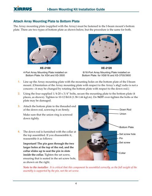
Attach Array <strong>Mounting</strong> Plate to Bottom Plate<br />
The Array mounting plate (supplied with the Array) must be fastened to the I-beam mount’s bottom<br />
plate. There are two types of bottom plate as shown below, but the procedure is the same for both.<br />
XE-2100<br />
4-Port Array <strong>Mounting</strong> Plate installed on<br />
Bottom Plate: for <strong><strong>XS</strong>4</strong> and <strong>XS</strong>-<strong>3500</strong><br />
XE-2120<br />
8/16-Port Array <strong>Mounting</strong> Plate installed on<br />
Bottom Plate: for <strong>XS</strong>8/16 and <strong>XS</strong>-3700/3900<br />
1. Line up the Array mounting plate with the mounting holes on the bottom plate of the I-beam<br />
mount. (Orientation of the Array mounting plate with respect to the Array’s abg2 radio is not a<br />
concern—it may be changed by rotating the bottom plate with respect to the down rod.)<br />
2. Using the four supplied 1/4-20 x 3/4” bolts, secure the mounting plate to the bottom plate (4<br />
places, as shown). Tighten to 10-12 lbf.ft (1.38-1.66 kgf.m). Do NOT over-tighten the bolts or the<br />
plate may be damaged.<br />
3. Attach the bottom plate to the threaded end<br />
of the down rod, screwing it on firmly.<br />
Make sure that the union ring is screwed<br />
down tightly.<br />
Down Rod<br />
Union<br />
4. The down rod is furnished with the collar at<br />
the top assembled. If you disassemble it,<br />
reassemble it as follows:<br />
Important! The pin goes through the two<br />
larger holes at the top of the rod, and the<br />
collar slides up to seat the pin in slots<br />
inside the collar. Tighten the set screw,<br />
ensuring that is seated in the set screw hole,<br />
as shown on the right.<br />
Bottom Plate<br />
Set screw hole<br />
Pin<br />
Set screw<br />
Collar<br />
Note to the installer: It is critical that this component be assembled correctly, as the full weight of the<br />
assembly is supported by the pin, not the set screw.<br />
4