56007-01, VSP-VS520SZ-DCAH - Balboa Direct
56007-01, VSP-VS520SZ-DCAH - Balboa Direct
56007-01, VSP-VS520SZ-DCAH - Balboa Direct

You also want an ePaper? Increase the reach of your titles
YUMPU automatically turns print PDFs into web optimized ePapers that Google loves.
<strong>VS520SZ</strong> Tech Sheet<br />
<strong>Balboa</strong> Instruments<br />
System PN <strong>56007</strong>-<strong>01</strong><br />
System Model # <strong>VSP</strong>-<strong>VS520SZ</strong>-<strong>DCAH</strong><br />
Software Version # 43<br />
EPN # 2808<br />
Base PCBA - PN 55151-<strong>01</strong><br />
PCB VS500Z - PN 22972 Rev C or D<br />
Base Panels<br />
Serial Standard – PN 53189-<strong>01</strong><br />
Template used: 40600_R.pdf 04/16/2008<br />
<strong>56007</strong>-<strong>01</strong>_B.pdf 08/27/2008<br />
Page 1<br />
<strong>56007</strong>-<strong>01</strong>_B
System Revision History<br />
System PN EPN Date Requested By Changes Made<br />
<strong>56007</strong>-<strong>01</strong> 2808 08.27.2008 <strong>Balboa</strong> Software update to version 43<br />
<strong>56007</strong>-<strong>01</strong> 2808 09.30.08 <strong>Balboa</strong> Tech sheet changes to clarify Circ Pump behavior<br />
Page 2<br />
<strong>56007</strong>-<strong>01</strong>_B
Basic System Features and Functions<br />
Power Requirements<br />
<br />
<br />
System Outputs (As Manufactured)<br />
<br />
<br />
<br />
<br />
<br />
AV <br />
<br />
Optional Devices<br />
<br />
Additional Options<br />
<br />
<br />
<br />
<br />
<br />
<br />
<br />
<br />
K8<br />
J2<br />
J1<br />
W2<br />
W3<br />
J1A<br />
J2A<br />
1<br />
U4<br />
K5<br />
2 3<br />
J12<br />
J10<br />
FUSE<br />
J18<br />
J13<br />
J60<br />
J22<br />
J7<br />
J8<br />
J44<br />
BALBOA INSTRUMENTS, INC.<br />
VS500Z<br />
P/N 22972 REV D<br />
2-SPD<br />
EXT RLY<br />
EXT.<br />
RLY<br />
AUX. F<br />
SEN. A<br />
SEN. B<br />
VAC<br />
MADE IN U.S.A<br />
COPYRIGHT 2005<br />
Page 3<br />
<strong>56007</strong>-<strong>01</strong>_B
C<br />
G<br />
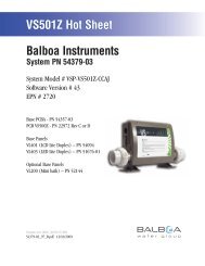
Basic System Features and Functions<br />
Any time you change a DIP Switch, other than A1, you must reset Persistent<br />
Memory for your new DIP Switch Settings changes to take effect. If you do<br />
not reset Persistent Memory, your system may function improperly.<br />
To reset Persistent Memory:<br />
Power down by disconnecting power source from spa.<br />
Put a jumper across J43, covering both pins. (See illustration below)<br />
Power up by connecting power source to spa.<br />
Wait until “ ” is displayed on your panel.<br />
Power down again.<br />
Remove jumper from J43 (May also move to cover 1 pin only)<br />
Power up again.<br />
About Persistent Memory and Time of Day Retention:<br />
This system uses memory that doesn’t require a battery to store a variety of<br />
settings. What we refer to as Persistent Memory stores the filter settings,<br />
the set temperature, and the heat mode.<br />
Persistent Memory is not used for Time of Day. Only models with a<br />
Serial Deluxe panel installed (VS5xxDZ and GS5xxDZ) can display the<br />
time. However, during power loss to the spa, the system will lose the<br />
correct time, and reset to 12:00 PM when power is restored.<br />
Power Up Display Sequence<br />
Upon power up, you should see the following on the display:<br />
Three numbers in a row, which are the SSID (the System Software<br />
ID). The third display of these numbers is the Software Version,<br />
which should match the version of your system. For example, if these<br />
three numbers are , that is a VS511SZ at version 38.<br />
Displayed next is: “ ” (indicating the system is configured for<br />
a heater between 3 and 6 kW) or “ ” (indicating the system is<br />
configured for a heater effectively* between 1 and 3 kW).<br />
“ ” should appear for all VS models running at 240VAC.<br />
“ ” should appear for all VS models running at 120VAC, as well<br />
as all GS models. (*A heater which is rated at 4 kW at 240VAC will<br />
function as a 1 kW heater at 120VAC.)<br />
“ ” will appear to signal the start of Priming Mode.<br />
At this point, the power up sequence is complete. Refer to the Reference<br />
Card for the VS or GS System model of your spa for information about how<br />
the spa operates from this point on, including how to adjust the Time of<br />
Day if using a Serial Deluxe style panel.<br />
J43<br />
E.GND<br />
K6<br />
G C<br />
F4 FUSE .3A 250V<br />
J23<br />
K1<br />
W1<br />
SWITCHBANK<br />
T1A<br />
K3<br />
K2<br />
F2<br />
W4<br />
E.GND<br />
J50<br />
G C<br />
J6<br />
G C<br />
SWITCHBANK A<br />
F7<br />
J17/26<br />
S1 TST<br />
S1<br />
W7<br />
FUSE 20A 250V<br />
K8<br />
K9<br />
J43<br />
J46<br />
J60 J22<br />
J6 J7 J8<br />
TST<br />
EXT.<br />
RLY<br />
J2<br />
AUX. F<br />
J1<br />
SEN. A<br />
J47<br />
G C<br />
W2<br />
W3<br />
J1A<br />
J2A<br />
SEN. B<br />
U4<br />
J29<br />
G C<br />
J13<br />
BALBOA INSTRUMENTS, INC. 2-SPD<br />
J44 VS500Z<br />
EXT RLY<br />
P/N 22972 REV D<br />
VAC<br />
MADE IN U.S.A<br />
COPYRIGHT 2005<br />
J43 on VS5xxZ and VS300 Series Main Board Shown.<br />
J43 on GS5xxZ Series is located in approximately the same position.<br />
K5<br />
1 2 3<br />
J12<br />
J20<br />
F1<br />
J10<br />
FUSE 3A 250V<br />
J18<br />
J26<br />
J90<br />
J50<br />
LINE<br />
BLK AC<br />
W1<br />
K4<br />
K1<br />
VS100<br />
P/N 22964_B MADE IN U.S.A.<br />
© 2006<br />
PUMP<br />
T0.25A 250V<br />
<strong>Balboa</strong><br />
J58<br />
G C<br />
J23<br />
NEUTRAL<br />
F2<br />
J57<br />
HEATER<br />
OZONE<br />
J29<br />
G C<br />
WHT AC<br />
K3<br />
J9<br />
TST<br />
K2<br />
K5<br />
SWITCHBANK A<br />
F4<br />
J6 J43<br />
S1<br />
TST<br />
SWITCHBANK A<br />
RST<br />
J43 on VS100/GS100 Series Main Board Shown.<br />
J6<br />
J43<br />
RST<br />
F5, F3A 250V<br />
J13 J12<br />
J7<br />
SEN. A<br />
J8<br />
SEN. B<br />
J18<br />
U4<br />
G<br />
J20<br />
C<br />
J1<br />
Page 4<br />
<strong>56007</strong>-<strong>01</strong>_B
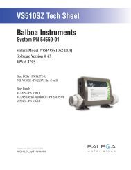
Wiring Configuration and DIP Settings<br />
Setup 1 (As Manufactured)<br />
<br />
<br />
<br />
<br />
<br />
<br />
AV <br />
<br />
CLASS G FUSE 30A<br />
J66<br />
J65<br />
J11<br />
F5<br />
WHT AC<br />
J15 J16 J25 J63 J64<br />
NEUTRAL<br />
WHITE<br />
BLK AC<br />
J61 J62<br />
K6 J23<br />
K1<br />
2-Spd P1<br />
G C<br />
W1<br />
F4 FUSE .3A 250V<br />
W4<br />
T1<br />
J50<br />
Audio Visual<br />
G C<br />
Blower<br />
G C<br />
F7 FUSE 20A 250V<br />
J17/26<br />
W7<br />
K8<br />
K9<br />
J1<br />
J46<br />
J47<br />
Circ.Pump<br />
G C<br />
W2<br />
W3<br />
J1A<br />
J29<br />
Ozone<br />
G C<br />
K5<br />
J20<br />
12V<br />
Light<br />
G C<br />
F1<br />
J10<br />
FUSE 3A 250V<br />
K4<br />
TORQUE<br />
RANGE<br />
FOR TB1:<br />
27-30 IN. LBS.<br />
HOT<br />
BLACK<br />
HOT<br />
RED<br />
TB1<br />
K3<br />
K2<br />
J2<br />
J2A<br />
VS5xxS mode<br />
2 3<br />
1<br />
U4 J12<br />
J18<br />
J32 J33 J34 J35<br />
J43<br />
<strong>Balboa</strong><br />
J100<br />
J36 J37<br />
RED AC<br />
HTR2 HTR1<br />
J1<strong>01</strong><br />
5.5 kW<br />
F2<br />
E.GND<br />
SWITCHBANK A<br />
J60 J22<br />
J6 J7 J8<br />
S1 TST<br />
EXT.<br />
RLY<br />
AUX. F<br />
SEN. A SEN. B<br />
J44<br />
BALBOA INSTRUMENTS, INC.<br />
VS500Z<br />
P/N 22972 REV D<br />
VAC MADE IN U.S.A<br />
COPYRIGHT 2005<br />
2-SPD<br />
EXT RLY<br />
J13<br />
X-P332<br />
PN 55137<br />
J7<br />
W1<br />
J1<br />
R B W G<br />
2-Spd P2<br />
F30A 480V<br />
P/N 22909 REV B<br />
J6<br />
WARNING: Main Power to system should be turned OFF BEFORE adjusting DIP switches.<br />
WARNING: Persistent Memory (J43) must be RESET to allow new DIP switch settings to take effect. (See Persistent Memory page)<br />
SSID #<br />
100<br />
98<br />
43<br />
A1, Test Mode OFF<br />
A2, See Table 1<br />
A3, N/A<br />
A5,<br />
Panel Button Assignments<br />
1=Mode<br />
5=Pump 1<br />
2=Temp Up<br />
6=Pump 2<br />
3=Temp Down 7=Unused 7=J17/26<br />
4=Light<br />
A7, J17/26 Disabled Enabled<br />
A9, See Circ Mode Table<br />
A10, See Table 1<br />
Panel Button Positions<br />
7<br />
1 2<br />
5 6 4<br />
3<br />
1<br />
2<br />
3<br />
5<br />
2<br />
6<br />
1<br />
4 3<br />
Page 5<br />
VS51x/VS5xxS/VS5xxD<br />
Compatible<br />
J12<br />
1 2 3<br />
J43<br />
Memory<br />
Reset<br />
4<br />
5<br />
7<br />
6<br />
Wiring Color Key<br />
120 Volt Connections<br />
240 Volt Connections<br />
Black AC Jumpers<br />
12 Volt Connections<br />
Relay Control Wires<br />
Board Connector Key<br />
1 Typically Line voltage<br />
2 Typically Line voltage for 2-speed pumps<br />
3 Neutral (Common)<br />
4 Ground<br />
Note flat sides in connector<br />
<strong>56007</strong>-<strong>01</strong>_B
DIP Switches and Jumpers Definitions<br />
SSID 100 98 43<br />
DIP Switch Key<br />
A1 Test Mode (normally OFF)<br />
A2+A10 Control amp draw requirements (See Table 1)<br />
A3 N/A (must be OFF)<br />
A4 Aux Freeze (must be OFF)<br />
A5+A9 Pump 1 speeds and Circ Modes:<br />
A5 A9 Circ Mode Pump 1 Speed<br />
OFF OFF Non-circ 2-speed<br />
ON OFF Circ "acts like Pump 1 low" (filters/polls/ect) 1-speed<br />
OFF ON 24 hours with 3°F shut-off 1-speed<br />
ON ON 24 hours with 3°F shut-off 2-speed<br />
A6 “ON” position: 50Hz operation<br />
“OFF” position: 60Hz operation<br />
A7 “ON” position: J17/26 Enabled for Blower or 1-speed Pump.*<br />
“OFF” position: J17/26 Disabled.<br />
A8 “ON” position: temperature is displayed in degrees Celsius<br />
“OFF” position: temperature is displayed in degrees Fahrenheit<br />
* Panel with button layout is not compatible when A7 is ON.<br />
Base Model <strong>VS520SZ</strong><br />
Table 1 # of Hi-Speed<br />
Pumps/Blower<br />
Before Heat Disabled<br />
A2 A10<br />
OFF OFF 0<br />
ON OFF 1<br />
OFF ON 2<br />
ON ON 3<br />
Alert:<br />
2-speed Pump 2 is required, uses<br />
X-P332 expander board.<br />
To add Blower or 1-speed Pump 3,<br />
use J17/26.<br />
Jumper Key<br />
J12 Factory set. DO NOT MOVE.<br />
Jumper must be on Pins 1 and 2 for VS51xZ/VS52xZ/VS5xxSZ/VS5xxDZ software.<br />
Jumper must be on Pins 2 and 3 for VS50xZ software.<br />
J43 When jumper is placed on 2 pins during power-up, system will reset persistent memory.<br />
Leave on 1 pin only to enable persistent memory feature.<br />
WARNING:<br />
Setting DIP switches incorrectly may cause abnormal system behavior and/or damage to system components.<br />
Refer to Switchbank illustration on Wiring Configuration page for correct settings for this system.<br />
Contact <strong>Balboa</strong> if you require additional configuration pages added to this tech sheet.<br />
Panel Button Positions<br />
Aux Panel Information<br />
7<br />
1 2<br />
2<br />
4<br />
7<br />
Supports 2-button aux panel<br />
5 6 4<br />
3<br />
1<br />
3<br />
5<br />
6<br />
VX20<br />
5<br />
6<br />
6<br />
5<br />
2<br />
4 3<br />
1<br />
Supports 4-button aux panel<br />
Panel Button Assignments<br />
VX40S<br />
5 6 7 4<br />
1=Mode<br />
2=Temp Up<br />
3=Temp Down<br />
4=Light<br />
5=Pump 1<br />
6=Pump 2<br />
7=J17/26 (when A7 is ON)<br />
Page 6<br />
<strong>56007</strong>-<strong>01</strong>_B
W<br />
W<br />
Ozone Connections<br />
Ozone Connector Voltage: The VS500Z circuit board is factory configured to deliver a preset voltage (120V or<br />
240V) to the on-board ozone connector (J29). See the ratings table on the wiring diagram attached to the cover<br />
of the enclosure for the configured voltage. For 240V output W2 connects to Red AC and for 120V output W2<br />
connects to White AC.<br />
The voltage to the ozone connector can be changed in the field if required. W2 just needs to be set for the<br />
required voltage.<br />
WARNING: Changing the voltage of the ozone connector also effects the voltage supplied to the circ<br />
pump connector (J47). Any equipment controlled by that connector may be damaged if the wrong voltage<br />
is selected.<br />
<strong>Balboa</strong> Ozone Generator: If the board is set up to operate a 120V ozone generator, the connector on the ozone<br />
generator is likely to be configured correctly, but should be compared to the illustration below.<br />
If a 240V ozone generator is required, be sure the red wire in the ozone cord is positioned in the connector next<br />
to the green ground wire as described below.<br />
Note: A special tool is required to remove the pins from the connector body once they are snapped in place.<br />
Check with your <strong>Balboa</strong> Account Manager for information on purchasing a pin-removal tool.<br />
<strong>Balboa</strong> Ozone connector configuration for 120V 60Hz<br />
Line - Black conductor<br />
Use this slot for the leftover Red conductor<br />
Common - Install the White conductor here for 120V ozone<br />
Ground (Green) conductor<br />
B<br />
G<br />
<strong>Balboa</strong> Ozone connector configuration for 240V 60Hz<br />
Line - Black conductor<br />
Use this slot for the leftover White conductor<br />
Common - Install the Red conductor here for 240V ozone<br />
Ground (Green) conductor<br />
Flat sides of sockets as shown<br />
B<br />
G<br />
FUSE 20A 250V<br />
J46<br />
J47<br />
J29<br />
K8<br />
J1<br />
Circ.Pump<br />
G W B R<br />
W2<br />
W3<br />
J1A<br />
K5<br />
J20<br />
12V<br />
Light<br />
F1<br />
FUSE 3A 250V<br />
Line - Black conductor<br />
Use this slot for the leftover conductor<br />
Common - Red for 240V or White for 120V ozone (See W2 wire)<br />
Ground (Green) conductor<br />
W2 wire determines voltage<br />
J10<br />
Page 7<br />
<strong>56007</strong>-<strong>01</strong>_B
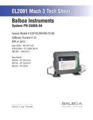
Serial Standard Panel Configurations<br />
Blower<br />
Mode<br />
Warm<br />
Heat<br />
Jets 1 Jets 2<br />
Light<br />
Cool<br />
Serial Standard<br />
PN 53189-<strong>01</strong> with Overlay PN 10430<br />
Connects to Main Board terminal J1<br />
Page 8<br />
<strong>56007</strong>-<strong>01</strong>_B