IBM 2250 Display Unit Model 4 - All about the IBM 1130 Computing ...
IBM 2250 Display Unit Model 4 - All about the IBM 1130 Computing ...
IBM 2250 Display Unit Model 4 - All about the IBM 1130 Computing ...
Create successful ePaper yourself
Turn your PDF publications into a flip-book with our unique Google optimized e-Paper software.
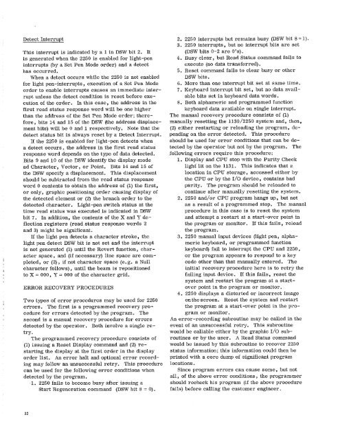
Detect Interrupt<br />
This interrupt is indicated by a 1 in DSW bit 2. It<br />
is generated when <strong>the</strong> <strong>2250</strong> is enabled for light-pen<br />
interrupts (by a Set Pen Mode order) and a detect<br />
has occurred.<br />
When a detect occurs while <strong>the</strong> <strong>2250</strong> is not enabled<br />
for light pen-interrupts, execution of a Set Pen Mode<br />
order to enable interrupts causes an immediate interrupt<br />
unless <strong>the</strong> detect condition is reset before execution<br />
of <strong>the</strong> order. In this case, <strong>the</strong> address in <strong>the</strong><br />
first read status response word will be one higher<br />
than <strong>the</strong> address of <strong>the</strong> Set Pen Mode order; <strong>the</strong>refore,<br />
bits 14 and 15 of <strong>the</strong> DSW (<strong>the</strong> address displacement<br />
bits) will be 0 and 1 respectively. Note that <strong>the</strong><br />
detect status bit is always reset by a Detect Interrupt.<br />
If <strong>the</strong> <strong>2250</strong> is enabled for light-pen detects when<br />
a detect occurs, <strong>the</strong> address in <strong>the</strong> first read status<br />
response word depends on <strong>the</strong> type of data detected.<br />
Bits 9 and 10 of <strong>the</strong> DSW identify <strong>the</strong> display mode<br />
ad Character, Vector, or Point. Bits 14 and 15 of<br />
<strong>the</strong> DSW specify a displacement. This displacement<br />
should be subtracted from <strong>the</strong> read status response<br />
word 0 contents to obtain <strong>the</strong> address of (1) <strong>the</strong> first,<br />
or only, graphic positioning order causing display of<br />
<strong>the</strong> detected element or (2) <strong>the</strong> branch order to <strong>the</strong><br />
detected character. Light-pen switch status at <strong>the</strong><br />
time read status was executed is indicated in DSW<br />
bit 7. In addition, <strong>the</strong> contents of <strong>the</strong> X and Y deflection<br />
registers (read status response words 2<br />
and 3) might be significant.<br />
If <strong>the</strong> light pen detects a character stroke, <strong>the</strong><br />
light pen detect DSW bit is not set and <strong>the</strong> interrupt<br />
is not generated (1) until <strong>the</strong> Revert function, character<br />
space, and (if necessary) line space are completed,<br />
or (2), if not character space (e.g. a Null<br />
character follows), until <strong>the</strong> beam is repositioned<br />
to X = 000, Y = 000 of <strong>the</strong> character grid.<br />
ERROR RECOVERY PROCEDURES<br />
Two types of error procedures may be used for <strong>2250</strong><br />
errors. The first is a programmed recovery procedure<br />
for errors detected by <strong>the</strong> program. The<br />
second is a manual recovery procedure for errors<br />
detected by <strong>the</strong> operator. Both involve a single retry<br />
Ṫhe programmed recovery procedure consists of<br />
(1) issuing a Reset <strong>Display</strong> command and (2) restarting<br />
<strong>the</strong> display at <strong>the</strong> first order in <strong>the</strong> display<br />
order list. An error halt and optional error recording<br />
may follow an unsuccessful retry. This procedure<br />
can be used for <strong>the</strong> following error conditions when<br />
detected by <strong>the</strong> program.<br />
1. <strong>2250</strong> fails to become busy after issuing a<br />
Start Regeneration command (DSW bit 8 = 0).<br />
2. <strong>2250</strong> interrupts but remains busy (DSW bit 8=1).<br />
3. <strong>2250</strong> interrupts, but no interrupt bits are set<br />
(DSW bits 0-2 are O's).<br />
4. Busy clear, but Read Status command fails to<br />
execute (no data transferred).<br />
5. Reset command fails to clear busy or o<strong>the</strong>r<br />
DSW bits.<br />
6. More than one interrupt bit set at same time.<br />
7. Keyboard interrupt bit set, but no data available<br />
bits set in keyboard data words.<br />
8. Both alphameric and programmed function<br />
keyboard data available on single interrupt.<br />
The manual recovery procedure consists of (1)<br />
manually resetting <strong>the</strong> <strong>1130</strong>/<strong>2250</strong> system and, <strong>the</strong>n,<br />
(2) ei<strong>the</strong>r restarting or reloading <strong>the</strong> program, depending<br />
on <strong>the</strong> error detected. This procedure<br />
should be used for error conditions that can be detected<br />
by <strong>the</strong> operator but not by <strong>the</strong> program. The<br />
following errors require this procedure:<br />
1. <strong>Display</strong> and CPU stop with <strong>the</strong> Parity Check<br />
light lit on <strong>the</strong> 1131. This indicates that a<br />
location in CPU storage, accessed ei<strong>the</strong>r by<br />
<strong>the</strong> CPU or by <strong>the</strong> I/0 device, contains bad<br />
parity. The program should be reloaded to<br />
continue after manually resetting <strong>the</strong> system.<br />
2. <strong>2250</strong> and/or CPU program hangs up, but not<br />
as a result of a programmed stop. The manual<br />
procedure in this case is to reset <strong>the</strong> system<br />
and attempt a restart at a start-over point in<br />
<strong>the</strong> program or monitor. If this fails, reload<br />
<strong>the</strong> program.<br />
3. <strong>2250</strong> manual input devices (light pen, alphameric<br />
keyboard, or programmed function<br />
keyboard) fail to interrupt <strong>the</strong> CPU and <strong>2250</strong>,<br />
or <strong>the</strong> program appears to respond to a key<br />
code o<strong>the</strong>r than that manually entered. The<br />
initial recovery procedure here is to retry <strong>the</strong><br />
failing input device. If this fails, reset <strong>the</strong><br />
system and restart <strong>the</strong> program at a startover<br />
point in <strong>the</strong> program or monitor.<br />
4. <strong>2250</strong> displays a distorted or incorrect image<br />
on <strong>the</strong> screen. Reset <strong>the</strong> system and restart<br />
<strong>the</strong> program at a start-over point in <strong>the</strong> program<br />
or monitor.<br />
An error-recording subroutine may be called in <strong>the</strong><br />
event of an unsuccessful retry. This subroutine<br />
would be callable ei<strong>the</strong>r by <strong>the</strong> graphic I/0 subroutines<br />
or by <strong>the</strong> user. A Read Status command<br />
would be issued by this subroutine to recover <strong>2250</strong><br />
status information; this information could <strong>the</strong>n be<br />
printed with a core dump of significant program<br />
locations.<br />
Since program errors can cause some, but not<br />
all, of <strong>the</strong> above error conditions, <strong>the</strong> programmer<br />
should recheck his program (if <strong>the</strong> above procedure<br />
fails) before calling <strong>the</strong> customer engineer.<br />
32


