IBM 2250 Display Unit Model 4 - All about the IBM 1130 Computing ...
IBM 2250 Display Unit Model 4 - All about the IBM 1130 Computing ...
IBM 2250 Display Unit Model 4 - All about the IBM 1130 Computing ...

Create successful ePaper yourself
Turn your PDF publications into a flip-book with our unique Google optimized e-Paper software.
<strong>Display</strong> program information consists of orders<br />
and data. Orders ei<strong>the</strong>r initiate a <strong>2250</strong> operation<br />
or establish a mode. Order-initiated operations<br />
include point and vector plotting, branching, and<br />
CPU interrupt generation. Two orders, Set<br />
Graphic Mode and Set Pen Mode, establish a<br />
Graphic mode and a Light Pen mode respectively.<br />
The <strong>2250</strong> is always in one of two Graphic modes<br />
and in one of four Light Pen modes.<br />
Data is defined as information that does not<br />
contain an operation code. Character stroke words<br />
are <strong>the</strong> only data received by <strong>the</strong> <strong>2250</strong>. Although<br />
a character stroke word may contain one or more<br />
control bits, <strong>the</strong>se bits are used directly to perform<br />
an operation.<br />
SUBROUTINES<br />
Single-level subroutines (linkage from <strong>the</strong> main<br />
order program to <strong>the</strong> order subroutine and return<br />
to <strong>the</strong> main order program) are used frequently in<br />
graphic application. Thus, facilities for a rapid<br />
(unconditional) branch to a subroutine and return<br />
from <strong>the</strong> subroutine are provided. Since characters<br />
are similar to single-level subroutines, rapid<br />
branching significantly reduces character display<br />
time.<br />
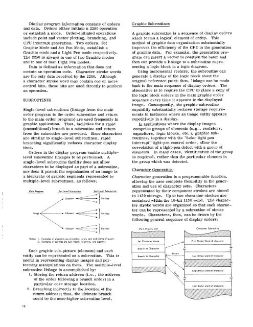
Orders in <strong>the</strong> display program enable multiplelevel<br />
subroutine linkages to be performed. A<br />
single-level subroutine facility does not allow<br />
characters to be displayed as part of a subroutine,<br />
nor does it permit <strong>the</strong> organization of an image in<br />
a hierarchy of graphic segments represented by<br />
multiple-level subroutines, as follows:<br />
Main Program<br />
Image<br />
1st Level Subroutine 2nd Level Subroutine<br />
Entities<br />
–I. 1 Entities<br />
Graphic Subroutines<br />
A graphic subroutine is a sequence of display orders<br />
which forms a logical element of entity. This<br />
method of graphic data organization substantially<br />
improves <strong>the</strong> efficiency of <strong>the</strong> CPU in <strong>the</strong> generation<br />
of graphic data. For example, <strong>the</strong> generation program<br />
can insert a vector to position <strong>the</strong> beam and<br />
<strong>the</strong>n can provide a linkage to a subroutine representing<br />
a logic block in a logic diagram.<br />
Using incremental vectors, <strong>the</strong> subroutine can<br />
generate a display of <strong>the</strong> logic block <strong>about</strong> <strong>the</strong><br />
original reference point; <strong>the</strong>n, linkage can be made<br />
back to <strong>the</strong> main sequence of display orders. The<br />
alternative is to require <strong>the</strong> CPU to place a copy of<br />
<strong>the</strong> logic block orders in <strong>the</strong> main graphic order<br />
sequence every time it appears in <strong>the</strong> displayed<br />
image. Consequently, <strong>the</strong> graphic subroutine<br />
capability substantially reduces storage requirements<br />
in instances where an image entity appears<br />
repetitively in a display.<br />
In applications where <strong>the</strong> display images<br />
comprise groups of elements (e. g. , resistors,<br />
capacitors, logic blocks, etc. ), graphic subroutines,<br />
toge<strong>the</strong>r with <strong>the</strong> "defer light pen<br />
interrupt" light-pen control order, allow <strong>the</strong><br />
correlation of a light-pen detect with a group of<br />
elements. In many cases, identification of <strong>the</strong> group<br />
is required, ra<strong>the</strong>r than <strong>the</strong> particular element in<br />
<strong>the</strong> group which was detected.<br />
Character Generation<br />
Character generation is a programmable function,<br />
allowing <strong>the</strong> user complete flexibility in <strong>the</strong> generation<br />
and use of character sets. Characters<br />
represented by <strong>the</strong>ir component strokes are stored<br />
in <strong>1130</strong> storage. Up to two character strokes are<br />
contained within <strong>the</strong> 16-bit <strong>1130</strong> word. The character<br />
stroke words are organized so that each character<br />
can be represented by a subroutine of stroke<br />
words. Characters, <strong>the</strong>n, can be drawn by <strong>the</strong><br />
following general sequence of display orders:<br />
Entities<br />
Main <strong>Display</strong> List<br />
Character Subroutine<br />
Notes: 1. Examples of elements are elevation, plan, and end-views of a part.<br />
2. Examples of entities are bolt heads, brackets, and supports.<br />
zz'<br />
First Stroke Word of character<br />
Each graphic sub-picture (element) and each<br />
entity can be represented as a subroutine. This is<br />
useful in representing display images and performing<br />
manipulations on <strong>the</strong>m. The multiple-level<br />
subroutine linkage is accomplished by:<br />
1. Storing <strong>the</strong> return address (i. e. , <strong>the</strong> address<br />
of <strong>the</strong> order following a branch order) in a<br />
particular core storage location.<br />
2. Branching indirectly to <strong>the</strong> location of <strong>the</strong><br />
return address; thus, <strong>the</strong> ultimate branch<br />
would be <strong>the</strong> next-higher subroutine level.<br />
wir 4<br />
R evert<br />
V<br />
Last stroke word of character<br />
18