8W-01 WIRING DIAGRAM INFORMATION
8W-01 WIRING DIAGRAM INFORMATION
8W-01 WIRING DIAGRAM INFORMATION

You also want an ePaper? Increase the reach of your titles
YUMPU automatically turns print PDFs into web optimized ePapers that Google loves.
HB <strong>8W</strong>-<strong>01</strong> <strong>WIRING</strong> <strong>DIAGRAM</strong> <strong>INFORMATION</strong> <strong>8W</strong> - <strong>01</strong> - 1<br />
<strong>8W</strong>-<strong>01</strong> <strong>WIRING</strong> <strong>DIAGRAM</strong> <strong>INFORMATION</strong><br />
<strong>WIRING</strong> <strong>DIAGRAM</strong> <strong>INFORMATION</strong><br />
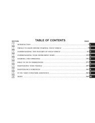
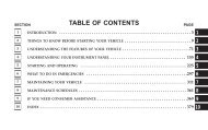
DESCRIPTION<br />
DESCRIPTION - HOW TO USE <strong>WIRING</strong><br />
<strong>DIAGRAM</strong>S..................................1<br />
DESCRIPTION - CIRCUIT <strong>INFORMATION</strong> ......6<br />
DESCRIPTION - CIRCUIT FUNCTIONS ........6<br />
DESCRIPTION - SECTION IDENTIFICATION<br />
AND <strong>INFORMATION</strong>..........................7<br />
DESCRIPTION - CONNECTOR, GROUND<br />
AND SPLICE <strong>INFORMATION</strong>..................8<br />
WARNING<br />
WARNINGS - GENERAL ......................8<br />
DIAGNOSIS AND TESTING - <strong>WIRING</strong><br />
HARNESS ...................................9<br />
STANDARD PROCEDURE<br />
STANDARD PROCEDURE -<br />
ELECTROSTATIC DISCHARGE (ESD)<br />
SENSITIVE DEVICES........................10<br />
STANDARD PROCEDURE - TESTING OF<br />
VOLTAGE POTENTIAL.......................11<br />
STANDARD PROCEDURE - TESTING FOR<br />
CONTINUITY...............................11<br />
<strong>WIRING</strong> <strong>DIAGRAM</strong> <strong>INFORMATION</strong><br />
DESCRIPTION<br />
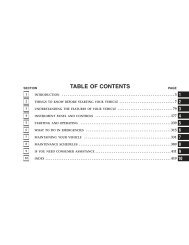
TABLE OF CONTENTS<br />
DESCRIPTION - HOW TO USE <strong>WIRING</strong> <strong>DIAGRAM</strong>S<br />
page page<br />
STANDARD PROCEDURE - TESTING FOR A<br />
SHORT TO GROUND........................11<br />
STANDARD PROCEDURE - TESTING FOR A<br />
SHORT TO GROUND ON FUSES<br />
POWERING SEVERAL LOADS...............12<br />
STANDARD PROCEDURE - TESTING FOR A<br />
VOLTAGE DROP............................12<br />
SPECIAL TOOLS<br />
<strong>WIRING</strong>/TERMINAL .........................13<br />
CONNECTOR<br />
REMOVAL ....................................14<br />
INSTALLATION ...............................17<br />
DIODE<br />
REMOVAL ....................................18<br />
INSTALLATION ...............................18<br />
TERMINAL<br />
REMOVAL ....................................19<br />
INSTALLATION ...............................19<br />
WIRE<br />
STANDARD PROCEDURE - WIRE SPLICING ....20<br />
DaimlerChrysler Corporation wiring diagrams are designed to provide information regarding the vehicles wiring content.<br />
In order to effectively use the wiring diagrams to diagnose and repair DaimlerChrysler Corporation vehicles, it<br />
is important to understand all of their features and characteristics.<br />
Diagrams are arranged such that the power (B+) side of the circuit is placed near the top of the page, and the<br />
ground (B-) side of the circuit is placed near the bottom of the page.<br />
All switches, components, and modules are shown in the at rest position with the doors closed and the key<br />
removed from the ignition.<br />
Components are shown two ways. A solid line around a component indicates that the component is complete. A<br />
dashed line around the component indicates that the component is being shown is not complete. Incomplete components<br />
have a reference number to indicate the page where the component is shown complete.<br />
It is important to realize that no attempt is made on the diagrams to represent components and wiring as they<br />
appear on the vehicle. For example, a short piece of wire is treated the same as a long one. In addition, switches<br />
and other components are shown as simply as possible, with regard to function only.
<strong>8W</strong> - <strong>01</strong> - 2 <strong>8W</strong>-<strong>01</strong> <strong>WIRING</strong> <strong>DIAGRAM</strong> <strong>INFORMATION</strong> HB
HB <strong>8W</strong>-<strong>01</strong> <strong>WIRING</strong> <strong>DIAGRAM</strong> <strong>INFORMATION</strong> <strong>8W</strong> - <strong>01</strong> - 3
<strong>8W</strong> - <strong>01</strong> - 4 <strong>8W</strong>-<strong>01</strong> <strong>WIRING</strong> <strong>DIAGRAM</strong> <strong>INFORMATION</strong> HB<br />
SYMBOLS<br />
International symbols are used throughout the wiring diagrams. These symbols are consistent with those being used<br />
around the world.
HB <strong>8W</strong>-<strong>01</strong> <strong>WIRING</strong> <strong>DIAGRAM</strong> <strong>INFORMATION</strong> <strong>8W</strong> - <strong>01</strong> - 5
<strong>8W</strong> - <strong>01</strong> - 6 <strong>8W</strong>-<strong>01</strong> <strong>WIRING</strong> <strong>DIAGRAM</strong> <strong>INFORMATION</strong> HB<br />
TERMINOLOGY<br />
This is a list of terms and definitions used in the wiring diagrams.<br />
LHD..............................................................Left Hand Drive Vehicles<br />
RHD ............................................................Right Hand Drive Vehicles<br />
ATX ...............................................Automatic Transmissions-Front Wheel Drive<br />
MTX ................................................Manual Transmissions-Front Wheel Drive<br />
AT.................................................Automatic Transmissions-Rear Wheel Drive<br />
MT ..................................................Manual Transmissions-Rear Wheel Drive<br />
SOHC ........................................................Single Over Head Cam Engine<br />
DOHC .......................................................Double Over Head Cam Engine<br />
Export ...............................Vehicles Built For Sale In Markets Other Than North America<br />
Except Export ..........................................Vehicles Built For Sale In North America<br />
DESCRIPTION - CIRCUIT <strong>INFORMATION</strong><br />
Each wire shown in the diagrams contains a code which identifies the main circuit, a specific part of the main circuit,<br />
gage of wire, and color. An example would be A 2 18 LB/YL. This is a Battery Feed circuit, level two, eighteen<br />
gauge, light blue with a yellow tracer.<br />
WIRE COLOR CODE CHART<br />
COLOR CODE COLOR<br />
BL BLUE<br />
BK BLACK<br />
BR BROWN<br />
DB DARK BLUE<br />
DG DARK GREEN<br />
GY GRAY<br />
LB LIGHT BLUE<br />
LG LIGHT GREEN<br />
OR ORANGE<br />
PK PINK<br />
RD RED<br />
TN TAN<br />
VT VIOLET<br />
WT WHITE<br />
YL YELLOW<br />
* WITH TRACER<br />
DESCRIPTION - CIRCUIT FUNCTIONS<br />
All circuits in the diagrams use an alpha/numeric code to identify the wire and it’s function. To identify which circuit<br />
code applies to a system, refer to the Circuit Identification Code Chart. This chart shows the main circuits only and<br />
does not show the secondary codes that may apply to some models.
HB <strong>8W</strong>-<strong>01</strong> <strong>WIRING</strong> <strong>DIAGRAM</strong> <strong>INFORMATION</strong> <strong>8W</strong> - <strong>01</strong> - 7<br />
CIRCUIT IDENTIFICATION CODE CHART<br />
CIRCUIT FUNCTION<br />
A BATTERY FEED<br />
B BRAKE CONTROLS<br />
C CLIMATE CONTROLS<br />
D DIAGNOSTIC CIRCUITS<br />
E DIMMING ILLUMINATION<br />
CIRCUITS<br />
F FUSED CIRCUITS<br />
G MONITORING CIRCUITS<br />
(GAUGES)<br />
H MULTIPLE<br />
I NOT USED<br />
J OPEN<br />
K POWERTRAIN CONTROL<br />
MODULE<br />
L EXTERIOR LIGHTING<br />
M INTERIOR LIGHTING<br />
N MULTIPLE<br />
O NOT USED<br />
P POWER OPTION (BATTERY<br />
FEED)<br />
Q POWER OPTIONS (IGNITION<br />
FEED)<br />
R PASSIVE RESTRAINT<br />
S SUSPENSION/STEERING<br />
T TRANSMISSION/TRANSAXLE/<br />
TRANSFER CASE<br />
U OPEN<br />
V SPEED CONTROL, WIPER/<br />
WASHER<br />
W WIPERS<br />
X AUDIO SYSTEMS<br />
Y TEMPORARY<br />
Z GROUNDS<br />
DESCRIPTION - SECTION IDENTIFICATION AND <strong>INFORMATION</strong><br />
The wiring diagrams are grouped into individual sections. If a component is most likely found in a particular group,<br />
it will be shown complete (all wires, connectors, and pins) within that group. For example, the Auto Shutdown Relay<br />
is most likely to be found in Group 30, so it is shown there complete. It can, however, be shown partially in another<br />
group if it contains some associated wiring.<br />
Splice diagrams in Section <strong>8W</strong>-70 show the entire splice and provide references to other sections the splices<br />
serves. Section <strong>8W</strong>-70 only contains splice diagrams that are not shown in their entirety somewhere else in the<br />
wiring diagrams.<br />
Section <strong>8W</strong>-80 shows each connector and the circuits involved with that connector. The connectors are identified<br />
using the name/number on the diagram pages.
<strong>8W</strong> - <strong>01</strong> - 8 <strong>8W</strong>-<strong>01</strong> <strong>WIRING</strong> <strong>DIAGRAM</strong> <strong>INFORMATION</strong> HB<br />
DESCRIPTION - CONNECTOR, GROUND AND SPLICE <strong>INFORMATION</strong><br />
CAUTION: Not all connectors are serviced. Some connectors are serviced only with a harness. A typical<br />
example might be the Supplemental Restraint System connectors. Always check parts availability before<br />
attempting a repair.<br />
IDENTIFICATION<br />
In-line connectors are identified by a number, as follows:<br />
• In-line connectors located in the engine compartment are C100 series numbers.<br />
• In-line connectors located in the instrument panel area are C200 series numbers.<br />
• In-line connectors located in the body are C300 series numbers.<br />
• Jumper harness connectors are C400 series numbers.<br />
• Grounds and ground connectors are identified with a “G” and follow the same series numbering as the in-line<br />
connectors.<br />
• Splices are identified with an “S” and follow the same series numbering as the in-line connectors. In addition,<br />
S0<strong>01</strong>–S099 numbers are located in the engine compartment.<br />
• Component connectors are identified by the component name instead of a number. Multiple connectors on a<br />
component use a C1, C2, etc. identifier.<br />
LOCATIONS<br />
Section <strong>8W</strong>-91 contains connector/ground/splice location illustrations. The illustrations contain the connector name<br />
(or number)/ground number/splice number and component identification. Connector/ground/splice location charts in<br />
section <strong>8W</strong>-91 reference the figure numbers of the illustrations.<br />
The abbreviation T/O is used in the component location section to indicate a point in which the wiring harness<br />
branches out to a component. The abbreviation N/S means Not Shown in the illustrations<br />
WARNING<br />
WARNINGS - GENERAL<br />
WARNINGS provide information to prevent personal injury and vehicle damage. Below is a list of general warnings<br />
that should be followed any time a vehicle is being serviced.<br />
WARNING: Always wear safety glasses for eye protection.<br />
WARNING: Use safety stands anytime a procedure requires being under a vehicle.<br />
WARNING: Be sure that the ignition switch always is in the off position, unless the procedure requires it to<br />
be on.<br />
WARNING: Set the parking brake when working on any vehicle. An automatic transmission should be in<br />
park. A manual transmission should be in neutral.<br />
WARNING: Operate the engine only in a well-ventilated area.<br />
WARNING: Keep away from moving parts when the engine is running, especially the fan and belts.<br />
WARNING: To prevent serious burns, avoid contact with hot parts such as the radiator, exhaust manifold(s),<br />
tail pipe, catalytic converter and muffler.
HB <strong>8W</strong>-<strong>01</strong> <strong>WIRING</strong> <strong>DIAGRAM</strong> <strong>INFORMATION</strong> <strong>8W</strong> - <strong>01</strong> - 9<br />
WARNING: Do not allow flame or sparks near the battery. Gases are always present in and around the battery.<br />
WARNING: Always remove rings, watches, loose hanging jewelry and avoid loose clothing.<br />
DIAGNOSIS AND TESTING - <strong>WIRING</strong> HARNESS<br />
TROUBLESHOOTING TOOLS<br />
When diagnosing a problem in an electrical circuit there are several common tools necessary. These tools are listed<br />
and explained below.<br />
• Jumper Wire - This is a test wire used to connect two points of a circuit. It can be used to bypass an open in<br />
a circuit.<br />
WARNING: Never use a jumper wire across a load, such as a motor, connected between a battery feed and<br />
ground.<br />
• Voltmeter - Used to check for voltage on a circuit. Always connect the black lead to a known good ground and<br />
the red lead to the positive side of the circuit.<br />
CAUTION: Most of the electrical components used in today’s vehicles are Solid State. When checking voltages<br />
in these circuits, use a meter with a 10 - megohm or greater impedance rating.<br />
• Ohmmeter - Used to check the resistance between two points of a circuit. Low or no resistance in a circuit<br />
means good continuity.<br />
CAUTION: Most of the electrical components used in today’s vehicles are Solid State. When checking resistance<br />
in these circuits use a meter with a 10 - megohm or greater impedance rating. In addition, make sure<br />
the power is disconnected from the circuit. Circuits that are powered up by the vehicle’s electrical system<br />
can cause damage to the equipment and provide false readings.<br />
• Probing Tools - These tools are used for probing<br />
terminals in connectors. Select the proper size<br />
tool from Special Tool Package 6807, and insert<br />
the probing end (2) into the terminal being<br />
tested. Use the other end of the tool (1) to insert<br />
the meter probe.<br />
INTERMITTENT AND POOR CONNECTIONS<br />
Most intermittent electrical problems are caused by faulty electrical connections or wiring. It is also possible for a<br />
sticking component or relay to cause a problem. Before condemning a component or wiring assembly, check the<br />
following items.<br />
• Connectors are fully seated<br />
• Spread terminals, or terminal push out<br />
• Terminals in the wiring assembly are fully seated into the connector/component and locked into position<br />
• Dirt or corrosion on the terminals. Any amount of corrosion or dirt could cause an intermittent problem<br />
• Damaged connector/component casing exposing the item to dirt or moisture<br />
• Wire insulation that has rubbed through causing a short to ground<br />
• Some or all of the wiring strands broken inside of the insulation<br />
• Wiring broken inside of the insulation
<strong>8W</strong> - <strong>01</strong> - 10 <strong>8W</strong>-<strong>01</strong> <strong>WIRING</strong> <strong>DIAGRAM</strong> <strong>INFORMATION</strong> HB<br />
TROUBLESHOOTING <strong>WIRING</strong> PROBLEMS<br />
When troubleshooting wiring problems there are six steps which can aid in the procedure. The steps are listed and<br />
explained below. Always check for non-factory items added to the vehicle before doing any diagnosis. If the vehicle<br />
is equipped with these items, disconnect them to verify these add-on items are not the cause of the problem.<br />
1. Verify the problem.<br />
2. Verify any related symptoms. Do this by performing operational checks on components that are in the same<br />
circuit. Refer to the wiring diagrams.<br />
3. Analyze the symptoms. Use the wiring diagrams to determine what the circuit is doing, where the problem most<br />
likely is occurring and where the diagnosis will continue.<br />
4. Isolate the problem area.<br />
5. Repair the problem area.<br />
6. Verify the proper operation. For this step, check for proper operation of all items on the repaired circuit. Refer to<br />
the wiring diagrams.<br />
STANDARD PROCEDURE<br />
STANDARD PROCEDURE - ELECTROSTATIC DISCHARGE (ESD) SENSITIVE<br />
DEVICES<br />
All ESD sensitive components are solid state and a<br />
symbol is used to indicate this. When handling any<br />
component with this symbol, comply with the following<br />
procedures to reduce the possibility of electrostatic<br />
charge build up on the body and inadvertent discharge<br />
into the component. If it is not known whether the part<br />
is ESD sensitive, assume that it is.<br />
1. Always touch a known good ground before handling<br />
the part. This should be repeated while handling<br />
the part and more frequently after sliding<br />
across a seat, sitting down from a standing position,<br />
or walking a distance.<br />
2. Avoid touching electrical terminals of the part, unless instructed to do so by a written procedure.<br />
3. When using a voltmeter, be sure to connect the ground lead first.<br />
4. Do not remove the part from it’s protective packing until it is time to install the part.<br />
5. Before removing the part from it’s package, ground the package to a known good ground on the vehicle.
HB <strong>8W</strong>-<strong>01</strong> <strong>WIRING</strong> <strong>DIAGRAM</strong> <strong>INFORMATION</strong> <strong>8W</strong> - <strong>01</strong> - 11<br />
STANDARD PROCEDURE - TESTING OF VOLTAGE POTENTIAL<br />
1. Connect the ground lead of a voltmeter to a known<br />
good ground.<br />
2. Connect the other lead of the voltmeter to the<br />
selected test point. The vehicle ignition may need<br />
to be turned ON to check voltage. Refer to the<br />
appropriate test procedure.<br />
STANDARD PROCEDURE - TESTING FOR CONTINUITY<br />
1. Remove the fuse (1) for the circuit being checked<br />
or, disconnect the battery.<br />
2. Connect one lead of the ohmmeter to one side of<br />
the circuit being tested<br />
3. Connect the other lead to the other end of the circuit<br />
being tested. Low or no resistance means<br />
good continuity.<br />
STANDARD PROCEDURE - TESTING FOR A SHORT TO GROUND<br />
1. Remove the fuse and disconnect all items involved with the fuse.<br />
2. Connect a test light or a voltmeter across the terminals of the fuse.<br />
3. Starting at the fuse block, wiggle the wiring harness about six to eight inches apart and watch the voltmeter/test<br />
lamp.<br />
4. If the voltmeter registers voltage or the test lamp glows, there is a short to ground in that general area of the<br />
wiring harness.
<strong>8W</strong> - <strong>01</strong> - 12 <strong>8W</strong>-<strong>01</strong> <strong>WIRING</strong> <strong>DIAGRAM</strong> <strong>INFORMATION</strong> HB<br />
STANDARD PROCEDURE - TESTING FOR A SHORT TO GROUND ON FUSES<br />
POWERING SEVERAL LOADS<br />
1. Refer to the wiring diagrams and disconnect or isolate all items on the suspected fused circuits.<br />
2. Replace the blown fuse.<br />
3. Supply power to the fuse by turning ON the ignition switch or re-connecting the battery.<br />
4. Start connecting or energizing the items in the fuse circuit one at a time. When the fuse blows the circuit with the<br />
short to ground has been isolated.<br />
STANDARD PROCEDURE - TESTING FOR A VOLTAGE DROP<br />
1. Connect the positive lead of the voltmeter to the<br />
side of the circuit closest to the battery.<br />
2. Connect the other lead of the voltmeter to the other<br />
side of the switch, component or circuit.<br />
3. Operate the item.<br />
4. The voltmeter will show the difference in voltage<br />
between the two points.
HB <strong>8W</strong>-<strong>01</strong> <strong>WIRING</strong> <strong>DIAGRAM</strong> <strong>INFORMATION</strong> <strong>8W</strong> - <strong>01</strong> - 13<br />
SPECIAL TOOLS<br />
<strong>WIRING</strong>/TERMINAL<br />
PROBING TOOL PACKAGE 6807<br />
TERMINAL PICK TOOL SET 6680<br />
TERMINAL REMOVING TOOLS 6932 AND 8638<br />
TERMINAL REMOVING TOOL 6934
<strong>8W</strong> - <strong>01</strong> - 14 <strong>8W</strong>-<strong>01</strong> <strong>WIRING</strong> <strong>DIAGRAM</strong> <strong>INFORMATION</strong> HB<br />
CONNECTOR<br />
REMOVAL<br />
1. Disconnect battery.<br />
2. Release Connector Lock (2).<br />
3. Disconnect the connector (3) being repaired from<br />
its mating half/component.<br />
4. Remove the dress cover (if applicable) (1).
HB <strong>8W</strong>-<strong>01</strong> <strong>WIRING</strong> <strong>DIAGRAM</strong> <strong>INFORMATION</strong> <strong>8W</strong> - <strong>01</strong> - 15<br />
5. Release the Secondary Terminal Lock, if required (1).
<strong>8W</strong> - <strong>01</strong> - 16 <strong>8W</strong>-<strong>01</strong> <strong>WIRING</strong> <strong>DIAGRAM</strong> <strong>INFORMATION</strong> HB<br />
1 - TYPICAL CONNECTOR<br />
2 - PICK FROM SPECIAL TOOL KIT 6680<br />
3 - APEX CONNECTOR<br />
4 - PICK FROM SPECIAL TOOL KIT 6680<br />
5 - AUGAT CONNECTOR<br />
6 - SPECIAL TOOL 6932<br />
7 - MOLEX CONNECTOR<br />
8 - SPECIAL TOOL 6742<br />
9 - THOMAS AND BETTS CONNECTOR<br />
10 - SPECIAL TOOL 6934<br />
11 - TYCO CONNECTOR<br />
12 - SPECIAL TOOL 8638<br />
6. Position the connector locking finger away from the terminal using the proper special tool. Pull on the wire to<br />
remove the terminal from the connector.
HB <strong>8W</strong>-<strong>01</strong> <strong>WIRING</strong> <strong>DIAGRAM</strong> <strong>INFORMATION</strong> <strong>8W</strong> - <strong>01</strong> - 17<br />
INSTALLATION<br />
1. Insert the removed terminal in the same cavity on the repair connector.<br />
2. Repeat steps for each terminal in the connector, being sure that all wires are inserted into the proper cavities.<br />
For additional connector pin-out identification, refer to the wiring diagrams.<br />
3. When the connector is re-assembled, the secondary terminal lock must be placed in the locked position to prevent<br />
terminal push out.<br />
4. Replace dress cover (if applicable).<br />
5. Connect connector to its mating half/component.<br />
6. Connect battery and test all affected systems.
<strong>8W</strong> - <strong>01</strong> - 18 <strong>8W</strong>-<strong>01</strong> <strong>WIRING</strong> <strong>DIAGRAM</strong> <strong>INFORMATION</strong> HB<br />
DIODE<br />
REMOVAL<br />
1. Disconnect the battery.<br />
2. Locate the diode in the harness, and remove the<br />
protective covering.<br />
3. Remove the diode from the harness, pay attention<br />
to the current flow direction (1) (2) (3).<br />
INSTALLATION<br />
1. Remove the insulation from the wires in the harness. Only remove enough insulation to solder in the new diode.<br />
2. Install the new diode in the harness, making sure current flow is correct. If necessary, refer to the appropriate<br />
wiring diagram for current flow.<br />
3. Solder the connection together using rosin core type solder only. Do not use acid core solder.<br />
4. Tape the diode to the harness using electrical tape. Make sure the diode is completely sealed from the elements.<br />
5. Re-connect the battery and test affected systems.
HB <strong>8W</strong>-<strong>01</strong> <strong>WIRING</strong> <strong>DIAGRAM</strong> <strong>INFORMATION</strong> <strong>8W</strong> - <strong>01</strong> - 19<br />
TERMINAL<br />
REMOVAL<br />
1. Follow steps for removing terminals described in the connector removal section.<br />
2. Cut the wire 6 inches from the back of the connector.<br />
INSTALLATION<br />
1. Select a wire from the terminal repair kit that best matches the color and gage of the wire being repaired.<br />
2. Cut the repair wire to the proper length and remove one–half (1/2) inch of insulation.<br />
3. Splice the repair wire to the wire harness (see wire splicing procedure) (Refer to 8 - ELECTRICAL/<strong>WIRING</strong> DIA-<br />
GRAM <strong>INFORMATION</strong>/WIRE - STANDARD PROCEDURE).<br />
4. Insert the repaired wire into the connector.<br />
5. Install the connector locking wedge, if required, and reconnect the connector to its mating half/component.<br />
6. Re-tape the wire harness starting at 1–1/2 inches behind the connector and 2 inches past the repair.<br />
7. Connect battery and test all affected systems.
<strong>8W</strong> - <strong>01</strong> - 20 <strong>8W</strong>-<strong>01</strong> <strong>WIRING</strong> <strong>DIAGRAM</strong> <strong>INFORMATION</strong> HB<br />
WIRE<br />
STANDARD PROCEDURE - WIRE SPLICING<br />
When splicing a wire, it is important that the correct gage be used as shown in the wiring diagrams.<br />
1. Remove one-half (1/2) inch of insulation from each<br />
wire that needs to be spliced.<br />
2. Place a piece of adhesive lined heat shrink tubing<br />
on one side of the wire. Make sure the tubing will<br />
be long enough to cover and seal the entire repair<br />
area.<br />
3. Place the strands of wire overlapping each other<br />
inside of the splice clip (1).<br />
4. Using crimping tool (1), Mopar p/n 05<strong>01</strong>9912AA,<br />
crimp the splice clip and wires together.<br />
5. Solder (3) the connection (2) together using rosin<br />
core type solder (1) only.<br />
CAUTION: DO NOT USE ACID CORE SOLDER.<br />
6. Center the heat shrink tubing (2) over the joint and<br />
heat using a heat gun. Heat the joint until the tubing<br />
is tightly sealed and sealant (1) comes out of<br />
both ends of the tubing.