8W-01 WIRING DIAGRAM INFORMATION
8W-01 WIRING DIAGRAM INFORMATION
8W-01 WIRING DIAGRAM INFORMATION
You also want an ePaper? Increase the reach of your titles
YUMPU automatically turns print PDFs into web optimized ePapers that Google loves.
<strong>8W</strong> - <strong>01</strong> - 8 <strong>8W</strong>-<strong>01</strong> <strong>WIRING</strong> <strong>DIAGRAM</strong> <strong>INFORMATION</strong> HB<br />
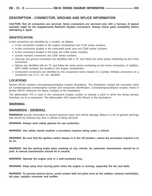
DESCRIPTION - CONNECTOR, GROUND AND SPLICE <strong>INFORMATION</strong><br />
CAUTION: Not all connectors are serviced. Some connectors are serviced only with a harness. A typical<br />
example might be the Supplemental Restraint System connectors. Always check parts availability before<br />
attempting a repair.<br />
IDENTIFICATION<br />
In-line connectors are identified by a number, as follows:<br />
• In-line connectors located in the engine compartment are C100 series numbers.<br />
• In-line connectors located in the instrument panel area are C200 series numbers.<br />
• In-line connectors located in the body are C300 series numbers.<br />
• Jumper harness connectors are C400 series numbers.<br />
• Grounds and ground connectors are identified with a “G” and follow the same series numbering as the in-line<br />
connectors.<br />
• Splices are identified with an “S” and follow the same series numbering as the in-line connectors. In addition,<br />
S0<strong>01</strong>–S099 numbers are located in the engine compartment.<br />
• Component connectors are identified by the component name instead of a number. Multiple connectors on a<br />
component use a C1, C2, etc. identifier.<br />
LOCATIONS<br />
Section <strong>8W</strong>-91 contains connector/ground/splice location illustrations. The illustrations contain the connector name<br />
(or number)/ground number/splice number and component identification. Connector/ground/splice location charts in<br />
section <strong>8W</strong>-91 reference the figure numbers of the illustrations.<br />
The abbreviation T/O is used in the component location section to indicate a point in which the wiring harness<br />
branches out to a component. The abbreviation N/S means Not Shown in the illustrations<br />
WARNING<br />
WARNINGS - GENERAL<br />
WARNINGS provide information to prevent personal injury and vehicle damage. Below is a list of general warnings<br />
that should be followed any time a vehicle is being serviced.<br />
WARNING: Always wear safety glasses for eye protection.<br />
WARNING: Use safety stands anytime a procedure requires being under a vehicle.<br />
WARNING: Be sure that the ignition switch always is in the off position, unless the procedure requires it to<br />
be on.<br />
WARNING: Set the parking brake when working on any vehicle. An automatic transmission should be in<br />
park. A manual transmission should be in neutral.<br />
WARNING: Operate the engine only in a well-ventilated area.<br />
WARNING: Keep away from moving parts when the engine is running, especially the fan and belts.<br />
WARNING: To prevent serious burns, avoid contact with hot parts such as the radiator, exhaust manifold(s),<br />
tail pipe, catalytic converter and muffler.


