8W-01 WIRING DIAGRAM INFORMATION
8W-01 WIRING DIAGRAM INFORMATION
8W-01 WIRING DIAGRAM INFORMATION

Create successful ePaper yourself
Turn your PDF publications into a flip-book with our unique Google optimized e-Paper software.
<strong>8W</strong> - <strong>01</strong> - 20 <strong>8W</strong>-<strong>01</strong> <strong>WIRING</strong> <strong>DIAGRAM</strong> <strong>INFORMATION</strong> HB<br />
WIRE<br />
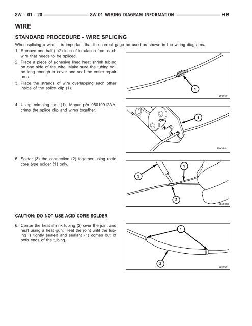
STANDARD PROCEDURE - WIRE SPLICING<br />
When splicing a wire, it is important that the correct gage be used as shown in the wiring diagrams.<br />
1. Remove one-half (1/2) inch of insulation from each<br />
wire that needs to be spliced.<br />
2. Place a piece of adhesive lined heat shrink tubing<br />
on one side of the wire. Make sure the tubing will<br />
be long enough to cover and seal the entire repair<br />
area.<br />
3. Place the strands of wire overlapping each other<br />
inside of the splice clip (1).<br />
4. Using crimping tool (1), Mopar p/n 05<strong>01</strong>9912AA,<br />
crimp the splice clip and wires together.<br />
5. Solder (3) the connection (2) together using rosin<br />
core type solder (1) only.<br />
CAUTION: DO NOT USE ACID CORE SOLDER.<br />
6. Center the heat shrink tubing (2) over the joint and<br />
heat using a heat gun. Heat the joint until the tubing<br />
is tightly sealed and sealant (1) comes out of<br />
both ends of the tubing.