You also want an ePaper? Increase the reach of your titles
YUMPU automatically turns print PDFs into web optimized ePapers that Google loves.
Wire Harness Installation Instructions<br />
For Installing:<br />
Part # 30714<br />
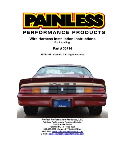
1978-1981 Camaro Tail Light Harness<br />
Perfect Performance Products, LLC<br />
<strong>Painless</strong> Performance Products Division<br />
2501 Ludelle Street<br />
Fort Worth, TX 76105-1036<br />
800-423-9696 phone – 817-244-4024 fax<br />
Web Site: www.painlessperformance.com<br />
E-Mail: painless@painlessperformance.com
This harness is a direct replacement for the tail harness found in our 1974-1977<br />
Camaro 18 circuit Chassis Harness, <strong>Painless</strong> part # 20113. Using the inline connectors<br />
and terminals supplied with this kit, this tail harness can also be used on any vehicle<br />
with a factory chassis harness or any aftermarket chassis harness, like a <strong>Painless</strong><br />
universal chassis harness. For those simply replacing the tail harness on a 20113<br />
harness, skip now to “1978-1981 Tail Harness Installation” page 5.<br />
If installing this harness in a vehicle<br />
with a factory chassis harness, a factory<br />
wiring diagram may be helpful.<br />
To apply the best crimp possible to<br />
the terminals supplied in this kit, a pair of<br />
roll over/jaw style crimpers will be needed.<br />
<strong>Painless</strong> offers a pair of these crimpers as<br />
part # 70900.<br />
This style of crimper will roll the<br />
straps of the terminal over into the copper<br />
wire, providing a strong connection with<br />
great contact. Pliers or other styles<br />
crimpers will simply fold the terminal straps<br />
over onto the copper. While this may<br />
provide you with a good contact and<br />
possibly work, it is not the proper way.<br />
Other tools needed will be a pair of<br />
wire strippers and a pair of crimpers used<br />
to crimp insulated terminals. This will<br />
normally be on the same tool.<br />
Begin by examining the section label on the supplied tail harness to<br />
ensure you have the correct tail harness for your application. The section<br />
label should read “1978-1981”.<br />
2
In the trunk, locate the following 5 wires running from the front to the rear<br />
of the car:<br />
TAN- This is the wire going to the fuel gauge. Universal <strong>Painless</strong> harnesses, this will be<br />
a wire with #939 printed on it.<br />
LIGHT GREEN- This is a power wire for the reverse lights. Universal <strong>Painless</strong><br />
harnesses, this will be a wire with #956 printed on it.<br />
BROWN- This is a power wire from the headlight switch for the marker, tail and license<br />
plate lights. Universal <strong>Painless</strong> harnesses, this will be a wire with #927 or<br />
#929 printed on it, depending on the harness.<br />
3
YELLOW- This is the power wire from the turn signal switch for the left turn signal.<br />
Universal <strong>Painless</strong> harnesses, this will be a wire with #949 printed on it.<br />
GREEN- This is the power wire from the turn signal switch for the right turn signal.<br />
Universal <strong>Painless</strong> harnesses, this will be a wire with #948 printed on it.<br />
There will also be dome light wires (white and orange wires) and a fuel pump wire (in<br />
aftermarket harnesses), these will remain untouched.<br />
Begin by cutting these 5 wires about 6-12” behind the driver side marker<br />
lamp. This will be towards the front of the car, seen circled in the photo<br />
below. Do not cut more than 12” back or the new tail harness may not<br />
reach.<br />
With the wires now cut you can remove all of the tail<br />
sockets from the vehicle, do not discard any of<br />
these factory sockets until the install of this new<br />
harness is complete.<br />
Strip ¼” of wire insulation from each<br />
wire that is coming from the front of<br />
the vehicle and install a silicone seal<br />
from the parts kit. (Photo 1)<br />
Position the terminal so the longer<br />
straps will fit around the silicone seal,<br />
while the smaller straps will cradle the<br />
exposed copper (Photo 2)<br />
Using the appropriate jaw, crimp the<br />
terminal onto the copper wire. (Photos<br />
3 & 4)<br />
Using a larger jaw, you can now crimp<br />
the terminal to the seal. (Photos 5 & 6)<br />
4
Insert the following wires into the 4 pin connector: Tan/fuel sender to PIN<br />
A, PIN B will remain empty, Light Green/reverse to PIN C, and<br />
Brown/marker light to Pin D<br />
Insert the following wires into the 3 pin connector: Yellow/left turn to PIN<br />
A, Green/left turn to PIN B, PIN C will remain empty<br />
Now that both connectors are connected to the chassis harness, flip the<br />
terminal position piece on each connector around the wires and click it into<br />
place.<br />
1978-1981 TAIL HARNESS INSTALLATION<br />
Begin the installation by removing the tail light lenses from the car to gain<br />
access to the hole on the driver side for harness pass through, seen<br />
circled below.<br />
5
Insert the two black connectors found on the tail harness, seen in the<br />
middle of the page, and feed the harness into the trunk until the grommet<br />
that has been pre-installed on the tail harness is seated in the hole.<br />
In the trunk, plug the new <strong>Painless</strong> Tail Harness into the two connectors<br />
you have just installed onto the wires on your chassis harness. Once<br />
connected these connectors can be tucked out of sight, down into the rear<br />
quarter.<br />
You can now move out to the tail light area and route the harness across<br />
the rear of the car. Use the harness clips to secure the harness. Take<br />
notice on how the harness in the photo routes down under the filler neck<br />
to several clips that are located behind the bumper and then back up to<br />
the passenger side of the gas filler neck.<br />
6
“Driver Side Park Light”<br />
The driver side park light is the next<br />
connection. The park, or marker light as it is<br />
often called, is activated by a power source<br />
coming from the headlight switch. This light<br />
will illuminate any time the headlight switch is<br />
in the PARK or ON position.<br />
The park light requires two wires to work properly. A factory style socket comes<br />
pre-installed and will have a label reading “DRVR. SIDE PARK LIGHT”. The wires<br />
spliced to this molded connector are:<br />
Brown: 18 gauge wire, this is a power wire for the park or marker light function. This<br />
wire will have power anytime the headlight switch is in the Park/Tail Lights ON or<br />
Headlights ON position. This wire, along with all the other wires and splices it is<br />
associated with, can be seen in the 1978-1981 Tail Harness Power diagram on page 3.<br />
Black: 18 gauge wire, this wire provides a ground source for the park light and comes<br />
from a splice that is tied to a series of other splices that tie all the grounds in this<br />
harness together. This wire, along with all the other ground wires and splices, can be<br />
seen in the 1978-1981 Tail Harness Grounds diagram on page 3.<br />
This socket requires a single filament bulb, while supplied in the kit, it can<br />
also be purchased from just about any auto parts store under part # 194.<br />
Looking at the back of the tail light lens, you will see the park light<br />
opening. You will see that it has a keyed opening to correspond with the<br />
tabs on the socket, as seen in the photo on page 9.<br />
Insert the lamp socket of the <strong>Painless</strong> harness into the park light housing<br />
and turn ¼ turn to lock the socket in place.<br />
“Left Brake/Tail Light”<br />
This connection will have a section label<br />
reading “BRAKE/ TAIL LIGHT” and a three wire<br />
socket pre-installed. The three wires found in this<br />
socket are:<br />
Light Blue- 18 gauge wire, this wire is the brake<br />
light power. This wire will have battery power<br />
anytime the brake pedal is pressed. This wire can be seen in the 1978-1981 Tail<br />
Harness Power diagram on page 3.<br />
Brown: 18 gauge wire, this is a power wire for the tail light function. This wire will have<br />
power anytime the headlight switch is in the Park/Tail Lights ON or Headlights ON<br />
position. This wire, along with all the other wires and splice it is associated with, can be<br />
seen in the 1978-1981 Tail Harness Power diagram on page 3.<br />
7
Black: 18 gauge wire, this wire provides a ground source for the Turn/Brake/Tail Light<br />
and comes from a splice that is tied to a series of other splices that tie all the grounds in<br />
this harness together. This wire, along with all the other ground wires and splices, can<br />
be seen in the 1978-1981 Tail Harness Grounds diagram on page 3.<br />
“Left Turn Signal”<br />
This socket requires a dual filament bulb, while supplied in the kit, it can<br />
also be purchased from just about any auto parts store under part # 1157.<br />
The turn signal will be the brighter of the two filaments.<br />
With the bulb in place, insert the socket into the lens. Tuning the socket ¼<br />
turn will lock it in place. Notice the keying on the bucket and the socket will<br />
only allow the socket to be installed one way.<br />
This connection will have a section label<br />
reading “L. TURN” and a 2 wire socket preinstalled.<br />
The three wires found in this socket<br />
are:<br />
Yellow- 18 gauge wire, this wire is the turn<br />
signal power. This wire will have interrupted<br />
switched power from the turn flasher any time<br />
the left turn signal is activated and interrupted<br />
battery power from the hazard flasher any time the hazard switch is in the ON position.<br />
This wire will also have battery power anytime the brake pedal is pressed. This wire can<br />
be seen in the 1978-1981 Tail Harness Power diagram on page 3.<br />
Black: 18 gauge wire, this wire provides a ground source for the Turn/Brake/Tail Light<br />
and comes from a splice that is tied to a series of other splices that tie all the grounds in<br />
this harness together. This wire, along with all the other ground wires and splices, can<br />
be seen in the 1978-1981 Tail Harness Grounds diagram on page 3.<br />
This socket requires a dual filament bulb, while supplied in the kit, it can<br />
also be purchased from just about any auto parts store under part # 1157.<br />
The turn signal will be the brighter of the two filaments.<br />
With the bulb in place, insert the socket into the lens. Tuning the socket ¼<br />
turn will lock it in place. Notice the keying on the bucket and the socket will<br />
only allow the socket to be installed one way.<br />
“Reverse Light”<br />
This will be the lens closest to the center of<br />
the car, lens with the clear center. This connection<br />
will have a section label reading “LEFT REVERSE<br />
LIGHT” and will have a two wire socket preinstalled.<br />
The two wires in this socket are:<br />
8
Light Green- 18 gauge wire, this wire will provide power to the reverse or back up<br />
lights. This wire receives power from the reverse switch and will have power anytime<br />
the shifter is in the REVERSE position. This wire can be seen in the 1978-1981 Tail<br />
Harness Power diagram on page 3.<br />
Black: 18 gauge wire, this wire provides a ground source for the reverse light and<br />
comes from a splice that is tied to a series of other splices that tie all the grounds in this<br />
harness together. This wire, along with all the other ground wires and splices, can be<br />
seen in the 1978-1981 Tail Harness Grounds diagram on page 3.<br />
This socket requires a single filament bulb, while supplied in the kit, it can<br />
also be purchased from just about any auto parts store under part # 1156.<br />
With the bulb in place, insert the socket into the bottom of the lens.<br />
Turning the socket ¼ turn will lock it in place. Notice the keying on the<br />
bucket and the socket will only allow the socket to be installed one way.<br />
“License Plate Lights”<br />
The plate lights are the next connections needing<br />
to be made. These lights are tied to the rear marker lights<br />
and will illuminate the license plate during low light<br />
conditions when the headlight switch is on.<br />
The wires in the <strong>Painless</strong> harness for this function<br />
will have labels reading “PLATE LIGHT”. These two wires<br />
will have lamp sockets pre-installed, they are:<br />
9
Brown: 18 gauge wires these are power wires for the license plate light function. These<br />
wires will have power anytime the headlight switch is in the Park/Tail Lights ON or<br />
Headlights ON position. This wire, along with all the other wires and splices it is<br />
associated with, can be seen in the 1978-1981 Tail Harness Power diagram on page 3.<br />
Black: 18 gauge wires, these wires provide a ground source for the license plate lights<br />
and comes from a splice that is tied to a series of other splices that tie all the grounds in<br />
this harness together. This wire, along with all the other ground wires and splices, can<br />
be seen in the 1978-1981 Tail Harness Grounds diagram on page 3.<br />
“Ground”<br />
This socket requires a single filament bulb, while supplied in the kit, it can<br />
also be purchased from just about any auto parts store under part # 194.<br />
Install the plate light sockets into the plate light lenses, turning ¼ turn to<br />
lock them in place.<br />
The ground connection in the Tail Harness will tie all of the grounds found in the<br />
Tail harness to a common ground source. One wire, marked with a section label reading<br />
“GROUND”, makes up this connection.<br />
Black: 10 gauge wire, this wire provides a ground source for the Tail harness from a<br />
splice that is tied to a series of other splices that tie all the grounds in this harness<br />
together. This wire, along with all the other ground wires and splices, can be seen in the<br />
1978-1981 Tail Harness Grounds diagram on page 3.<br />
“Fuel Sending Unit”<br />
Using a ring terminal from the parts kit, connect this black ground wire to a<br />
good clean chassis ground source, like one of the mounting bolts for the<br />
trunk latch.<br />
The fuel sending unit connection will be a one<br />
wire connection. This wire will send a resisted ground<br />
source from the fuel level sending unit inside the fuel<br />
tank, up to the fuel gage on the dash. This resistance is<br />
based off how much fuel remains in the tank, which<br />
causes the needle on the gauge to move between empty and full.<br />
The wire provided in the Tail Harness will have a section label reading “FUEL<br />
SENDER”. This wire will have a single pin black connector and a grommet pre-installed,<br />
this wire is:<br />
Tan: 18 gauge wire, this wire will a ground signal. It can be seen in the 1978-1981 Tail<br />
Harness Grounds diagram on page 3.<br />
Insert the single pin connector through the small hole located to the lower<br />
right side of the fuel filler neck, seen on the next page. Seat the preinstalled<br />
grommet into the hole. The use of a small flat head screw driver<br />
may be needed to help get the grommet seated properly.<br />
10
Locate the factory wire<br />
coming from the fuel<br />
tank sending unit,<br />
behind the rear<br />
bumper. Connect the<br />
single pin connector<br />
and wire found on the<br />
Tail Harness to this<br />
factory wire.<br />
“Reverse Light”<br />
This will be the lens closest to the center of the<br />
car, lens with the clear center. This connection will<br />
have a section label reading “RIGHT REVERSE<br />
LIGHT” and will have a two wire socket pre-installed.<br />
The two wires in this socket are:<br />
Light Green- 18 gauge wire, this wire will provide<br />
power to the reverse or back up lights. This wire<br />
receives power from the reverse switch and will have power anytime the shifter is in the<br />
REVERSE position. This wire can be seen in the 1978-1981 Tail Harness Power<br />
diagram on page 3.<br />
Black: 18 gauge wire, this wire provides a ground source for the reverse light and<br />
comes from a splice that is tied to a series of other splices that tie all the grounds in this<br />
harness together. This wire, along with all the other ground wires and splices, can be<br />
seen in the 1978-1981 Tail Harness Grounds diagram on page 3.<br />
This socket requires a single filament bulb, while supplied in the kit , it can<br />
also be purchased from just about any auto parts store under part # 1156.<br />
11
With the bulb in place, insert the socket into the bottom of the lens.<br />
Turning the socket ¼ turn will lock it in place. Notice the keying on the<br />
bucket and the socket will only allow the socket to be installed one way.<br />
“Right Turn Signal”<br />
The lens closest to the passenger side<br />
quarter panel will be for the right Turn Signal. This<br />
connection will have a section label reading “R.<br />
TURN/BRAKE TAIL LIGHT” and a three wire<br />
socket pre-installed. The three wires found in this<br />
socket are:<br />
Green- 18 gauge wire, this wire is the turn signal<br />
This wire will have interrupted switched power from the turn flasher any time the right<br />
turn signal is activated and interrupted battery power from the hazard flasher any time<br />
the hazard switch is in the ON position.. This wire can be seen in the 1978-1981 Tail<br />
Harness Power diagram on page 3.<br />
Black: 18 gauge wire, this wire provides a ground source for the turn signal and comes<br />
from a splice that is tied to a series of other splices that tie all the grounds in this<br />
harness together. This wire, along with all the other ground wires and splices, can be<br />
seen in the 1978-1981 Tail Harness Grounds diagram on page 3.<br />
12
“Right Brake/Tail Light”<br />
This socket requires a dual filament bulb, while supplied in the kit, it can<br />
also be purchased from just about any auto parts store under part # 1157.<br />
The turn signal will be the brighter of the two filaments.<br />
With the bulb in place, insert the socket into the bottom of the lens. Tuning<br />
the socket ¼ turn will lock it in place. Notice the keying on the bucket and<br />
the socket will only allow the socket to be installed one way.<br />
This connection will have a section label<br />
reading “ BRAKE/TAIL LIGHT” and a three wire<br />
socket pre-installed. The three wires found in this<br />
socket are:<br />
Light Blue- 18 gauge wire, this wire is the brake<br />
light power. This wire will have battery power<br />
anytime the brake pedal is pressed. This wire can be seen in the 1978-1981 Tail<br />
Harness Power diagram on page 3.<br />
Brown: 18 gauge wire, this is a power wire for the tail light function. This wire will have<br />
power anytime the headlight switch is in the Park/Tail Lights ON or Headlights ON<br />
position. This wire, along with all the other wires and splice it is associated with, can be<br />
seen in the 1978-1981 Tail Harness Power diagram on page 3.<br />
Black: 18 gauge wire, this wire provides a ground source for the Turn/Brake/Tail Light<br />
and comes from a splice that is tied to a series of other splices that tie all the grounds in<br />
this harness together. This wire, along with all the other ground wires and splices, can<br />
be seen in the 1978-1981 Tail Harness Grounds diagram on page 3.<br />
This socket requires a dual filament bulb, while supplied in the kit, it can<br />
also be purchased from just about any auto parts store under part # 1157.<br />
The turn signal will be the brighter of the two filaments.<br />
With the bulb in place, insert the socket into the bottom of the lens. Tuning<br />
the socket ¼ turn will lock it in place. Notice the keying on the bucket and<br />
the socket will only allow the socket to be installed one way.<br />
“Passenger Side Park Light”<br />
The passenger side park light is the last connection.<br />
The park, or marker light as it is often called, is activated by<br />
a power source coming from the headlight switch. This light<br />
will illuminate any time the headlight switch is in the PARK<br />
or ON position.<br />
The park light requires two wires to work properly. A<br />
factory style socket comes pre-installed and will have a label reading “PASS. SIDE<br />
PARK LIGHT”. The wires spliced to this molded connector are:<br />
13
Brown: 18 gauge wire, this is a power wire for the park or marker light function. This<br />
wire will have power anytime the headlight switch is in the Park/Tail Lights ON or<br />
Headlights ON position. This wire, along with all the other wires and splices it is<br />
associated with, can be seen in the 1978-1981 Tail Harness Power diagram on page 3.<br />
Black: 18 gauge wire, this wire provides a ground source for the park light and comes<br />
from a splice that is tied to a series of other splices that tie all the grounds in this<br />
harness together. This wire, along with all the other ground wires and splices, can be<br />
seen in the 1978-1981 Tail Harness Grounds diagram on page 3.<br />
This socket requires a single filament bulb, while supplied in the kit, it can<br />
also be purchased from just about any auto parts store under part # 194.<br />
Looking at the back of the housing you will see that it has a keyed opening<br />
to correspond with the tabs on the socket. (as seen in the photo on page<br />
12)<br />
Insert the lamp socket of the <strong>Painless</strong> harness into the park light housing<br />
and turn ¼ turn to lock the socket in place.<br />
If you have any questions concerning the installation of this harness or having trouble in general, feel free<br />
to call <strong>Painless</strong> Performance Products' tech line at 1-800-423-9696. Calls are answered from 8am to 5pm<br />
central time, Monday thru Friday, except holidays.<br />
We have attempted to provide you with as accurate instructions as possible, and are always concerned<br />
about corrections or improvements that can be made. If you have found any errors or omissions, or if you<br />
simply have comments or suggestions concerning these instructions, please write us at the address<br />
above, send us a fax at (817) 244-4024 or e-mail us at painless@painlessperformance.com. We sincerely<br />
appreciate your business.<br />
Perfect Performance Products, LLC shall in no event be liable in contract or tort (including negligence)<br />
for special, indirect, incidental, or consequential damages, such as but not limited to, loss of property<br />
damage, or any other damages, costs or expenses which might be claimed as the result of the use or<br />
failure of the goods sold hereby, except only the cost of repair or replacement.<br />
14


