SFA Operating and Maintenance Manual - Spring Air Systems Inc.
SFA Operating and Maintenance Manual - Spring Air Systems Inc.
SFA Operating and Maintenance Manual - Spring Air Systems Inc.

Create successful ePaper yourself
Turn your PDF publications into a flip-book with our unique Google optimized e-Paper software.
<strong>SFA</strong> <strong>Operating</strong><br />
<strong>and</strong> <strong>Maintenance</strong><br />
<strong>Manual</strong><br />
___________________________<br />
<strong>Spring</strong> <strong>Air</strong> <strong>Systems</strong> <strong>Inc</strong>., Oakville, Ontario<br />
Phone (905) 338-2999, Fax (905) 338-0179, info@springairsystems.com<br />
www.springairsystems.com
<strong>SFA</strong> <strong>Operating</strong> <strong>and</strong> <strong>Maintenance</strong> <strong>Manual</strong><br />
Table of Contents<br />
General Description 1<br />
Sequence of Operation 3<br />
Receiving, H<strong>and</strong>ling <strong>and</strong> Storage 4<br />
Installation 4<br />
Start Up <strong>and</strong> Operation 5<br />
<strong>Maintenance</strong> 7<br />
<strong>Maintenance</strong> Schedule 8
<strong>SFA</strong> OPERATING AND MAINTENANCE MANUAL<br />
GENERAL DESCRIPTION<br />
The <strong>Spring</strong> <strong>Air</strong> <strong>Systems</strong> <strong>Inc</strong>. <strong>SFA</strong> unit is a commerical ventilation unit. The <strong>SFA</strong> units are<br />
available in sizes ranging from 500 CFM to 10,000 CFM.<br />
The <strong>SFA</strong> unit is constructed specifically for commerical kitchen applications. The unit is available<br />
in the following arrangements.<br />
<strong>SFA</strong>-OV<br />
<strong>SFA</strong>-OH<br />
<strong>SFA</strong>-IGO<br />
<strong>SFA</strong>- IGODX<br />
<strong>SFA</strong>-OHSE<br />
Vertical arrangement no heating<br />
Horizontal arrangement no heating<br />
Horizontal arrangement with heating<br />
Horizontal arrangement with heating <strong>and</strong> DX air conditioning package<br />
Horizontal arrangement with supply <strong>and</strong> exhaust fans<br />
<strong>SFA</strong>-OV & <strong>SFA</strong>-OH<br />
The <strong>SFA</strong>-V <strong>and</strong> <strong>SFA</strong>-H brings unheated air into a commercial kitchen for discharge into a<br />
compensating kitchen exhaust hood or directly into a kitchen that does not require conditioned<br />
air. The unit is complete with motorized damper <strong>and</strong> end switch located in the fresh air inlet of<br />
the <strong>SFA</strong>-H <strong>and</strong> supply air discharge on the <strong>SFA</strong>-V.<br />
<strong>SFA</strong>-IGO<br />
The <strong>SFA</strong>-IGO unit brings heated air into a commercial kitchen. The unit is complete with<br />
motorized damper <strong>and</strong> end switch located in the fresh air inlet, indirect gas fired gravity (or<br />
power) vent burner, with stainless steel exchanger <strong>and</strong> burner complete with intermittent-duty<br />
pilot ignition gas controls for use with natural gas, non-lockup type. Controls to include<br />
modulator/regulator valve, combination main/pilot/manual valve, spark ignition controller,<br />
overheat control <strong>and</strong> low voltage transformer.duct heater The unit is available with two gas<br />
control options.<br />
• Mechanical Burner Control<br />
o Mechanical modulating control system with duct sensing mounted in unit<br />
discharge by <strong>Spring</strong> <strong>Air</strong> <strong>Systems</strong>. Local set point adjustment located in the<br />
burner control panel.<br />
• Modulating Burner Control<br />
o Electronic modulation control with maxitrol duct sensing system with local set<br />
point adjustment located in burner control panel. The ductstat is normally<br />
installed in the heater discharge duct by mechanical contractor.<br />
o Summer/Winter Operation<br />
o The <strong>SFA</strong> burner is controlled by either a summer/winter switch located in the<br />
remote panel or a unit mounted ambient stat set at 65 F. located in the inlet of<br />
the <strong>SFA</strong> unit. When the outside temperature falls below 65 F the burner circuit is<br />
shut off.<br />
<strong>SFA</strong> <strong>Operating</strong> <strong>and</strong> <strong>Maintenance</strong> <strong>Manual</strong> 1
<strong>SFA</strong>-IGODX<br />
The <strong>SFA</strong>-IGOs unit brings both heated air conditioned air into a commercial kitchen. The heated<br />
air conditioned air is directed to kitchen ceiling diffusers or into the makeup air plenum of the<br />
<strong>Spring</strong> <strong>Air</strong> <strong>Systems</strong> exhaust hood.<br />
The unit is complete with direct expansion cooling coil, compressor condenser section with one<br />
or two compressors with cylinder unloading, <strong>and</strong> a two or three stage discharge stat. The unit<br />
comes completely prepipe <strong>and</strong> charged.<br />
The unit also includes a motorized damper <strong>and</strong> end switch located in the fresh air inlet, indirect<br />
gas fired gravity (or power) vent burner, with stainless steel exchanger <strong>and</strong> burner complete with<br />
intermittent-duty pilot ignition gas controls for use with natural gas, non-lockup type. Controls to<br />
include modulator/regulator valve, combination main/pilot/manual valve, spark ignition controller,<br />
overheat control <strong>and</strong> low voltage transformer.duct heater The unit is available with two gas<br />
control options.<br />
• Mechanical Burner Control<br />
o Mechanical modulating control system with duct sensing mounted in unit<br />
discharge by <strong>Spring</strong> <strong>Air</strong> <strong>Systems</strong>. Local set point adjustment located in the<br />
burner control panel.<br />
• Modulating Burner Control<br />
o Electronic modulation control with maxitrol duct sensing system with local set<br />
point adjustment located in burner control panel. The ductstat is normally<br />
installed in the heater discharge duct by mechanical contractor.<br />
o Summer/Winter Operation<br />
o The <strong>SFA</strong> burner is controlled by either a summer/winter switch located in the<br />
remote panel or a unit mounted ambient stat set at 65 F. located in the inlet of<br />
the <strong>SFA</strong> unit. When the outside temperature falls below 65 F the burner circuit is<br />
shut off.<br />
Summer/Winter Operation<br />
The <strong>SFA</strong> burner <strong>and</strong> air conditioning is controlled by either a summer/winter switch located in the<br />
remote RPD-P panel or a unit mounted ambient stat set at 65 F. located in the inlet of the <strong>SFA</strong><br />
unit. When the outside temperature falls below 65 F the burner circuit is shut off.<br />
<strong>SFA</strong>-OHSE<br />
The <strong>SFA</strong>-OHSE unit brings both heated <strong>and</strong> unheated air into a commercial kitchen. The heated<br />
air is directed to kitchen ceiling through a two way adjustable diffuser out the front of the <strong>Spring</strong><br />
<strong>Air</strong> <strong>Systems</strong> hood <strong>and</strong> the unheated air is directed to the compensating section of the hood.<br />
The unit is complete with motorized damper <strong>and</strong> end switch located in the fresh air inlet, supply<br />
fan, motor <strong>and</strong> drives, exhaust fan motor <strong>and</strong> drives, electric heating coil, motor starters,<br />
disconnect switch, supply air filters, exhaust air gravity backdraft damper, <strong>and</strong> remote control<br />
station.<br />
<strong>SFA</strong> <strong>Operating</strong> <strong>and</strong> <strong>Maintenance</strong> <strong>Manual</strong> 2
SEQUENCE OF OPERATION<br />
<strong>SFA</strong>-IGO, <strong>SFA</strong>-IGODX <strong>and</strong> <strong>SFA</strong>-ES<br />
Power is supplied to the motorized damper in the <strong>SFA</strong> unit. Once the damper has opened the<br />
end switch closes sending 120V/1/60 power to the supply fan starter. The <strong>SFA</strong>-IGO <strong>and</strong> <strong>SFA</strong>-<br />
IGODX burner curcuits are also energized. Refer to the indirect gas fired burner manual for more<br />
detailed description of the heater operation.<br />
Summer/Winter Operation<br />
The <strong>SFA</strong> burner <strong>and</strong>/or air conditioning is controlled by either a summer/winter switch located in<br />
the remote RPD-P, panel or an ambient stat located in the fresh air discharge.<br />
Ambientstat<br />
The burner curcuit is activated when the outside temperature is below 65 F. When there is a call<br />
for heat from the ductstat the gas control valve increased gas flow to the burner to increase the<br />
temperature rise until the discharge temperature stat is satisfied.<br />
Should the outside air temperature rise above 65 F the burner curcuit is automatically shut off<br />
<strong>and</strong> the DX air conditioning curcuit is activated.<br />
Summer/Winter Switch<br />
The switch is located on the remote RPD-P panel. The heater operates continuously on<br />
minimum fire when the switch is in the Winter position. When there is a call for heat from the<br />
ductstat the gas control valve increased gas flow to the burner to increase the temperature rise<br />
until the discharge temperature stat is satisfied.<br />
When the switch is in the Summer position the burner curcuit is shut off <strong>and</strong> the DX air<br />
conditioning curcuit is energized.<br />
When power is shut off to the motorized damper the damper closes, the supply fan <strong>and</strong> burner<br />
curcuit shuts off.<br />
<strong>SFA</strong>-V <strong>and</strong> <strong>SFA</strong>-H<br />
Power is supplied to the motorized damper in the <strong>SFA</strong> unit. Once the damper has opened the<br />
end switch closes sending 120V/1/60 power to the supply fan starter.<br />
When power is shut off to the motorized damper the damper closes, the supply fan shuts off.<br />
Prefabricated Roof Curbs<br />
Typical <strong>SFA</strong>-OHSE curb<br />
The curb is installed on the roof of the structure first. A hole is cut to match the inside dimensions<br />
of the curb <strong>and</strong> curb is set on top of this hole. The curb should be securely fastened to the roof<br />
structure around the bottom perimeter flange. The connection should be sealed water tight.<br />
Now the hood must be installed in the structure. The hood is designed to be attached to the back<br />
wall of the structure. First the hood must be secured to the structure via hanging rods (or<br />
mounting brackets or shelf type hood). Make sure the duct openings of the hood line up with the<br />
curb duct openings above.<br />
Once the hood is in place insert the duct extension(s) in to duct openings on the curb. Check that<br />
the ducts extend into the top of the duct collars of the hood below. A silicone sealant should be<br />
added to the perimeter of the duct extension support on the curb before the extensions are<br />
allowed to seat into the hole. Secure the duct extensions to the curb <strong>and</strong> the hood duct collar<br />
with sheet metal screws.<br />
<strong>SFA</strong> <strong>Operating</strong> <strong>and</strong> <strong>Maintenance</strong> <strong>Manual</strong> 3
Apply the same silicone sealant to the top outside perimeter of the curb <strong>and</strong> set the complete<br />
<strong>SFA</strong> unit on the curb. The unit weight should be enough to hold the unit firmly on the curb. If the<br />
complete assembly is to transported, the <strong>SFA</strong> unit should be fastened to the curb with 1/8 nuts<br />
<strong>and</strong> bolts every 24 inches around the perimeter.<br />
RECEIVING, HANDLING AND STORAGE<br />
<strong>Spring</strong> <strong>Air</strong> System units have been carefully inspected before leaving the factory. When the unit is<br />
received, an on-site inspection should be made. The unit is factory balanced, all components<br />
(centrifugal wheel, shaft, bearings, etc.) have been tested prior to shipment. Units which are<br />
mish<strong>and</strong>led can void the warranty provisions. If units have been damaged in transit, it is the<br />
responsibility of the receiver to make all claims against the carrier. <strong>Spring</strong> <strong>Air</strong> <strong>Systems</strong> is not<br />
responsible for damage incurred during shipment. Units should be h<strong>and</strong>led with care to avoid<br />
possible damage. Severe jarring <strong>and</strong>/or dropping should be avoided. Units which are supplied<br />
with special painted or coated finishes should be h<strong>and</strong>led with care to protect the surfaces. If<br />
continuity of the coating is scratched <strong>and</strong> damaged due to mish<strong>and</strong>ling, the protective coating<br />
may be adversely affected. Long term storage requires special attention. All units should be<br />
stored on a level, solid surface (preferably indoors). If outside storage is necessary, protection<br />
against moisture <strong>and</strong> dirt should be provided. All bearings <strong>and</strong> shafts should be protected with<br />
lubricant <strong>and</strong> the entire unit should be encased in plastic or wrapped in some similar weatherproof<br />
material. To prevent deterioration of lubricants, special finishes, etc., periodic inspection<br />
should be made. During these inspections, it is good practice to rotate the centrifugal wheel by<br />
h<strong>and</strong> to spread bearing lubrication. It is advisable to remove V-belts if units are to be stored for<br />
an extended period of time. V-belts which remain under tension in a stationary position for<br />
extended periods are likely to have reduced operating life.<br />
INSTALLATION<br />
Roof mounting: Normally power is brought up from within the structure through proper conduit<br />
lines <strong>and</strong> placed inside one corner of the curb. It is then fed through the clearance hole provided<br />
<strong>and</strong> in turn fed through the unit to the (disconnect switch if furnished <strong>and</strong>) motor.<br />
Wall Mounting: Normally, power is brought up from within the building through proper conduit<br />
lines to the wall opening. It is then fed to the (disconnect switch if furnished <strong>and</strong>) motor.<br />
ANCHORING AND SECURING THE VENTILATOR: Roof Mounting- Whenever possible,<br />
anchoring should be accomplished by fastening through the vertical portion of the mounting<br />
flange. The type, size <strong>and</strong> number of fasteners depends upon the unit size <strong>and</strong> curb construction.<br />
If fastening is prescribed by code or specification to be done through the top(horizontal portion) of<br />
mounting flange, then neoprene or lead washers should be used under the head of each<br />
fastener. Large units installed in areas subject to high winds or unusual field conditions may<br />
require additional fastening with guy wires. If the contractor removes any ventilator parts they<br />
should be reassembled by replacing all spacers, washers, nuts, bolts, fasteners <strong>and</strong> components<br />
exactly as they were found prior to removal. All fasteners are to be drawn tight <strong>and</strong> secure.<br />
<strong>SFA</strong> <strong>Operating</strong> <strong>and</strong> <strong>Maintenance</strong> <strong>Manual</strong> 4
START UP AND OPERATION<br />
Careful inspection should be made before start-up. All motor bearings should be properly<br />
lubricated, all fasteners should be securely tightened. Centrifugal wheel should be rotated by<br />
h<strong>and</strong> to insure free movement. (NOTE: Before placing h<strong>and</strong> on centrifugal wheel, or V-belts, lock<br />
out primary <strong>and</strong> secondary power source.) Check all set-screws <strong>and</strong> keys. Tighten where<br />
necessary. The condition of V-belts <strong>and</strong> the amount of belt tension should be checked prior to<br />
start-up. When it becomes necessary to adjust belt tension, do not over-tighten as bearing<br />
damage will occur. Recommended belt tension should permit one-half inch (1/2") deflection of the<br />
belt on each side of the belt measured halfway between the pulley centerline. Extreme care must<br />
be exercised when adjusting V-belts as not to misalign the pulleys. Any misalignment will cause a<br />
sharp reduction in belt life <strong>and</strong> will also produce squeaky, annoying noises. On units equipped<br />
with two or three groove pulleys, adjustments must be made so that there is equal tension on all<br />
belts<br />
WARNING: Whenever belts are removed or installed, never force belts over pulleys without<br />
loosening motor first to relieve belt tension. The inlets <strong>and</strong> approaches to the exhaust should be<br />
free from obstructions. To assure maximum air movement, adequate supply air must be<br />
available. Power lines compatible with the motor requirements are brought up from an electrical<br />
source to the unit. A generous amount of slack in power lines should be provided to allow for<br />
motor deflections <strong>and</strong> to permit movement of motor for belt-tension adjustments. Motor must be<br />
securely <strong>and</strong> adequately grounded. Protect power lines from sharp objects. Do not kink power<br />
line or permit it to contact hot surfaces, chemicals, grease or oil. Before putting any unit into<br />
operation, the following check list should also be completed:<br />
1. Lock out primary <strong>and</strong> secondary power source.<br />
2. Make sure installation is in accordance with manufacture's instructions.<br />
3. Check <strong>and</strong> tighten all fasteners<br />
4. Spin centrifugal wheels to see if rotation is free <strong>and</strong> does not rub or bind.<br />
5. Check all set-screws <strong>and</strong> keys <strong>and</strong> tighten if necessary<br />
6. Check V-belt or Direct-Drive coupling for alignment (use recommended belt tension).<br />
7. Check V-belt for proper sheave selection to make sure they are not in reverse position.<br />
8. Make sure there is no foreign loose material in duct work leading to <strong>and</strong> from the fan or in the<br />
fan itself.<br />
9. Secure all access doors to fan <strong>and</strong> duct work.<br />
10. Check line voltage with motor nameplate.<br />
11. Check wiring <strong>and</strong> tighten all terminals<br />
(NOTE: on single phase motors the terminal block must be set up in accordance with the name<br />
plate instructions <strong>and</strong>/or wiring diagram. The set-up must match the line voltage. IF the motor is 3<br />
phase, the winding leads must be grouped <strong>and</strong> connected as shown on the wiring diagram. The<br />
line voltage must correspond with proper grouping of motor leads. On 2 speed motors, the wiring<br />
diagram must be followed explicitly or serious motor damage will occur.)<br />
The <strong>SFA</strong> has been checked at the factory prior to shipment for mechanical noises. If mechanical<br />
noises should develop then some suggestions are offered here as a guide toward remedying the<br />
cause.<br />
1. Check rotating members for adequate clearance<br />
2. Check proper belt tension <strong>and</strong> pulley alignment.<br />
3. Check fan bearings.<br />
<strong>SFA</strong> <strong>Operating</strong> <strong>and</strong> <strong>Maintenance</strong> <strong>Manual</strong> 5
If motor starter overloads elements are tripping out, the following items should be investigated:<br />
1. Is the heater element the correct size for the motor<br />
2. Is the starter located in a high ambient temperature<br />
3. Is the centrifugal wheel rotating in the right direction<br />
4. Is the line voltage excessively low<br />
5. Is the motor wired properly to suit the line voltage<br />
Switch on the main disconnect <strong>and</strong> fan on/off switches on the remote panel <strong>and</strong> allow fans to<br />
reach full speed.<br />
Check carefully for:<br />
1. Correct rotation of the centrifugal wheel. NOTE: incorrect rotation overloads motor severely<br />
<strong>and</strong> results in serious motor damage. To change rotation of phase 3 units, simply interchange<br />
any 2 of the 3 line leads. On single phase units, change the terminal block set up following<br />
the wiring diagram.)<br />
2. Check motors <strong>and</strong> bearing temperatures so the are not excessively hot. (NOTE: use care<br />
when touching the exterior of an operating motor. Modern motors normally run hot. They are<br />
designed to operate at higher temperatures. This is a normal condition, but they may be hot<br />
enough to be painful or injurious to the touch.)If any problem is indicated, SWITCH OFF<br />
IMMEDIATELY. Lock out the electrical supply <strong>and</strong> check carefully for the cause of the trouble<br />
<strong>and</strong> correct as needed. Even if the fan appears to be operating satisfactorily, shut down after<br />
a brief period <strong>and</strong> check all fasteners, set-screws <strong>and</strong> keys for tightness. The fan may now be<br />
put into operation, but during the first eight (8) hours of running, it should be periodically<br />
observed <strong>and</strong> checked for excessive vibration or noise. At this time, checks should also be<br />
made of motor input current <strong>and</strong> motor bearing temperatures to insure they do not exceed<br />
manufacture's recommendations.<br />
After eight hours of satisfactory operation, the fan should be shut down <strong>and</strong> the electrical power<br />
locked out to check the following items <strong>and</strong> ajust if necessary:<br />
1. All set-screws, keys <strong>and</strong> fasteners.<br />
2. Drive coupling alignment.<br />
3. V-belt alignment.<br />
4. V-belt tension.<br />
<strong>SFA</strong> <strong>Operating</strong> <strong>and</strong> <strong>Maintenance</strong> <strong>Manual</strong> 6
MAINTENANCE<br />
Do not attempt any maintenance on a <strong>SFA</strong> unit unless the electrical supply has been completely<br />
disconnected. If a disconnect switch has not been provided, remove all fuses from the circuit <strong>and</strong><br />
lock the fuse panel so that they cannot be accidentally replaced.<br />
FANS:<br />
Lubrication is a primary maintenance responsibility. All bearings should be checked periodically.<br />
V-belts also should be inspected for tightness. If the fan is installed in a corrosive or dirty<br />
atmosphere, the centrifugal wheel, inlet <strong>and</strong> other moving parts should be cleaned periodically.<br />
FAN SHAFT LUBRICATION: Fan shaft bearing pillow blocks are furnished in either the prelubricated<br />
sealed-for-life type or the greaseable type depending on what was ordered. Here<br />
again, the pre-lubricated type requires no servicing for 7 to 10 years of normal use, <strong>and</strong> the<br />
greaseable type are factory greased eliminating the need for greasing initially. Whenever grease<br />
is required, depending on the lubricating schedule, it should be applied while the shaft is rotating.<br />
This practice should not supersede any safety considerations.<br />
IMPORTANT: Use low pressure grease guns only. High pressure guns tend to blow out or unset<br />
bearing seals, leaving the bearing open to collect grime, dust <strong>and</strong> foreign particles.<br />
RECOMMENDED LUBRICANTS<br />
MANUFACTURER PRODUCT NAME TEMP. RANGE<br />
Texas company (Regal Starfak #32) -32 F to +200 F<br />
Socony Mobil Oil Co. (Mobil BRB Lifetime) -67 F to +250 F<br />
Shell Oil Co. (Nerita #2) -67 F to +250 F<br />
LUBRICATION SCHEDULE:<br />
1. Under average conditions where ambient temperatures do not exceed 120 F., lubrication is<br />
required once or twice a year.<br />
2. Under a dirt laden atmosphere where there is a temperature range of 10 F. to 120 F.,<br />
lubrication is required from 3 to 6 times a year.<br />
3. Under extreme temperature conditions <strong>and</strong> extremely dirty atmospheres, lubrication should<br />
be scheduled at least once or twice a month.<br />
MOTOR LUBRICATION:<br />
In general, st<strong>and</strong>ard motors are furnished at pre-lubricated sealed-for-life ball bearings which<br />
require no lubrication for 7 to 10 years of normal service. In cases where motors have been<br />
ordered with greaseable bearings, these bearings have been lubricated at the factory <strong>and</strong> do not<br />
require any attention for 1 year under normal conditions. If the particular motor is equipped with<br />
grease relief fittings, these should be removed to allow grease to flow out when maintenance is<br />
performed. Whenever possible, grease should be applied while the motor is running. This<br />
practice should not supersede any safety considerations. DO NOT OVER-GREASE- as most<br />
lubricants deteriorate motor windings, thereby reducing motor life.<br />
NOTE<br />
1. When a unit is being started for the first time, a complete inspection of the duct work <strong>and</strong><br />
interior of the unit should be made (with the power locked off) , to make certain there is no<br />
foreign materials which can be sucked into or blown through the duct work. :<br />
PARTS REPLACEMENT: If replacing parts, do so with properly selected components which<br />
duplicate the original parts correctly. <strong>Inc</strong>orrectly sized shafts, belts ,pulleys, centrifugal wheels,<br />
etc., can damage the fan.<br />
<strong>SFA</strong> <strong>Operating</strong> <strong>and</strong> <strong>Maintenance</strong> <strong>Manual</strong> 7
MAINTENANCE SCHEDULE<br />
Every Four Weeks<br />
1. Inspect the prefilters. Replace if necessary. It is important to maintain clean prefilters.<br />
Replacing the inexpensive prefilters will extend the life of all other filters (where applicable).<br />
Every Six Months<br />
1. Complete the four week check list.<br />
2. Inspect the supply <strong>and</strong> exhaust fan belts for correct tension <strong>and</strong> wear. Adjust if necessary.<br />
3. Inspect all electrical connections. Tighten if necessary.<br />
4. Inspect the supply air <strong>and</strong> exhaust air damper operation. Clean the exhaust air damper as<br />
necessary by removing excess grease build-up.<br />
5. Inspect the operation of the electric heater. Adjust ductstat to turn on all three stages.<br />
Every Year<br />
1. Complete the four week <strong>and</strong> six month check list.<br />
2. Units with CO2 monitors: Inspect the base board heater located in the supply air fan<br />
compartment. Adjust the base board heater thermostat to check operation. The heater is<br />
normally set at 35 F.<br />
3. Inspect the remote panel for burned out light bulbs. Replace as necessary.<br />
4. Replace the V-belts on the supply <strong>and</strong> exhaust fans.<br />
V-Belt Drives<br />
ALWAYS KEEP A SPARE SET OF BELTS. Periodically check the belt tension <strong>and</strong> ajust if<br />
necessary. Some slack should be left in the belts, typically 1/4 inch per foot from the fan to the<br />
motor. Always replace the complete set of belts to ensure proper <strong>and</strong> even wear. When<br />
replacing belts loosen the motor mounts. Do not force the belts over the sheaves.<br />
Fuses:<br />
Keep a set of spare fuses in case of an emergency. If fuses continue to blow contact a qualified<br />
service technician.<br />
For Service call: Lone Star Industries (604) 888-9561<br />
<strong>Spring</strong> <strong>Air</strong> <strong>Systems</strong> (905) 338-2999<br />
Dumur Industries (306) 757-2403<br />
<strong>SFA</strong> <strong>Operating</strong> <strong>and</strong> <strong>Maintenance</strong> <strong>Manual</strong> 8
Other Fine Products From<br />
SPRING AIR SYSTEMS...<br />
• Water Wash Ventilators<br />
♦ Hot Water Wash<br />
♦ Cold Water Spray/Hot Water Wash<br />
♦ Water Wash Control Panels<br />
• Dry Extractor Hoods<br />
• REV-LOW Hoods<br />
• Cartridge Hoods<br />
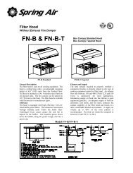
• Filter Hoods<br />
• Surface Fire Suppression<br />
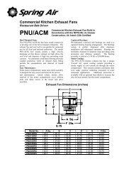
• Commercial Kitchen Exhaust Fans<br />
• Kitchen Enviro <strong>Systems</strong><br />
♦ KES - 100% Exhaust<br />
• Commercial Kitchen Supply Units<br />
• Compensating Hoods<br />
• Exhaust Fans<br />
• Supply Fans<br />
• Commercial Kitchen Control Panels<br />
• Variable Speed Exhaust/Supply <strong>Systems</strong><br />
Phone: 905-338-2999, FAX: 905-338-1079, e-mail info@springairsystems.com<br />
www.springairsystems.com