What is TRUFLOW? - Spring Air Systems Inc.
What is TRUFLOW? - Spring Air Systems Inc.
What is TRUFLOW? - Spring Air Systems Inc.

You also want an ePaper? Increase the reach of your titles
YUMPU automatically turns print PDFs into web optimized ePapers that Google loves.
Truflow<br />
Touchscreen<br />
Engineering<br />
Manual<br />
___________________________<br />
<strong>Spring</strong> <strong>Air</strong> <strong>Systems</strong> <strong>Inc</strong>., Oakville, Ontario<br />
Phone (866) 875-4505, Fax (905) 338-0179, info@springairsystems.com<br />
www.springairsystems.com<br />
December 2007
Engineering Manual<br />
Table of Contents<br />
Introduction 1<br />
<strong>What</strong> <strong>is</strong> Truflow? 3<br />
Why Use Truflow? 3<br />
How Many Hoods Can Be Connected to Each Exhaust Fan? 5<br />
Design Tips to Maximize Energy Savings 7<br />
How Does the Truflo Work? 8<br />
SV Supply Control 13<br />
SC Supply Control 15<br />
Activation Control Options 18<br />
Sequence of Operation 19<br />
Activating Kitchen One 19<br />
Summer Winter Operation 20<br />
Override 21<br />
Surface Fire Suppression 21<br />
Multiple Kitchen Operation 22<br />
Setting Goals 23<br />
Option Wireless Remote 24<br />
Appendix A Minimum Duct Velocity in the Building Code 25<br />
Appendix B Truflo Panel Model Number 26<br />
Appendix C Hood mounted Truflow Enclosure 27<br />
Appendix D Wall mounted Truflow Enclosure 28<br />
Appendix E Installation and Remote Wiring 29<br />
Appendix F Sample Specification 33<br />
Nov19
<strong>TRUFLOW</strong> Engineering Manual<br />
SEE WHAT YOU SAVE<br />
Introduction<br />
Prec<strong>is</strong>e, real-time measurement so you can effectively manage your team to reduce<br />
energy use.<br />
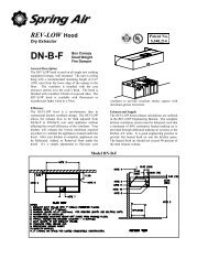
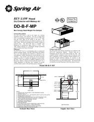
<strong>TRUFLOW</strong> DASHBOARD<br />
Figure 1<br />
Truflow <strong>is</strong> the most economical<br />
and efficient kitchen ventilation<br />
energy management system<br />
available.<br />
The average commercial kitchen<br />
exhaust system operates at 100%<br />
capacity for 12 to 18 hours per day,<br />
blowing thousands of wasted<br />
energy dollars out the roof!<br />
Truflow measures heat from the<br />
appliances and automatically<br />
adjusts fan speeds throughout the<br />
day, giving you the prec<strong>is</strong>e amount<br />
of exhaust at all times.<br />
Truflow monitors ventilation system efficiency relative to your utility costs, in real-time,<br />
so that you can manage your kitchen to take advantage of off peak times by turning down<br />
appliances. Setting an energy reduction goal reduces your utility costs even more!<br />
You have the ability to increase the exhaust volume to 100% at any time. Because you<br />
control it, overrides are kept to a minimum to maximize energy efficiency. The override<br />
system runs for an adjustable timed period of 15 minutes and can be activated at the hood<br />
or via a remote control.<br />
Truflow not only saves you money on energy expenses it can also help extend the life of<br />
your equipment by demanding exhaust only when it <strong>is</strong> really required. Truflow can be<br />
specified on new hoods or can be retrofitted on you ex<strong>is</strong>ting hoods. Since the panel can<br />
be hood mounted or wall mounted, it allows many convenient options of where to locate<br />
the panel and wireless remote unit. Truflow <strong>is</strong> internet accessible, so it <strong>is</strong> ideal for multiunit<br />
management.<br />
The <strong>TRUFLOW</strong> system reduces the amount of air exhausted from the kitchen to match<br />
the amount of cooking. As more appliances are used, the exhaust and supply volume<br />
increase, as less appliances are used the exhaust and supply volume decreases.<br />
<strong>Spring</strong> <strong>Air</strong> <strong>Systems</strong> <strong>TRUFLOW</strong> Engineering Manual December 2007 1
185<br />
Benefits:<br />
• Lower energy costs to boost profit<br />
• Improve kitchen air quality<br />
• Reduce kitchen fan no<strong>is</strong>e<br />
• Extend the life of your equipment<br />
• Internet accessible for remote management<br />
• Semi-automatic override to maximize energy efficiency<br />
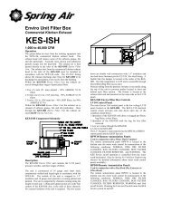
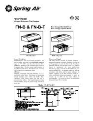
Exhaust Fan<br />
Roof Deck<br />
Exhaust Duct<br />
Fin<strong>is</strong>hed Ceiling<br />
J-COUPLE<br />
Exhaust Hood<br />
Touchscreen<br />
Fin<strong>is</strong>hed Floor<br />
Appliance Lineup<br />
<strong>TRUFLOW</strong> Setup screen<br />
Figure 3<br />
Typical <strong>TRUFLOW</strong> Kitchen<br />
Figure 2<br />
The <strong>TRUFLOW</strong> setup screen <strong>is</strong> shown in<br />
Figure 3 for the single kitchen above.<br />
The kitchen has one exhaust fan with one<br />
supply fan operating with a VSD<br />
(Variable Speed Drive). RSS (Remote<br />
Start Stop) has not been selected so the<br />
<strong>TRUFLOW</strong> will operate locally. KES<br />
has not been selected so the fan <strong>is</strong> a<br />
straight exhaust with no Kitchen Enviro<br />
System selected. In addition there <strong>is</strong> no<br />
WASH selected so there <strong>is</strong> no automatic<br />
wash type hood connected to th<strong>is</strong> kitchen.<br />
<strong>Spring</strong> <strong>Air</strong> <strong>Systems</strong> <strong>TRUFLOW</strong> Engineering Manual December 2007 2
<strong>What</strong> <strong>is</strong> <strong>TRUFLOW</strong>?<br />
The <strong>TRUFLOW</strong> Energy Management Controller has been designed to change kitchen<br />
exhaust forever. <strong>TRUFLOW</strong> will automatically reduce the exhaust and supply air into<br />
the kitchen whenever appliances are not used at full capacity. When the appliances are<br />
not used and the heat <strong>is</strong> turned down or off <strong>TRUFLOW</strong> automatically senses the<br />
reduction and decreases the amount of exhaust and supply to match exactly what’s<br />
happening under the exhaust hood. The <strong>TRUFLOW</strong> duct mounted J-Couple monitors the<br />
exhaust temperature, which fluctuates based on the amount of appliances operating under<br />
the exhaust hood. As the amount of cooking increases the exhaust duct temperature r<strong>is</strong>es<br />
and reaches an equilibrium temperature during each hour of the day. Th<strong>is</strong> equilibrium<br />
temperature represents a percentage of total cooking capacity. The 30% utilization<br />
temperature may be 80F. The 70% utilization temperature may be 105F. The duct<br />
temperature could reach as high as 150F and as low 75F depending on the following<br />
factors:<br />
• Kitchen room temperature<br />
• Total exhaust volume<br />
• BTU rating of each appliance<br />
• Total volume of makeup air<br />
• Temperature of makeup air<br />
• Where the makeup air <strong>is</strong> introduced back into the kitchen<br />
• Type of hood over the appliance<br />
<strong>TRUFLOW</strong> automatically modulates the exhaust and supply to suit the actual cooking<br />
operation at any given time during the cooking day.<br />
Why Use a <strong>TRUFLOW</strong>?<br />
Energy Savings up to 55% annually! Reduces operating cost.<br />
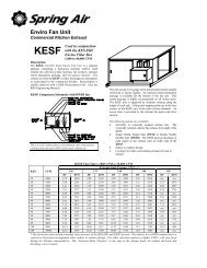
Let’s take a look at Chart No 1. The <strong>TRUFLOW</strong> does not lower the exhaust volume<br />
below 30% of the maximum operating exhaust. For the purpose of th<strong>is</strong> chart we add<br />
operating times below 30% into the 30% operating time.<br />
Appliance Operating Capacity<br />
% of full appliance load that kitchen <strong>is</strong> operating at<br />
Operating Time<br />
% of time that kitchen <strong>is</strong> operating at stated Appliance<br />
Operation Capacity<br />
Hours of 16 hour day Number of hours, out of a 16 hour day, equating to %<br />
shown in Operating Time<br />
Equivalent CFM<br />
Calculated as Total Exhaust CFM x (%Appliance<br />
Operating Capacity) x (%Operating Time)<br />
Based on 4500 CFM total exhaust volume from our example above, the chart <strong>is</strong> tabulated.<br />
<strong>Spring</strong> <strong>Air</strong> <strong>Systems</strong> <strong>TRUFLOW</strong> Engineering Manual December 2007 3
Typical Commercial Kitchen Operation with <strong>TRUFLOW</strong><br />
Appliance<br />
Operation<br />
Capacity (%)<br />
Operating Time<br />
(%)<br />
Hour of 16 hour<br />
day<br />
Equivalent<br />
CFM<br />
30 30 4.8 405<br />
40 10 1.6 180<br />
50 10 1.6 225<br />
60 5 0.8 135<br />
70 10 1.6 315<br />
80 5 0.8 180<br />
90 10 1.6 405<br />
100 20 3.2 900<br />
Equivalent Daily Exhaust Volume CFM<br />
2745 CFM<br />
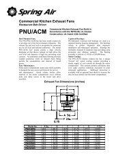
Semi Automatic Design<br />
<strong>TRUFLOW</strong> <strong>is</strong> a semi automatic design because of the manual OVERRIDE pushbutton.<br />
In the unlikely event that smoke does leak from the edge of the hood the operator simply<br />
pushes the OVERRIDE pushbutton to drive the exhaust volume to 100% for 15 minutes.<br />
After 15 minutes the exhaust automatically reverts back to temperature based control.<br />
(The 15 minutes override time <strong>is</strong> adjustable on the Touchscreen.) The smoke generated<br />
from appliances sometimes lags the duct temperature r<strong>is</strong>e because of the following:<br />
• Large quantities of greasy foods are tossed on the grille at one time.<br />
• A large tilting skillet or kettle <strong>is</strong> opened quickly or<br />
• A draft from a door or window opening.<br />
The <strong>TRUFLOW</strong> <strong>is</strong> comm<strong>is</strong>sioned by a <strong>Spring</strong> <strong>Air</strong> service<br />
technician to minimize these OVERRIDE events. The kitchen <strong>is</strong><br />
put into override by pressing the efficiency button on the<br />
Touchscreen Dashboard.<br />
Efficiency Button<br />
Figure 4<br />
From the Dashboard press the EFFICIENCY button to set the<br />
Truflow into override operation. The kitchen exhaust will operate<br />
at 100% volume for the time set on the override timer.<br />
To select the Override time, go to the System Control screen and<br />
press the O/R button. A second screen will open.<br />
The Override time <strong>is</strong> adjustable from the System Control screen by<br />
pressing the O/R button. The time <strong>is</strong> adjustable from 0 to 240<br />
minutes with a factory default of 15 minutes.<br />
Efficiency Button in Override<br />
Figure 5<br />
<strong>Spring</strong> <strong>Air</strong> <strong>Systems</strong> <strong>TRUFLOW</strong> Engineering Manual December 2007 4
How many hoods can be connected to each exhaust fan?<br />
Truflow Setup Screen<br />
Figure 6<br />
Each <strong>TRUFLOW</strong> Touchscreen <strong>is</strong><br />
capable of operating five independent<br />
kitchens, six exhausts and/or supply<br />
fans with up to 10 commercial<br />
kitchen hoods per exhaust fan. The<br />
number of exhaust fans <strong>is</strong> determined<br />
by the operational requirements of the<br />
kitchen appliances under each hood.<br />
When three hoods and two exhaust<br />
fans are connected as one kitchen any<br />
change in appliance usage under any<br />
of the three hoods will result in<br />
increasing the volume of the two<br />
exhaust fans. The optimum Truflow<br />
method to maximize savings <strong>is</strong> to<br />
operate the <strong>TRUFLOW</strong> Touchscreen<br />
with two kitchens cons<strong>is</strong>ting of one<br />
exhaust fan and one hood, and one exhaust fan and two hoods. The two kitchens operate<br />
completely independently supplying a single 4-20 milliamp signal to one makeup air unit.<br />
Truflow Setup Screen –Two Kitchens<br />
– two exhaust 4-20 milliamp supply signal<br />
Figure 7<br />
The schematic below shows a<br />
restaurant with one exhaust fan with<br />
one hood and one exhaust fan with two<br />
hoods. Th<strong>is</strong> should be operated by the<br />
Truflow as two kitchens. Kitchen One<br />
cons<strong>is</strong>ts of one exhaust fan and one<br />
hood. Kitchen Two cons<strong>is</strong>ts of one<br />
exhaust fan and two exhaust hoods.<br />
The restaurant could have one or two<br />
makeup air units. One makeup air unit<br />
could be controlled by both kitchens or<br />
each kitchen could control a separate<br />
makeup air unit. Energy savings with<br />
one or two makeup air units would be<br />
similar.<br />
<strong>Spring</strong> <strong>Air</strong> <strong>Systems</strong> <strong>TRUFLOW</strong> Engineering Manual December 2007 5
185<br />
185<br />
Exhaust Fan<br />
Exhaust Fan<br />
Roof Deck<br />
Roof Deck<br />
Exhaust Duct<br />
Exhaust Duct<br />
Fin<strong>is</strong>hed Ceiling<br />
Fin<strong>is</strong>hed Ceiling<br />
Exhaust Hood<br />
Exhaust Hood #1<br />
Exhaust Hood #2<br />
SYSTEMS ONE: ONE EXHAUST FAN ONE HOOD<br />
SYSTEM TWO: ONE EXHAUST FAN/TWO HOODS<br />
Kitchen 1: One hood and one exhaust fan, Kitchen two: Two hoods with<br />
one exhaust fan. Both Kitchens control a single makeup air unit.<br />
Figure 8<br />
<strong>TRUFLOW</strong> System Control Screen for Operation: Two<br />
Kitchens, Two exhausts, Two supply 4-20 milliamp signals<br />
Figure 9<br />
<strong>Spring</strong> <strong>Air</strong> <strong>Systems</strong> <strong>TRUFLOW</strong> Engineering Manual December 2007 6
185<br />
185<br />
185<br />
185<br />
SV<br />
°F<br />
C1<br />
C2<br />
AL 1 1 1 0<br />
AL 2<br />
SEL<br />
SPR I NG AI R<br />
SUMMER /WINTE R C AN O PY L I GH TS<br />
EX HAU ST<br />
OCC UPIED/UNOCCUPIED<br />
SU PPLY<br />
OPE RA TION<br />
TRU-FLO VARI ABLE CONTROL<br />
HI<br />
PUSHTO OVERIDE<br />
Exhaust Fan<br />
Exhaust Fan<br />
Exhaust Fan<br />
Exhaust Fan<br />
Roof Deck<br />
Roof Deck<br />
Roof Deck<br />
Roof Deck<br />
Exhaust Duct<br />
Exhaust Duct<br />
Exhaust Duct<br />
Exhaust Duct<br />
Exhaust Hood #1<br />
Exhaust Hood #2<br />
Exhaust Hood #3<br />
Exhaust Hood #4<br />
SYSTEM ONE: 1 EXHAUST, ONE HOOD<br />
SYSTEM TWO: 1 EXHAUST, ONE HOOD<br />
SYSTEM THREE: 1 EXHAUST, ONE HOOD<br />
SYSTEM FOUR: 1 EXHAUST, ONE HOOD<br />
Four Kitchens with one hood and one exhaust fan each. One 4-20 milliamp signal <strong>is</strong><br />
send to one single makeup air unit based on the combined exhaust volume.<br />
Figure 10<br />
<strong>TRUFLOW</strong> Setup screen for Operation: Four Kitchens,<br />
Four exhausts, Four supply 4-20 milliamp signals<br />
Figure 11<br />
Design Tips to Maximize Energy Savings<br />
• Connect each hood to an exhaust fan whenever possible or as the budget allows.<br />
• For each Truflow Touchscreen use as many sub Kitchens as possible for each<br />
individual hood and exhaust fan operation.<br />
<strong>Spring</strong> <strong>Air</strong> <strong>Systems</strong> <strong>TRUFLOW</strong> Engineering Manual December 2007 7
How does the <strong>TRUFLOW</strong> Work?<br />
The <strong>TRUFLOW</strong> cons<strong>is</strong>ts of three primary components:<br />
1. J-couple.<br />
2. Touchscreen<br />
3. Variable Speed Drives<br />
1. J-COUPLE<br />
The J-couple <strong>is</strong> mounted in the center of each exhaust hood duct collar. The J-couple<br />
threads into a UL/ULC l<strong>is</strong>ted hood penetration fitting. The J-couple wiring <strong>is</strong> terminated<br />
in a factory supplied J-Box.<br />
J-couple Mini-Clip connector to the Truflo panel<br />
UL/ULC duct penetration fitting<br />
J-box<br />
Exhaust duct collar<br />
J-couple<br />
Exhaust Hood<br />
2. TOUCHSCREEN<br />
J-Couple hood duct collar mounting<br />
Figure 12<br />
Touchscreen Dashboard<br />
Figure 13<br />
The Touchscreen includes five functional screens: Dashboard, System Control, Alarm<br />
Status, Reports and Setup & Diagnostics.<br />
a. Dashboard<br />
<strong>Spring</strong> <strong>Air</strong> <strong>Systems</strong> <strong>TRUFLOW</strong> Engineering Manual December 2007 8
• Graph represents energy use throughout<br />
day<br />
• Energy consumption measured against<br />
reduction goal<br />
• Dashboard tells kitchen staff whether<br />
system exceeding goal or not.<br />
• Exhaust CFM, duct and outdoor<br />
temperature d<strong>is</strong>played<br />
• Outdoor temperature measurement<br />
allows for real-time energy savings<br />
reports directly from TruFlow!<br />
Touchscreen Dashboard<br />
Figure 14<br />
b. System Control<br />
• D<strong>is</strong>plays components of all exhaust<br />
systems controlled by TruFlow<br />
– Hood lights<br />
– Fan on/off<br />
– Summer/winter switch<br />
– Override<br />
c. Alarm Status<br />
Touchscreen System Control<br />
Figure 15<br />
• Alarm conditions d<strong>is</strong>played for all<br />
systems controlled by TruFlow<br />
• Touch single bell icon to clear selected<br />
alarm<br />
• Touch multi-bell icon to clear all alarms<br />
• Th<strong>is</strong> action does not FIX the problem it<br />
simply records that an alarm or alarms<br />
have been acknowledged.<br />
• Service Company must still be called!<br />
Touchscreen Alarm Status<br />
Figure 16<br />
<strong>Spring</strong> <strong>Air</strong> <strong>Systems</strong> <strong>TRUFLOW</strong> Engineering Manual December 2007 9
d. Alarm Condition<br />
• On alarm, d<strong>is</strong>play changes to alarm<br />
with optional audible alert<br />
• Touchscreen to go to Alarm Status<br />
Screen<br />
• Touching screen records action in<br />
event log<br />
e. Reports<br />
Alarm Condition Screen<br />
Figure 17<br />
• TruFlow can record a full year of data<br />
• Standard reports provided<br />
• Can create custom reports depending<br />
on needs of user<br />
• % Time Exceeding Goal <strong>is</strong> a key<br />
energy management report<br />
f. Setup & Diagnostics<br />
Touchscreen Reports<br />
Figure 18<br />
• Main system setup d<strong>is</strong>play allows<br />
entry of reduction goal, primary<br />
message center text and company or<br />
restaurant name<br />
• Power of TruFlow lies in the setting of<br />
an energy reduction goal<br />
• Goal represents a target % reduction of<br />
past utility costs (hourly or monthly<br />
rate)<br />
Touchscreen Setup<br />
Figure 19<br />
<strong>Spring</strong> <strong>Air</strong> <strong>Systems</strong> <strong>TRUFLOW</strong> Engineering Manual December 2007 10
• Goal can be reset at any time to maximize energy efficiency and savings!<br />
• Gas and electricity costs can be entered at any time as monthly or hourly rates<br />
• Measure gas in joules or therms by selecting Imperial or Metric Units<br />
• Set daily or weekly operating times<br />
• Permits<br />
• Comprehensive service screen to quickly diagnose problems<br />
• Can access via Internet for remote service by <strong>Spring</strong> <strong>Air</strong> directly or Authorized<br />
Service Technician<br />
3. VARIBLE SPEED DRIVES<br />
The variable speed drives for the exhaust and/or supply fan can be located in a<br />
stainless steel enclosure adjacent to the Touchscreen panel or anywhere else in the<br />
building.<br />
• When direct gas fire unit <strong>is</strong> part of <strong>TRUFLOW</strong> the supply drive can be located<br />
in the makeup air unit control panel or with the exhaust fan drive(s) (SV<br />
Type)<br />
• When a SFA-IGO unit <strong>is</strong> part of <strong>TRUFLOW</strong>, a supply drive <strong>is</strong> not required.<br />
The Touchscreen panel sends a 4-20milliamp signal through a CAT5 cable to<br />
the makeup air unit modulating bypass damper. (SC Type)<br />
Two exhaust drives and one supply drive connected to the Touchscreen panel<br />
Figure 20<br />
A CAT5 cable <strong>is</strong> connected to each drive in series from the Touchscreen panel. The<br />
first cable connects from the Touchscreen to the first drive “Y” connector. The 2 nd<br />
drive cable connects from the first drive “Y” connector to the 2 nd drive “Y”<br />
connector. Each drive <strong>is</strong> connected in series. When the Touchscreen <strong>is</strong> initially<br />
activated the communication software starts all the exhaust and/or supply drive at<br />
100% capacity for 10 seconds for each kitchen. After the initial 10 seconds the<br />
exhaust and/or supply drives ramp up and down depending on the signal from the J-<br />
couple(s). As the exhaust volume increases and decreases, the supply volume<br />
increases and decreases in un<strong>is</strong>on to maximize energy savings. The supply unit<br />
motorized damper end switch can also be interlocked to the Touchscreen such that the<br />
end switch must close to start the supply fan drive operation.<br />
<strong>Spring</strong> <strong>Air</strong> <strong>Systems</strong> <strong>TRUFLOW</strong> Engineering Manual December 2007 11
The drive changes the AC<br />
to the exhaust motor between 18Hz<br />
frequency<br />
and 60Hz.<br />
Variable Speed Drive<br />
Figure 21<br />
Variable Speed Drive Field Wiring<br />
Figure 22<br />
<strong>Spring</strong> <strong>Air</strong> <strong>Systems</strong> <strong>TRUFLOW</strong> Engineering Manual December 2007 12
SV Supply Control<br />
<strong>TRUFLOW</strong> Operation with SV Control for the following applications:<br />
• SAT direct gas fired supply units<br />
• Other direct gas fired supply units with unit mounted variable speed drive VSD<br />
• Supply units with electric heating, hot water heating, or no heating or cooling<br />
The Touchscreen receives a signal from the duct mounted J-couple that controls the<br />
exhaust motor VSD. The exhaust motor variable speed drive slows or speeds up the<br />
exhaust fan motor to maintain the required exhaust volume to match the amount of<br />
cooking. Simultaneously the Truflow controls the <strong>Spring</strong> <strong>Air</strong> SAT supply fan motor or<br />
other supply fan motors supplied by others. The supply variable speed drive changes the<br />
frequency of the supply fan motor to modulate the supply air into the kitchen space in<br />
proportion to the exhaust air volume.<br />
Exhaust<br />
Fan<br />
SUPPLY FAN<br />
CAT5 Variable Speed<br />
drive signal to motor<br />
CAT5 Variable Speed<br />
Drive signal to motor<br />
J-Couple<br />
Kitchen Hood<br />
SV- Supply Volume Control with Variable Speed Supply Drive<br />
Figure 23<br />
The lowest possible exhaust volume <strong>is</strong> 30% of the maximum to meet the ex<strong>is</strong>ting code<br />
and to ensure that the products of combustion are always completely exhausted.<br />
<strong>Spring</strong> <strong>Air</strong> <strong>Systems</strong> <strong>TRUFLOW</strong> Engineering Manual December 2007 13
185<br />
185<br />
100%<br />
<strong>Spring</strong> <strong>Air</strong> SAT (Direct Gas Fired Makeup <strong>Air</strong> Unit)<br />
J-couple<br />
Exhaust Hood<br />
<strong>TRUFLOW</strong><br />
TOUCHSCREEN<br />
<strong>TRUFLOW</strong> System operating at 100% with SAT direct gas fired makeup with SV control<br />
Figure 24<br />
30%<br />
<strong>Spring</strong> <strong>Air</strong> SAT (Direct Gas Fired Makeup <strong>Air</strong> Unit)<br />
J-couple<br />
Exhaust Hood<br />
<strong>TRUFLOW</strong><br />
TOUCHSCREEN<br />
<strong>TRUFLOW</strong> operating at 30% with SAT direct gas fired makeup with SV control<br />
Figure 25<br />
<strong>Spring</strong> <strong>Air</strong> <strong>Systems</strong> <strong>TRUFLOW</strong> Engineering Manual December 2007 14
<strong>TRUFLOW</strong> – One Kitchen – Two exhaust fans – One supply fan – Six hoods<br />
Figure 26<br />
SC Supply Control<br />
<strong>TRUFLOW</strong> Operation with SC Control for the following applications:<br />
• SFT-IGO fresh air unit with heating or DX cooling<br />
• A 4-20 milliamp signal to Building Management System to control fresh air with<br />
HVAC bypass dampers<br />
• A 4-20 milliamp signal to a fresh air makeup air unit to modulate fresh air/return<br />
air bypass damper(s)<br />
Truflow receives signals from the J-couple and transmits a signal along a CAT5 cable to<br />
the exhaust motor VSD. The exhaust motor variable speed drive slows or speeds up the<br />
exhaust fan to maintain the required exhaust volume depending on the amount of<br />
cooking. At the same time, Truflow sends a 4-20 milliamp signal to the <strong>Spring</strong> <strong>Air</strong> SFT<br />
supply unit modulating Bypass <strong>Air</strong> damper. Th<strong>is</strong> bypass damper modulates to bypass<br />
fresh air from the supply air d<strong>is</strong>charge back to the SFT fan section.<br />
The lowest possible exhaust volume <strong>is</strong> 30% of the maximum to meet the ex<strong>is</strong>ting code<br />
and ensure that the products of combustion are always adequately exhausted.<br />
<strong>Spring</strong> <strong>Air</strong> <strong>Systems</strong> <strong>TRUFLOW</strong> Engineering Manual December 2007 15
Exhaust<br />
Fan<br />
CAT5 Variable Speed<br />
drive signal to motor<br />
4-20 milliamp Signal to<br />
Bypass Damper Motor<br />
J-Couple<br />
Signal<br />
Kitchen Hood<br />
SV- Supply Volume Control with Variable Speed Supply Drive<br />
Figure 27<br />
Truflow – One exhaust fan – One 4-20 milliamp supply signal – Three hoods<br />
Figure 28<br />
<strong>Spring</strong> <strong>Air</strong> <strong>Systems</strong> <strong>TRUFLOW</strong> Engineering Manual December 2007 16
185<br />
185<br />
100%<br />
<strong>Spring</strong> <strong>Air</strong> SFT<br />
Blend <strong>Air</strong> Channel<br />
J-couple<br />
Exhaust Hood<br />
<strong>TRUFLOW</strong><br />
<strong>TRUFLOW</strong> operating at 100%. No Bypass required on <strong>Spring</strong> <strong>Air</strong> SFT<br />
Figure 29<br />
30%<br />
<strong>Spring</strong> <strong>Air</strong> SFT<br />
BYPASS <strong>Air</strong><br />
J-couple<br />
Exhaust Hood<br />
<strong>TRUFLOW</strong><br />
<strong>TRUFLOW</strong> operating at 30%. Notice the bypass air below the on <strong>Spring</strong> <strong>Air</strong> SFA<br />
Figure 30<br />
<strong>Spring</strong> <strong>Air</strong> <strong>Systems</strong> <strong>TRUFLOW</strong> Engineering Manual December 2007 17
Activation Control Options<br />
There are four separate <strong>TRUFLOW</strong> Operation Control options: Manual Control at the<br />
panel, Automatic Control using panel auto function, Remote Start/Stop Control with dry<br />
contact, and BACnet or LON control directly to the <strong>TRUFLOW</strong> PLC.<br />
1. Manual Control:<br />
Press the System Control button<br />
to switch to the screen<br />
Press the Hand button to switch<br />
to manual mode.<br />
Each kitchen <strong>is</strong> turned on by<br />
pressing the Fan button. Active<br />
button has white border.<br />
When the fan <strong>is</strong> on the fan<br />
graphic icon <strong>is</strong> moving.<br />
System Control screen<br />
Figure 31<br />
Pressing the button again turns<br />
off the kitchen operation.<br />
2. Automatic Control:<br />
Press the Setup button to<br />
change to the System Setup<br />
screen<br />
Press the Fan Time button to<br />
change to the Kitchen<br />
Operation screen. Select the<br />
Operation time or hours for each day<br />
of the week.<br />
Fan Time screen<br />
Figure 32<br />
Go to the System Control<br />
screen and press the Hand<br />
button off. The white border<br />
surrounding the button will d<strong>is</strong>appear<br />
and the operation <strong>is</strong> now in automatic<br />
mode. The kitchen on and off times<br />
will follow the time set on the Fan<br />
Time screen.<br />
<strong>Spring</strong> <strong>Air</strong> <strong>Systems</strong> <strong>TRUFLOW</strong> Engineering Manual December 2007 18
3. Remote Start/Stop:<br />
Setup screen RSS checked<br />
Figure 33<br />
Press the Setup button twice<br />
quickly to change to the<br />
secondary System Setup<br />
screen.<br />
Press the System<br />
Setup bar once and<br />
then Press the RSS<br />
button. The automatic mode as<br />
described above <strong>is</strong> d<strong>is</strong>abled and the<br />
RSS (Remote Start/Stop) function <strong>is</strong><br />
enabled. Closing a dry contact across<br />
terminals C+L will activate kitchen<br />
one. Closing a dry contact across<br />
terminals C2+CL will activate kitchen<br />
two…etc.<br />
4. BACnet or LON:<br />
The <strong>TRUFLOW</strong> panel can be operated directly from a BACnet or LON building<br />
management system. Connecting to the PLC through a RS234 connection will allow<br />
each kitchen to be operated from the Building Management System. The BMS can also<br />
read all information for the drives and panels. Truflow <strong>is</strong> LON compatible. An optional<br />
intermediate device can be supplied by <strong>Spring</strong> <strong>Air</strong> between the PLC and LON system to<br />
convert the various Truflow input and outputs to be recognized by the LON system.<br />
Sequence of Operation<br />
There are four separate <strong>TRUFLOW</strong> Operation Control options: Manual Control at the<br />
panel, Automatic Control using panel auto function, Remote Start/Stop Control with dry<br />
contact, and BACnet or LON control directly to the <strong>TRUFLOW</strong> PLC. See the section<br />
above for description of each method to activate the Truflow panel.<br />
At the start of the cooking day: Each kitchen connected to the Truflow panel <strong>is</strong> activated<br />
either manually, automatically, remotely or from a BACnet or LON.<br />
1. Activating Kitchen One<br />
All exhaust fans and supply fans connected to Kitchen One drive to 100% volume for 10<br />
seconds. After the initial 10 seconds each exhaust and supply return to normal mode.<br />
Normal mode <strong>is</strong> the exhaust and supply volume based on the number of appliances<br />
activated under the hoods served by the exhaust fans for Kitchen One. As more<br />
appliances are turned on or turned up, the hood duct J-couples sense the rate of change of<br />
duct temperature sending a signal to the Truflow to adjust the speed of the exhaust and<br />
supply fan motors.<br />
<strong>Spring</strong> <strong>Air</strong> <strong>Systems</strong> <strong>TRUFLOW</strong> Engineering Manual December 2007 19
Once the kitchen <strong>is</strong> turned on the dashboard graph <strong>is</strong> activated. The graph<br />
measures systems efficiency vs. seconds of operation.<br />
The system efficiency measures the<br />
operating efficiency of the kitchen as<br />
compared to the energy reduction goal<br />
set by kitchen management.<br />
In the example the real time<br />
operating efficiency <strong>is</strong> 75%.<br />
Th<strong>is</strong> means the kitchen <strong>is</strong><br />
operating at 75% of the energy savings<br />
goal.<br />
The Exhaust CFM <strong>is</strong> the<br />
actual total exhaust for<br />
Kitchen One.<br />
Dashboard Efficiency Graph<br />
Figure 34<br />
The Outside Temp <strong>is</strong> the actual outside temperature. Th<strong>is</strong> value <strong>is</strong> used to<br />
calculate the BTU’s of heating or cooling required for the kitchen. The BTU’s<br />
are converted to actual dollar cost and can be viewed from the Report screen.<br />
The light bulb turns the canopy light on and off.<br />
Press System Control to view<br />
other control options. Kitchen<br />
1 <strong>is</strong> the top row of symbols on<br />
the screen.<br />
The rotating fan icon indicates<br />
that the system <strong>is</strong> active.<br />
The light bulb can also be used<br />
to turn the canopy lights off<br />
and for the kitchen.<br />
System Control Screen<br />
Figure 35<br />
2. Summer/Winter<br />
The summer/winter symbol operation <strong>is</strong> connected to a Truflow dry contact across<br />
terminals 11+12. Pressing the icon on the System Control screen above changes the<br />
kitchen operation from summer to winter and back again.<br />
<strong>Spring</strong> <strong>Air</strong> <strong>Systems</strong> <strong>TRUFLOW</strong> Engineering Manual December 2007 20
Winter Operation: When the winter icon <strong>is</strong> d<strong>is</strong>played a Truflow dry contact closes.<br />
The icon <strong>is</strong> used in winter mode to turn off the (optional) makeup air cooling<br />
system and turn on the makeup air heating system. The Reports are now<br />
calculating the cost of heating the fresh air from the outside temperature to the<br />
room temperature or accumulating th<strong>is</strong> cost in chart form.<br />
Summer Operation: When the summer icon <strong>is</strong> indicated the Truflow dry contacts are<br />
open. The summer icon <strong>is</strong> used to turn off the makeup air heating system and<br />
activate the (optional) makeup air cooling system if it <strong>is</strong> present. The Reports are<br />
now calculating the electrical cost to operate a DX air conditioning system based<br />
on the difference between the outside dry bulb temperature and the inside dry bulb room<br />
temperature. The accumulated results are presented on the Report screen. When the A/C<br />
button located on the Setup/Goals screen <strong>is</strong> not selected the cost of summer kitchen<br />
cooling <strong>is</strong> not calculated and accumulated.<br />
3. Override<br />
Override Adjustment on System Control<br />
Figure 36<br />
Each Kitchen can be put into<br />
Override mode by pressing the<br />
EFFICIENCY button on the<br />
Dashboard of the individual<br />
kitchens. The factory override time <strong>is</strong><br />
set at 15 minutes.<br />
The override time can be<br />
adjusted from the System Control<br />
screen above. Pressing the O/R button<br />
to open a sub screen where the length of<br />
the override (in minutes) can be selected.<br />
4. Surface Fire Suppression<br />
The surface fire suppression <strong>is</strong> interlocked to th<strong>is</strong> panel from a micro switch located in<br />
the cylinder head of the fire suppression system. In the event of surface fire activation<br />
the micro switch closes across Truflow terminals B+L and the Truflow exhaust fans will<br />
continue to operate, the supply fans will shut off, and a 120V signal <strong>is</strong> sent to the shunt<br />
trip connected to the appliances under the hood with the activated surface fire<br />
suppression system. A panel alarm will annunciate. Press the screen and the alarm<br />
message will scroll across the bottom of the Truflow screen.<br />
<strong>Spring</strong> <strong>Air</strong> <strong>Systems</strong> <strong>TRUFLOW</strong> Engineering Manual December 2007 21
5. Multiple Kitchen Operation<br />
Press the Setup icon to switch to<br />
the First Setup screen.<br />
First Setup screen<br />
Figure 37<br />
Press Setup icon again on the<br />
first second setup screen to<br />
switch to the Second Setup screen.<br />
Second Setup screen<br />
Figure 38<br />
System Setup screen<br />
Figure 39<br />
Press the System Setup bar above to<br />
change to the screen on the left. First<br />
select the number of systems or<br />
Kitchens. Now select the number of<br />
exhaust fans for each system and then<br />
select whether the supply control will<br />
be by VSD or 4-20 milliamps. A<br />
unique name can be selected for each<br />
kitchen by touching the kitchen name.<br />
An on the system keyboard opens to<br />
allow the new name to be entered and<br />
stored in the Truflow.<br />
<strong>Spring</strong> <strong>Air</strong> <strong>Systems</strong> <strong>TRUFLOW</strong> Engineering Manual December 2007 22
Press the System Control icon to<br />
change screens. The System<br />
Control screen will d<strong>is</strong>play all four<br />
kitchens entered on the Setup screen.<br />
Each kitchen can be individually<br />
controlled from th<strong>is</strong> screen.<br />
Multiple System Control screen<br />
Figure 40<br />
Pressing the Dashboard icon<br />
shows the operation of each<br />
individual kitchen. Pressing the<br />
Kitchen name, Efficiency, or Exhaust<br />
CFM buttons will change the screen to the<br />
efficiency graph for the kitchen selected.<br />
6. Setting Goals<br />
Multiple Dashboard screen<br />
Figure 41<br />
Select the Setup icon to change<br />
the screen to the main setup<br />
screen. Th<strong>is</strong> screen would normally be<br />
locked and a password <strong>is</strong> required to see<br />
the next setup screen information as seen<br />
to the left.<br />
First Setup screen<br />
Figure 42<br />
<strong>Spring</strong> <strong>Air</strong> <strong>Systems</strong> <strong>TRUFLOW</strong> Engineering Manual December 2007 23
Reduction Goal Setup screen<br />
Figure 43<br />
Select the Dollar icon to change to<br />
the Energy Reduction Goal setup<br />
screen.<br />
The Energy Reduction Goal value <strong>is</strong> the<br />
percentage energy savings that the operator<br />
wants to achieve during normal operation of<br />
the kitchens. To save 20% annually, enter<br />
the number 20. The higher the percentage<br />
entered the more aggressive the energy<br />
savings goal. Next select the units imperial<br />
or metric. Enter the cost of gas in $/BTU’s.<br />
Enter the cost of electricity in $/KWH.<br />
Check Demand Electrical if the utility<br />
company has graduated billing throughout<br />
the day. Follow screen prompt to enter the demand cost of electricity and the time it<br />
takes effect. Finally select the A/C button if the kitchen <strong>is</strong> air conditioned with DX<br />
(Direct Expansion) cooling. If the kitchen <strong>is</strong> not air conditioned the summer energy cost<br />
will be only the cost of the exhaust and supply fan motors.<br />
Press the Dashboard icon to return to normal operation. The goal setting number shifts<br />
the ax<strong>is</strong> of the efficiency curve on the dashboard. A higher goal means the operation will<br />
run in the RED, or under 100% efficiency more often unless the kitchen operators are<br />
diligent at turning down or turning off appliances that are not in use. When the efficiency<br />
graph <strong>is</strong> in the RED the operator must glance at the appliances and shut off or turn down<br />
any that are not in use. If all the appliances are being used to cook products then the<br />
operation <strong>is</strong> profitable. The equipment <strong>is</strong> being properly utilized for the operation and it<br />
<strong>is</strong> acceptable for the efficiency graph to be in the RED. “SEE YOUR SAVINGS” by<br />
using the graph.<br />
7. Optional Wireless Remote<br />
1. The standard <strong>TRUFLOW</strong> system can be supplied with a wireless remote to<br />
provide a remote override button from another location in the kitchen.<br />
2. Truflow panel Kitchen One <strong>is</strong> on:<br />
a) Press the wireless remote once and the exhaust immediately<br />
ramps to 100% for approximately 15 minutes.<br />
b) Press the wireless remote again and hold for two (2) seconds<br />
the exhaust returns to normal operation.<br />
3. Truflow panel Kitchen One <strong>is</strong> off:<br />
c) Press the wireless remote once and the exhaust immediately<br />
ramps to 100% for approximately 15 minutes.<br />
d) Press the wireless remote again and hold for two (2) seconds and the exhaust<br />
and supply return to normal operation.<br />
e) Press the wireless remote again and hold for four (4) seconds and the exhaust<br />
and supply shut off.<br />
<strong>Spring</strong> <strong>Air</strong> <strong>Systems</strong> <strong>TRUFLOW</strong> Engineering Manual December 2007 24
APPENDIX A.<br />
Minimum duct velocity in the Building Code<br />
The National Fire Protection Association code, NFPA-96 2001, changed to provide for a<br />
reduction of the exhaust air from a commercial kitchen during low demand periods. The<br />
minimum duct velocity in the NFPA-96 2001 has been reduced from 1500 fpm to 500<br />
fpm. In addition the International Building Code, IBC, was changed in 2003 to allow for<br />
the reduction in exhaust from a commercial kitchen during low demand periods. Local<br />
building and fire departments have these codes in their possession and will have no<br />
reason not to allow a <strong>TRUFLOW</strong> installation anywhere in North America.<br />
International Mechanical Code. 2003<br />
Section 507 Commercial Kitchen Hoods<br />
507.1 General<br />
Exceptions:<br />
3. Net exhaust volumes for hoods shall be permitted<br />
to be reduced during no-load cooking conditions,<br />
where engineered or l<strong>is</strong>ted multi-speed or variablespeed<br />
controls automatically operate the exhaust<br />
system to maintain capture and removal of cooking<br />
effluents as required by th<strong>is</strong> section.<br />
NFPA-96, 2001<br />
8.2 <strong>Air</strong>flow<br />
8.2.1 <strong>Air</strong> Velocity<br />
8.2.1.1 The air velocity through any duct shall be<br />
not less than 152.1m/min (500 ft/min)<br />
Sizing the Exhaust Ductwork<br />
We recommend that the engineer size the exhaust ductwork for 1670 fpm velocity. The<br />
NPFA-96 code allows for a reduction in duct velocity to 500 fpm. By sizing the<br />
ductwork at 1670 for 100%, exhaust and duct velocity will be 500 fpm at 30% exhaust<br />
volume.<br />
<strong>Spring</strong> <strong>Air</strong> <strong>Systems</strong> <strong>TRUFLOW</strong> Engineering Manual December 2007 25
APPENDIX B.<br />
<strong>TRUFLOW</strong> Panel Model Number<br />
RPD-P 1 1 A W 2 TF 1 SC<br />
1- Total number of exhaust fan (Up to five exhaust fans)<br />
1- Total number of supply fans (one per kitchen)<br />
A- Standard Panel<br />
B- BACnet or LON panel.<br />
W- Wall mounted panel<br />
H – Hood mounted panel<br />
2- Total number of kitchens<br />
TF- <strong>TRUFLOW</strong> Variable Speed<br />
1- Total number of exhaust hood duct collars (10 per kitchen)<br />
SC- Supply 4-20 milliamps<br />
SV- Supply VSD<br />
<strong>Spring</strong> <strong>Air</strong> <strong>Systems</strong> <strong>TRUFLOW</strong> Engineering Manual December 2007 26
APPENDIX C.<br />
Truflow stainless steel enclosures dimensions<br />
Hood mounted.<br />
<strong>TRUFLOW</strong> enclosure, hood mounted<br />
Figure 45<br />
<strong>Spring</strong> <strong>Air</strong> <strong>Systems</strong> <strong>TRUFLOW</strong> Engineering Manual December 2007 27
APPENDIX D.<br />
Truflow stainless steel enclosures dimensions<br />
Wall Mounted.<br />
<strong>TRUFLOW</strong> enclosure wall mounted<br />
Figure 46<br />
<strong>Spring</strong> <strong>Air</strong> <strong>Systems</strong> <strong>TRUFLOW</strong> Engineering Manual December 2007 28
APPENDIX E.<br />
Remote Wiring<br />
<strong>TRUFLOW</strong> Control panel wiring schematic One Kitchen<br />
Figure 47<br />
<strong>Spring</strong> <strong>Air</strong> <strong>Systems</strong> <strong>TRUFLOW</strong> Engineering Manual December 2007 29
<strong>TRUFLOW</strong> Control panel wiring schematic Two Kitchens<br />
Figure 48<br />
<strong>Spring</strong> <strong>Air</strong> <strong>Systems</strong> <strong>TRUFLOW</strong> Engineering Manual December 2007 30
<strong>TRUFLOW</strong> Control panel wiring schematic Three Kitchens<br />
Figure 49<br />
<strong>Spring</strong> <strong>Air</strong> <strong>Systems</strong> <strong>TRUFLOW</strong> Engineering Manual December 2007 31
<strong>TRUFLOW</strong> Control panel wiring schematic Four Kitchens<br />
Figure 50<br />
<strong>Spring</strong> <strong>Air</strong> <strong>Systems</strong> <strong>TRUFLOW</strong> Engineering Manual December 2007 32
APPENDIX F.<br />
Sample Specification<br />
The commercial kitchen energy management controller shall be a <strong>Spring</strong> <strong>Air</strong> <strong>Systems</strong> TruFlow-<br />
EMC model RPD-PXX-AH-TF-X-WV. The Truflow shall provide semi automatic variable speed<br />
operation 24 hour/day for the commercial kitchen ventilation system. The panel shall be CSA<br />
certified and supplied in an 18GA stainless steel enclosure with No. 4 fin<strong>is</strong>h for hood, surface<br />
wall, or recessed wall mounting. The Truflow NEMA4x Touchscreen operates in conjunction with<br />
an integral PLC to provide daily reduction of the commercial kitchen exhaust and supply, and<br />
real-time temperature based control of energy target goal management. Truflow has optional<br />
LON, BACnet or MODbus interfaces to the Building Automation <strong>Systems</strong> (BAS). Each Truflow<br />
panel shall be internet accessible with a secure password through the local IP address for each<br />
location. The internet operator shall access the Touchscreen panel and view, control, or execute<br />
all functions available to the local kitchen operator.<br />
The Touchscreen controller shall be complete with Dashboard, System Control, Alarm Status,<br />
Reports and Setup & Diagnostic screens.<br />
The Dashboard screen shall graph energy usage throughout the day measuring energy<br />
consumption against user-set goals. The Dashboard screen also d<strong>is</strong>plays exhaust volume,<br />
outdoor temperature, hood lights, and % of goal reduction that <strong>is</strong> achieved each minute of the<br />
day.<br />
The System Control screen d<strong>is</strong>plays all components of the kitchen ventilation system: hood<br />
lights, fan on/off, summer/winter switch, and overrides. Each Truflow <strong>is</strong> capable of providing five<br />
independent systems with a maximum of five exhaust variable speed drives and one supply<br />
variable speed drive and/or a 4-20 milliamp output for each system.<br />
The Alarm Status Screen indicates and logs all alarm events which include: high temperature<br />
operation, electrical faults, J-couple faults, and supply drive communication error/failure and<br />
exhaust/supply drive communication error/failure.<br />
The Report screen provides fingertip selection of reports for Year to Date cost of gas, Year to<br />
Date cost of electricity, Daily cost of Utilities, % time exceeding goal and % time in override.<br />
The System Setup screen <strong>is</strong> accessible by the admin<strong>is</strong>trator with a secure password to customize<br />
the screen to the user, enter reduction goal, operating times, utility costs and provides system<br />
diagnostics.<br />
The Truflow modulates the exhaust and supply volume through variable speed exhaust and<br />
supply motor drives and/or a 4-20 milliamp output. The commercial kitchen ventilation system<br />
modulates from 30 to 100% to provide necessary exhaust during kitchen operation. When the<br />
mushroom pushbutton located under the panel <strong>is</strong> activated manually the exhaust volume will<br />
automatically increase to 100% for 15 minutes. After 15 minutes the system automatically reverts<br />
back to temperature based control. The 15 minutes <strong>is</strong> adjustable at the controller. The panel <strong>is</strong><br />
supplied with a room and outdoor temperature transducer.<br />
Options:<br />
• The panel <strong>is</strong> hood mounted or wall mounted<br />
• The panel does not/does include optional drive enclosure<br />
• There are a maximum of 5 systems (kitchens) to be controlled, with up to 5 exhaust fans<br />
and one supply fan per system (kitchen) and 10 hoods per kitchen<br />
<strong>Spring</strong> <strong>Air</strong> <strong>Systems</strong> <strong>TRUFLOW</strong> Engineering Manual December 2007 33
Remote Wiring Connections:<br />
Wiring to panel:<br />
• Power supply to the RPD-PXX-AH-TF-X-WV 15 amps 120V/1/60<br />
• Interlock from Building Automation System (BAS), CAT5 cable<br />
• Internet connection<br />
Wiring Drives:<br />
• High voltage power supply from breaker panel to input side of each drive<br />
• High voltage power wiring from output side of each drive to fan mounted motor<br />
d<strong>is</strong>connect switch<br />
Wiring from panel:<br />
• Interlock each drive with CAT5 connection in parallel<br />
• CAT5 cable to Outdoor temperature transducer located in a fresh air inlet<br />
Remote Wiring:<br />
• Power supply to the RPD-PXX-AH-TF-X-WV at 15 amps 120V/1/60<br />
• Power supply XXXV/3/60 from breaker panel to variable speed exhaust fan drive(s)<br />
• Power supply XXXV/3/60 from breaker panel to variable speed supply fan drive(s)<br />
• Power supply from the variable speed supply fan drive to the supply fan d<strong>is</strong>connect switch<br />
• Power from the variable speed exhaust fan drive(s) to the exhaust fan d<strong>is</strong>connect switch<br />
• Interlock to shunt trip 120V/1/60 – 2 amps maximum<br />
• Interlock to fire suppression system 120V/1/60 – 2 amps maximum<br />
• Interlock two (2) thermocouple wires from controller to each duct collar. Thermocouple wire <strong>is</strong><br />
supplied by <strong>Spring</strong> <strong>Air</strong><br />
• Interlock two (2) wires 4-20 milliamp signal to supply fan variable speed drive<br />
<strong>Spring</strong> <strong>Air</strong> <strong>Systems</strong> <strong>TRUFLOW</strong> Engineering Manual December 2007 34
Other Fine Products From<br />
SPRING AIR SYSTEMS...<br />
• Water Wash Ventilators<br />
♦ Hot Water Wash<br />
♦ Cold Water Spray/Hot Water Wash<br />
♦ Water Wash Control Panels<br />
• Dry Extractor Hoods<br />
• Revlow Hoods<br />
• Cartridge Hoods<br />
• Filter Hoods<br />
• Surface Fire Suppression<br />
• Commercial Kitchen Exhaust Fans<br />
• Kitchen Enviro <strong>Systems</strong><br />
♦ KES - 100% Exhaust<br />
• Commercial Kitchen Supply Units<br />
• Compensating Hoods<br />
• Exhaust Fans<br />
• Supply Fans<br />
• Commercial Kitchen Control Panels<br />
• Truflo & Melink Variable Speed Exhaust/Supply <strong>Systems</strong><br />
• Utility D<strong>is</strong>tributions <strong>Systems</strong><br />
Phone: 905-338-2999, FAX: 905-338-1079, e-mail info@springairsystems.com<br />
www.springairsystems.com