ao - ForOT Optical Turbulence Forecasts
ao - ForOT Optical Turbulence Forecasts
ao - ForOT Optical Turbulence Forecasts
You also want an ePaper? Increase the reach of your titles
YUMPU automatically turns print PDFs into web optimized ePapers that Google loves.
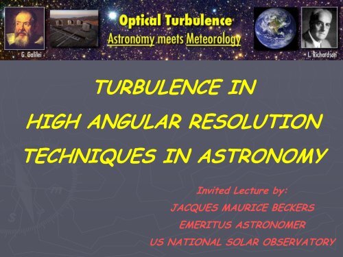
TURBULENCE IN<br />
HIGH ANGULAR RESOLUTION<br />
TECHNIQUES IN ASTRONOMY<br />
Invited Lecture by:<br />
JACQUES MAURICE BECKERS<br />
EMERITUS ASTRONOMER<br />
US NATIONAL SOLAR OBSERVATORY
WHY DO I LIKE THIS CONFERENCE<br />
The study of temperature fluctuations on a small scale<br />
(~ 5 cm) in the Earth’ atmosphere is of great importance<br />
for astronomical observations. More interest by<br />
Meteorologists for such research would be most welcome.
DETRIMENTAL EFFECTS BY THE ATMOSPHERE<br />
ON ASTRONOMICAL OBSERVATIONS<br />
(1) ABSORPTION & SCATTERING<br />
⇒ (a) most of the electro-magnetic<br />
spectrum can only be observed from space<br />
(b) at optical wavelengths extinction limits photometry<br />
(c) scattering limits solar corona observations<br />
(2) REFRACTION<br />
⇒ (a) atmospheric dispersion/refraction<br />
(b) atmospheric turbulence “seeing” limits resolution<br />
(c) atmospheric turbulence “scintillation/twinkling”<br />
limits photometry<br />
ESO<br />
(3) POLLUTION<br />
⇒ (a) contrails limit photometry<br />
(b) mirror coating deterioration<br />
(c) thermal emissivity by dust etc.
DETRIMENTAL EFFECTS BY THE ATMOSPHERE<br />
ON ASTRONOMICAL OBSERVATIONS<br />
“SPECKLE IMAGE” OF STAR<br />
NOTICE: (i) speckle size = size of Airy disk of telescope<br />
(ii) speckles colored (diffraction phenomena)<br />
(iii) number of Speckles N sp<br />
≈ (D/r o<br />
) 2 . D = Telescope Diameter<br />
r 0<br />
= “Fried Parameter” = 10 cm for 1” seeing @ 500nm<br />
D = 10m N sp<br />
≈ 10000<br />
(iv) speckle image changes rapidly (≥ 10 Hz)<br />
(v) for D ≤ r 0<br />
Airy disk N = 1<br />
(one speckle) which “dances”<br />
(2) REFRACTION<br />
(a) atmospheric dispersion/refraction<br />
(b) atmospheric turbulence “seeing” limits resolution<br />
(c) atmospheric turbulence “scintillation/twinkling”<br />
limits photometry<br />
ESO/Paranal<br />
MOON<br />
NOTICE: (i) image motions<br />
(ii) “Iso-Kinetic Patch”<br />
[(iii) “Iso-Planatic Patch”]
SO: WHY BOTHER WITH GROUND-BASED TELESCOPES<br />
SPACE OBSERVATORIES HAVE:<br />
‣ NO ATMOSPHERIC ABSORPTION : RESULTS IN FULL WAVELENGTH ACCESS<br />
⇒ BROAD COVERAGE OF PHYSICAL PROCESSES (many space observatories)<br />
‣ NO ATMOSPHERIC SEEING : RESULTS IN HIGH RESOLUTION IMAGING<br />
⇒ RESOLVE STARS, GALAXIES PLANETS, EXOPLANETARY SYSTEMS etc. (HST)<br />
‣ NO SCINTILLATION : RESULTS IN PRECISION PHOTOMETRY<br />
⇒ EXOPLANET TRANSITS; ASTROSEISMOLOGY (COROT)<br />
‣ LOW THERMAL BACKGROUND : VASTLY IMPROVES INFRARED OBSERVATIONS<br />
⇒ COLD MATTER, STAR FORMATION, etc. (JWST)<br />
‣ LOW ATMOSPHERIC SCATTERED LIGHT : HELPS CORONAGRAPHY (SOHO-LASCO)<br />
⇒ EXOPLANET IMAGING; OTHER HIGH CONTRAST OBJECTS<br />
BUT:<br />
SPACE-BASED FACILITIES ARE MANY ORDERS-OF-MAGNITUDE (100x to<br />
1000x; more) MORE COSTLY THAN GROUND-BASED FACILITIES<br />
⇒ COST IS THE MAIN DRIVER FOR PURSUING HIGH-RESOLUTION<br />
TECHNIQUES FOR GROUND-BASED TELESCOPES AND INTERFEROMETERS
WAVEFRONT DISTURBANCE BY REFRACTIVE INDEX (n) CHANGES<br />
∆y<br />
d<br />
n 2<br />
n 1<br />
Sea Level<br />
RH = 1<br />
∆x = (n 2 -n 1 )*d<br />
∆φ = ∆x/λ<br />
∆x<br />
NOTE: ∆x , dx/dy (tilt) and<br />
d 2 x/dy 2 (curvature)<br />
are achromatic if<br />
n is λ-independent<br />
CIRCLES: RH = 1 AIR<br />
Cerro Paranal<br />
RH = 0<br />
RADIO<br />
WAVES<br />
R.J. Mather, 2004<br />
ANOMALOUS DISPERSION EFFECTS<br />
J H K L M<br />
NOTE:<br />
(i) in general refractive index is function of<br />
temperature & water vapor (RH)<br />
(ii) in optical/IR water vapor has little effect;<br />
T (⇒ P & density) variations dominate seeing.<br />
(iii) in radio & far-IR astronomy water vapor<br />
variations dominate “seeing”<br />
(iv) anomalous dispersion effects occur mostly<br />
outside atmospheric transmission windows;<br />
they have minor effects on n variations<br />
(and do not “compensate seeing” as I had hoped many years ago)
HEIGHT VARIATION OF REFRACTIVE INDEX FLUCTUATIONS<br />
Structure Function: D n (ρ) ≡ r ≡ C n2 |ρ| 2/3 for Kolmogorov turbulence<br />
Height Variation of C n2 (h) according to “Hufnagel-Valley model”:<br />
Roddier (1981)<br />
day<br />
night<br />
Beckers (1993)<br />
boundary layer in daytime<br />
free<br />
atmosphere<br />
‣ Boundary layer control is a major issue in site selection & development<br />
‣ Actual C n2 (h) changes with location, time & wind profile<br />
‣ In daytime lake locations and Antarctic Dome C have very low boundary layer<br />
‣ Balloon observations show major small scale height structure in C n2 (h)
SEEING CONDITIONS AT DOME C<br />
Annual Variation at Different Heights<br />
2835 m<br />
FRENCH-ITALIAN<br />
CONCORDIA STATION AT DOME C<br />
3810 m<br />
4100 m<br />
3250 m<br />
WINTER<br />
SUMMER<br />
Summer/Daytime Seeing at 8.5m Height<br />
1.3<br />
Winter Seeing at 8.5<br />
m<br />
Winter Seeing at 30 m<br />
AGABI et al. 2006 ARNAUD et al. 2007
Height (meters)<br />
WINTER<br />
SUMMER<br />
SEEING ABOVE INDICATED HEIGHT<br />
CALCULATED FROM BALLOON C n2 (h)<br />
OBSERVATIONS<br />
BEST SUMMER/DAYTIME SEEING AT<br />
8.5 m HEIGHT (0.3”) IS CLOSE TO<br />
FREE ATMOSPHERE SEEING (0.25”)<br />
AVERAGE MID-SUMMER/DAYTIME<br />
SEEING (0.7”) IS ABOUT 50% OF<br />
WINTER SEEING AT 8.5 m HEIGHT<br />
ROUGH SURFACE ENERGY BALANCE:<br />
ASSUME STEADY STATE & LOCAL<br />
CONDITIONS EXTEND EVERYWHERE<br />
IN WINTER SURFACE COLDER THAN<br />
THE AIR<br />
IN SUMMER SOLAR RADIATION EQUALIZES<br />
SURFACE AND AIR TEMPERATURES<br />
REAL SITUATION IS NON-STEADY & NON-LOCAL
SPATIAL POWER SPECTRUM OF WAVEFRONT DISTURBANCES<br />
L 0<br />
l 0<br />
Κ (m -1 )<br />
NOTE: A LOW OUTER SCALE<br />
COMBINED WITH VERY<br />
GOOD SEEING IS A GOOD<br />
THING ESPECIALLY FOR<br />
INTERFEROMETRY<br />
‣ inner scale of turbulence (l 0 ≈ 1 cm)<br />
is of little interest for astronomy<br />
(in contrast to laser propagation)<br />
‣ outer scale of turbulence (L 0 ) is of<br />
major interest for astronomy since:<br />
(i) it has dimensions comparable to<br />
the diameters of Large Telescopes<br />
(D ≈ 8 m for VLTs to 42 m for ELTs)<br />
(ii) it is small compared to the baselines<br />
of <strong>Optical</strong> Interferometers<br />
(e.g. VLTI 200 m ; CHARA 330 m )<br />
‣ L 0 depends on number of factors (like<br />
dome size, landscape, vegetation,<br />
height, telescope structure, radiation<br />
cooling, height)<br />
‣ measured L 0 : La Palma/Hershell 2 m<br />
Sydney/SUSI 5 m<br />
Palomar/PTI 16 m<br />
Paranal 22 m<br />
Mauna Kea 27 - 50 m<br />
OHP/France 14 m<br />
‣ it is quite possible for a site to have<br />
multiple outer scales !!!
“Fried Parameter” r 0 definition:<br />
For Telescope Diameter D and r 0 = D the<br />
RMS Wavefront Distortion Equals 1/6 Wave<br />
<br />
Diffraction limited Image<br />
For Larger D/r o RMS Wavefront Disturbances<br />
Increase as (D/r 0 ) 5/6 Imaging Deteriorates
A FEW MORE EXPRESSIONS (for Zenith Angle = 0)<br />
Fried Parameter r 0 (:) λ 6/5 (∫C n2 dh) -3/5<br />
Image Size (FWHM) = λ/r 0 (radians) (:) λ -1/5 (∫C n2 dh) 3/5<br />
RMS Image Motion (:) D -1/3 ∫C n2 dh<br />
Scintillation Index Stars= (∆I RMS /I) 2 (:) λ -7/6 ∫h 5/6 *C n2 dh<br />
Scintillation Index Sun/Moon= (∆I RMS /I) 2 (:) ∫h -1/3 *C n2 dh<br />
Time Constant τ ≈ r 0 / Cn2 (uses Taylor approximation)<br />
Radius of “Isoplanatic Patch” φ 0 ≈ 0.3 r 0 / Cn2<br />
Number of Speckles ≈ (D/r o ) 2<br />
Speckle Size = λ/D (radians)<br />
For more detail see:<br />
F. Roddier, “The Effects of Atmospheric <strong>Turbulence</strong> in <strong>Optical</strong> Astronomy”<br />
in Progress in Optics 19, 281, 1981.
REMOVING SEEING EFFECTS IN TELESCOPE IMAGING<br />
THROUGH ADAPTIVE OPTICS (“AO”): CONCEPT<br />
‣ Originally proposed by H. Babcock (1953)<br />
‣ Is complex servo system involving 3 parts:<br />
(1) measurement of Atmospheric Wavefront<br />
distortion on “Reference Star or Beacon”<br />
(2) uses a “Deformable Mirror” to flatten the<br />
wavefront<br />
(3) uses a Processor to couple the wavefront<br />
sensor and the deformable mirror<br />
for 0.75 arcsec seeing & 10m/s wind:<br />
λ<br />
(μm)<br />
r 0<br />
(cm)<br />
τ 0<br />
(sec)<br />
φ 0<br />
( “ )<br />
Sky<br />
Coverage<br />
0.55 15 .015 1.9 .0003%<br />
1.25 40 .040 5.1 .05%<br />
2.2 80 .079 10.1 1.3%<br />
‣ Servo loop has to correct the wavefront<br />
with spatial resolution of ≤ r 0 and temporal<br />
resolution ≤ τ 0 (see table on the left)<br />
‣ Reference object has to be within Isoplanatic<br />
Patch φ 0 and could be object/star itself<br />
‣ Since r 0 , τ and φ 0 increase with wavelength<br />
AO is being implemented first in the IR<br />
‣ All major Solar Telescopes now have adaptive<br />
optics. Some Nighttime Telescopes have<br />
‣ To provide all sky coverage at night many<br />
efforts are focused on artificial stars<br />
(Laser Beacons or Laser Guide Stars=LGSs)
OF SPECIAL INTEREST FOR THE TOPIC OF THIS CONFERENCE:<br />
WAVEFRONT SENSING = ATMOSPHERIC TURBULENCE SENSING!<br />
Three methods are used to sense the wavefront:<br />
(A) Wavefront Tilt sensing using Shack-Hartman Sensor<br />
image of telescope pupil<br />
• For longer wavelengths (> 500 nm) wavefront tilts<br />
are close to achromatic<br />
• So wavefront sensing at visible wavelengths using<br />
CCD arrays can be used for IR astronomy<br />
• Number of lenslets = (D/r 0 ) 2 ≈ 5000 for D = 10 m<br />
BMC<br />
• Algorithm needed for wavefront reconstruction<br />
from wavefront tilts (e.g. Zernike expansion)<br />
(B) Wavefront Curvature Sensing using Roddier-Beckers Sensor<br />
• Out-of-Focus images of original MMT mirrors<br />
showed ring- and other structure.<br />
• Interpreted by JMB to correspond to wavefront<br />
curvature.<br />
• F. Roddier then incorporated Out-of-Focus images<br />
as the sensor for his “Curvature Adaptive Optics”<br />
(C) Faucoult Knife Edge Test ⇔ Ragazzoni Pyramid Wavefront Sensor
SOME EXAMPLES OF IMAGES RESTORED BY ADAPTIVE OPTICS<br />
STAR IMAGE<br />
NGC 1097 (ESO-VLT)<br />
no AO<br />
with AO<br />
no AO<br />
NEPTUNE (KECK TELESCOPE)<br />
SUNSPOT (NSO DUNN TELESCOPE)<br />
with AO<br />
with AO<br />
HUMAN RETINA (A. ROORDA)<br />
with AO<br />
no AO<br />
no AO<br />
with AO
SODIUM (& RAYLEIGH) “LASER GUIDE STARS” (or “Laser Beacons”)<br />
Keck Observatory<br />
Uses Na-lasers at 589 nm wavelength<br />
Scattered radiation on 95 km high atomic Sodium<br />
layer creates artificial star of about 1 arcsec size<br />
This “Laser Guide Star”, or LGS, is not at infinity.<br />
Therefore (i) its focus is behind the nominal focus<br />
of the telescope and (ii) the light received is a<br />
cone rather than as cylinder (“Cone Effect”)<br />
The Cone Effect requires multiple LGSs to infer<br />
the wavefront coming from the actual star<br />
Laser power limits (~ 10W) the LGS brightness to<br />
V ~ 9 (depends strongly on laser properties and<br />
on Mesospheric Na density)<br />
Laser is best transmitted from<br />
the telescope center to minimize<br />
the elongation of the LGS due<br />
to the 10 km Na-layer thickness<br />
Rayleigh Scattering<br />
laser location<br />
LGS perspective elongation<br />
Keck
INCREASING THE CORRECTED AREA ON THE SKY<br />
BY MULTI-CONJUGATE ADAPTIVE OPTICS<br />
CONCEPT:<br />
Place N Deformable Mirrors (DM)<br />
at N Images of Conjugated<br />
Layers of the Atmosphere<br />
Example: Ground Layer and<br />
Tropopause (here: N = 2)<br />
Deform each Mirror to Correct<br />
Wavefront at that Layer<br />
Measure Wavefront of M (≥ N)<br />
Stars with M Wavefront<br />
Sensors (here: M = 2)<br />
Using Tomography Techniques<br />
Estimate the Wavefront<br />
Distortion at Different Layers.<br />
Technique is referred to as<br />
“Atmospheric Tomography” or AT<br />
=TOMOGRAPH (“CAT”)
“TRADITIONAL TOMOGRAPHY” IN MEDICINE<br />
MOVING X-RAY SOURCE<br />
STATIONARY OBJECT/SUBJECT (HUMAN BODY)<br />
IMAGE PLANE<br />
MOVING PHOTOGRAPHIC FILM<br />
“DEFOCUSSED” BODY CAUSES “BACKGROUND”<br />
“TOMOGRAPHIC ANGLE” IS LARGE<br />
ASTRONOMY VERSION OF TRADITIONAL TOMOGRAPHY<br />
Using Natural Guide Stars. Problem:<br />
Only works in clusters of stars<br />
Using Laser Guide Stars. Problem:<br />
Need to also correct Cone Effect<br />
For N = 4 Patch<br />
Diameter increases<br />
by 2N x or 8 x<br />
SCAO<br />
MCAO
SOLAR S-H<br />
WAVEFRONT<br />
SENSOR FOR<br />
ATMOSPHERIC<br />
TOMOGRAPHY<br />
127”<br />
725 mm<br />
73 mm<br />
Configuration:<br />
NSO Dunn Solar<br />
Telescope<br />
D = 76.2 cm<br />
Wavelength = 411 nm<br />
Bandwidth = 2.5 nm<br />
CCD: 2078 x 2108<br />
pixel size 13.8 μm<br />
= 0.623 arcsec<br />
FOV=127” x 127”<br />
Exp. Time = 10 ms
COMPUTER AIDED TOMOGRAPHY<br />
(“CAT”) IN MEDICINE USES<br />
LINEAR X-RAY SOURCE/DETECTOR<br />
ARRAYS & COMPUTER 2D IMAGE<br />
RECONSTRUCTION.<br />
ADD 1D SCANNING ⇒ 3D IMAGES.<br />
NOTE: LARGE TOMOGRAPHIC ANGLE<br />
IN ATMOSPHERIC TOMOGRAPHY ASTRONOMERS USE:<br />
2D NATURAL OR LASER GUIDE STAR ARRAYS<br />
2D DETECTOR ARRAYS, ONE FOR EACH GUIDE STAR<br />
VERY SMALL TOMOGRAPHIC ANGLES (~ 1 arcmin)<br />
COMPUTER AIDED RECONSTRUCTION<br />
‣ BALLOON, SCIDAR AND OTHER C n2 (h) PROFILING<br />
TOOLS GENERALLY SHOWS A NUMBER OF<br />
DOMINANT THIN OPTICAL TURBULENT LAYERS<br />
‣ EVENTUALLY (I SUSPECT) AT & MCAO WILL<br />
INCLUDE REAL-TIME C n2 (h) KNOWLEDGE TO<br />
OPTIMIZE THE 3D TOMOGRAPHY AND THE<br />
CHOICE OF THE DM CONJUGATE HEIGHTS.<br />
10% best seeing<br />
median seeing<br />
Mauna Kea<br />
SCIDAR
NAME<br />
Balloons<br />
SCIDAR<br />
G-SCIDAR<br />
S-S S SCIDAR<br />
LOLAS<br />
DASS<br />
PlaSci<br />
MOSP<br />
SODAR<br />
SNODAR<br />
A LARGE NUMBER OF C n2 (h) RANGE PROFILING TOOLS EXIST<br />
h-RANGE<br />
∆h FULL NAME & COMMENTS<br />
All h<br />
greater h<br />
all h<br />
greater h<br />
low h<br />
HVR-GS<br />
all h<br />
all h<br />
low h<br />
low h<br />
~ 1 m Direct C 2 T (h) C 2 n (h); ; only occasionally available<br />
~ 200 m SCIntillation<br />
Detection<br />
And<br />
Ranging<br />
requires ~ 1 to 3 m telescope & binary star<br />
~ 200 m Generalized<br />
SCIDAR<br />
requires ~ 1 to 3 m telescope & binary star<br />
modest<br />
Single<br />
Star<br />
SCIDAR<br />
LOw LAyer<br />
Scidar<br />
needs small telescope and wide binary angle<br />
~ 25 m High<br />
Velocity<br />
Resolution<br />
G Scidar<br />
needs small scale velocity structure with height<br />
Double-Aperture<br />
Scintillation<br />
Sensor<br />
MASS greater h ~ 400 m Multi-Aperture<br />
Scintillation<br />
Sensor<br />
SHABAR<br />
low h<br />
SHABAR-P all h<br />
LuSci<br />
SLODAR<br />
low h<br />
~ 400 m SHAdow<br />
BAnd<br />
Ranger<br />
uses scintillometer array on Sun or Moon<br />
~ 400 m SHABAR Planet version<br />
Planetary<br />
Scintillometer (Planet version of SHABAR)<br />
~ 400 m Lunar<br />
Scintillometer (Lunar version of SHABAR)<br />
Monitor of Wavefront Outer<br />
Scale<br />
Profiles<br />
SLOpe<br />
Detection<br />
And<br />
Ranging<br />
similar to SCIDAR but uses WFS iso scintillation<br />
SOnic<br />
Detection<br />
And<br />
Ranging<br />
uses scattering by sound waves on turbulence<br />
1 m Surface layer NOn-Doppler<br />
Acoustic<br />
Radar
STATUS OF MCAO DEVELOPMENTS<br />
N=2 only (“Dual Conjugate Adaptive Optics”)<br />
Solar Observatories (KIS; NSO) using “Guide-<br />
Fields” and visible wavelengths (0.5 μm).<br />
Nighttime Observatories in NIR (2.2 μm)<br />
using either:<br />
(i) Natural Guide Stars (ESO-MAD/VLT) or<br />
(ii) Laser Guide Stars (GEMINI-S; being<br />
commissioned)<br />
Laboratory trials ( CfAO/Santa Cruz; Lund<br />
(Observatory)<br />
NSO-DST<br />
(0.8 m ;0.5 μm)<br />
ESO-MAD/VLT (8 m ;2.2 μm)<br />
no AO<br />
MCAO<br />
20”<br />
Guide Fields<br />
44”
THE MANY FLAVORS OF ADAPTIVE OPTICS<br />
AT only<br />
MOAO<br />
Multi-<br />
Object<br />
LTAO<br />
Laser<br />
Tomography<br />
SCAO<br />
Single<br />
Conjugate<br />
MCAO<br />
&<br />
AT<br />
GLAO<br />
Ground<br />
Layer<br />
DCAO<br />
Dual<br />
Conjugate<br />
LOAO a<br />
Layer<br />
Oriented<br />
“Full”<br />
MCAO<br />
LOAO b<br />
Low<br />
Order<br />
ExAO<br />
Extreme<br />
PSAO<br />
Pupil<br />
Slicing<br />
MCAO & AT
THE MANY FORMS OF ASTRONOMICAL ADAPTIVE OPTICS<br />
AO<br />
MCAO<br />
AT<br />
SCAO<br />
DCAO<br />
GLAO<br />
Adaptive Optics Original concept proposed by Babcock (’1959)<br />
Multi-Conjugate AO<br />
Atmospheric Tomography<br />
Single Conjugate AO<br />
Uses multiple DMs conjugated at different heights to<br />
increase FOV (Beckers, 1988)<br />
Gives 3D refractive structure of atmosphere by<br />
tomography using many guide stars (J. Beckers, 1988).<br />
Removes also the cone effect for LGS.<br />
MCAO conjugated to only one height.<br />
Dual Conjugate AO MCAO conjugated to two heights (eg(<br />
ground and<br />
tropopause).<br />
Ground-Layer AO MCAO conjugated to the ground layer (Rigaut(<br />
Rigaut, , 2001)<br />
LOAO a<br />
LOAO b<br />
MOAO<br />
LTAO<br />
ExAO<br />
PSAO<br />
Layer Oriented AO<br />
Low Order AO<br />
Multi-Object AO<br />
Laser Tomography AO<br />
Extreme AO<br />
Pupil Slicing AO<br />
MCAO using optical means on stars (instead of AT) to<br />
sense wavefronts at MCAO conjugates (Ragazzoni(<br />
Ragazzoni, , 2001)<br />
Corrects only large scale wavefront Distortions<br />
Uses separate SCAO for each of a number of objects<br />
(Hubin).<br />
Same as SCAO/AT combination to remove cone effect<br />
for Laser Guide Stars (UofA, 2005).<br />
AO designed to have minimal light in the wings of the<br />
Point-Spread<br />
Spread-Function for High Contrast Imaging.<br />
Uses a number of DMs in segmented/sliced pupil (Beckers<br />
et al. 2006).
MANAGING SEEING EFFECTS IN INTERFEROMETRY<br />
There are two types of Astronomical Imaging Interferometers:<br />
(i) “Monolithic” Interferometers (e.g. Fizeau Experiment; MMT; LBT)<br />
‣ <strong>Optical</strong> Path Differences (OPD) are small and<br />
constant<br />
‣ Pupil-in = Pupil-out leads to large Field-of View<br />
(FOV) also called “Homothetic Imaging”<br />
‣ Without AO ⇒<br />
“Fringed Speckles”<br />
‣ AO badly needed!<br />
(ii) “Non-Monolithic Interferometers (e.g. VLTI; CHARA; COAST; KECK-I ++)<br />
‣ OPDs are very large (up to few hundred meters), vary rapidly with time and are chromatic<br />
‣ OPD correction needs fast variable Delay Lines (DLs) with Chromatic Correction<br />
‣ Homothetic imaging can be done but has not been implemented (yet) ⇒ currently very small FOV<br />
‣ Dual field interferometry using unresolved object in one field allows Co-Phasing (needs 2 DLs)
CO-PHASED AND COHERENT INTERFEROMETERS<br />
Fringe spacing varies with<br />
Wavelength ⇒ Colored Fringes<br />
Coherence Length = OPD range<br />
With high fringe contrast<br />
Scan of Delay Line ( = OPD variation) ⇒<br />
Zero <strong>Optical</strong> Path Difference ⇒ “White Light Fringe” (WLF)<br />
In the “CO-PHASED MODE” the OPDs in the interferometer arms have to be very<br />
close to zero (within fraction of a wavelength)<br />
This requires using the WLF on an unresolved star within the Field-Of-View of the<br />
interferometer for homothetic interferometers or a differential Delay Line on a<br />
nearby star (at VLTI this is done with PRIMA). Fringes are tracked on that star.<br />
Because the WLF is used a broad wavelength range can be used (wide color bands)<br />
In the “COHERENT MODE” the OPDs in the interferometer have to be within the<br />
coherence length (CL). CL = λ * (λ/∆λ) = λ 2 /∆λ. This requires narrow color bands.<br />
Fringes have good contrast but cannot be tracked. They may be hidden in photon noise.<br />
If at least 3 interferometer arms are used one can use the “Triple Correlation<br />
Technique” for the combined image analysis.<br />
Average Triple Correlations ⇒“Closure Phases”⇒ Images (as in Radio Interferometers)
TRIPLE CORRELATION/BISPECTRUM ANALYSIS<br />
AND CLOSURE PHASE IMAGING<br />
‣ How to derive phase (and amplitude) information in “Coherent” interferometry<br />
‣ No fringe tracking ⇒ fringe positions change rapidly (< second scale)<br />
because of atmospheric seeing and instrumental effects.<br />
‣ The same problem was encountered in radio astronomy in radio interferometry<br />
many years ago and solved with “CLOSURE PHASE” techniques (R. Jennison, 1958)<br />
‣ It requires the use of at least 3 Interferometer arms ( with 3 telescopes)<br />
• Intensity in Short Exposure Combined Image ≡ I(x,x’) (x values are vectors)<br />
• Triple Correlation TC( x,x’) ≡ ∫ I(x”) I(x”+x) I(x”+x’) dx”<br />
• TC(x,x’) shows 3 correlation peaks at 3 spatial frequencies with observed phases<br />
φ, φ’ and φ” each one consisting of the true phase Φ and an atmospheric error ε<br />
• So: φ = Φ+ε ; φ’ = Φ+ε’ and φ” = Φ”+ε” where ε” = ε+ε’<br />
• ⇒ Φ + Φ’ -Φ” = φ + φ’ -φ”<br />
• Two of the phases e.g. Φ and Φ’ are related to the position of the object. They<br />
can be taken as a given like (0,0) ⇒ Φ” (“closure phase”) over distance x” .<br />
• There have to be enough photons to allow the determination of φ, φ’ and φ” in<br />
the amount of time during which the ε values change by a fraction of 2π .<br />
NOTE: COHERENT IMAGING USING CLOSURE PHASES HAS YET NOT BEEN USED
CONCLUDING REMARKS<br />
1. IMAGE RECOVERY FROM THE COMPLEX ATMOSPHERIC OPTICAL TURBULENCE<br />
DISTORTIONS IS POSSIBLE .<br />
2. HOWEVER DOING SO IS TECHNICALLY VERY TIME CONSUMING AND EXPENSIVE<br />
3. FOR EXAMPLE: (i) “CLASSICAL AO” (or SCAO) PROPOSED BY BABCOCK IN 1953.<br />
FIRST ASTRONOMICAL OPERATING SYSTEM IN 1988 (AT ESO)<br />
4. MAJOR NEEDS NOW ARE:<br />
(ii) “MULTICONJUGATE ADAPTIVE OPTICS (MCAO) WAS<br />
PROPOSED IN 1988. IN ITS SIMPLEST FORM (DCAO) IT WAS<br />
FIRST OPERATIVE IN 2004 (at NSO, Sun) & 2008 (ESO, stars).<br />
(a) Extension of AO to shorter wavelengths<br />
(b) Production of numerous ( ≥10 4 ) actuator, large stroke DMs as<br />
needed for ELTs and ExAO<br />
(c) Production of Adaptive Secondary Mirrors<br />
(d) Development of optimum Atmospheric Tomography algorithms<br />
(e) Construction of more powerful pulsed Sodium Lasers<br />
(f) Removal of Perspective Elongation of Laser Guide Stars<br />
(g) Moving from DCAO to full MCAO<br />
(h) In Interferometric Imaging: Development of Imaging Algorithms<br />
probably building on Radio Interferometry expertise.
THANK YOU!


