
Create successful ePaper yourself
Turn your PDF publications into a flip-book with our unique Google optimized e-Paper software.
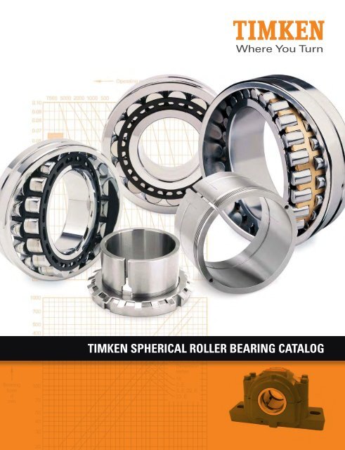
TIMKEN SPHERICAL ROLLER BEARING CATALOG
SPHERICAL ROLLER BEARING METRIC ACCESSORIES<br />
NOTES<br />
184 TIMKEN SPHERICAL ROLLER BEARING CATALOG
TIMKEN<br />
OVERVIEW<br />
SPHERICAL ROLLER BEARING<br />
CATALOG INDEX<br />
TIMKEN OVERVIEW. . . . . . . . . . . . . . . . . . . . . . . . . . . . . . . . . . . . . . . . . 2<br />
SHELF LIFE POLICY . . . . . . . . . . . . . . . . . . . . . . . . . . . . . . . . . . . . . . . . . 6<br />
INTRODUCTION . . . . . . . . . . . . . . . . . . . . . . . . . . . . . . . . . . . . . . . . . . . . 8<br />
ENGINEERING<br />
<strong>Bearing</strong> Types and Cages . . . . . . . . . . . . . . . . . . . . . . . . . . . . . . . . . . . 12<br />
Metric System Tolerances . . . . . . . . . . . . . . . . . . . . . . . . . . . . . . . . . . 14<br />
Mounting, Fitting, Setting and Installation Practices . . . . . . . . . . . 17<br />
Shaft and Housing Fits . . . . . . . . . . . . . . . . . . . . . . . . . . . . . . . . . . . . . 25<br />
Operating Temperatures . . . . . . . . . . . . . . . . . . . . . . . . . . . . . . . . . . . . 42<br />
Heat Generation and Dissipation . . . . . . . . . . . . . . . . . . . . . . . . . . 45<br />
Torque . . . . . . . . . . . . . . . . . . . . . . . . . . . . . . . . . . . . . . . . . . . . . . . . . . . 46<br />
Lubrication . . . . . . . . . . . . . . . . . . . . . . . . . . . . . . . . . . . . . . . . . . . . . . . 47<br />
SPHERICAL ROLLER BEARINGS<br />
<strong>Spherical</strong> <strong>Roller</strong> <strong>Bearing</strong>s. . . . . . . . . . . . . . . . . . . . . . . . . . . . . . . . . . . 59<br />
<strong>Spherical</strong> <strong>Roller</strong> <strong>Bearing</strong> Pillow Blocks . . . . . . . . . . . . . . . . . . . . . . . 89<br />
<strong>Spherical</strong> <strong>Roller</strong> <strong>Bearing</strong> Inch and Metric Accessories . . . . . . . . 127<br />
TIMKEN SPHERICAL ROLLER BEARING CATALOG 1
TIMKEN<br />
OVERVIEW<br />
TIMKEN. WHERE YOU TURN.<br />
Turn to <strong>Timken</strong> to move ahead of the competition and stand out<br />
as a leader in your industry.<br />
When you turn to us, you receive more than high-quality<br />
products and services; you acquire a worldwide team of highly<br />
trained and experienced associates, eager to help you keep<br />
production rates high and downtime low.<br />
Whether it is a wheel assembly for a family vehicle, bearings<br />
outfitted for a deep-sea oil drilling rig, repair services for rail<br />
bearings or steel for an aircraft engine shaft, we supply the<br />
products and services you need that help keep the world<br />
turning.<br />
FRICTION MANAGEMENT<br />
SOLUTIONS – A TOTAL SYSTEMS<br />
APPROACH<br />
Your industry is ever-changing, from the evolution of advanced<br />
motion-control systems to the demands from your customers.<br />
Turn to us to stay ahead of the curve.<br />
We use our friction-management know-how to offer solutions<br />
that maximize performance, fuel-efficiency and equipment<br />
life. We also offer integrated services that extend well<br />
beyond bearings, including condition monitoring systems and<br />
services, encoders and sensors, seals, premium lubricants and<br />
lubricators.<br />
<strong>Timken</strong>’s wide range of friction management solutions can<br />
include evaluations of your entire system – not just individual<br />
components. This provides cost-effective solutions to help you<br />
reach specific application goals. Working together, we help<br />
you meet these demands and ensure all your systems<br />
run smoothly.<br />
2 TIMKEN SPHERICAL ROLLER BEARING CATALOG
TIMKEN<br />
OVERVIEW<br />
TECHNOLOGY THAT MOVES YOU<br />
Innovation is one of our core values, and we’re known for our<br />
ability to solve engineering challenges.<br />
We focus on improving performance in the most difficult<br />
applications, and we’re passionate about creating technical<br />
solutions and services that help your equipment perform faster,<br />
harder, smoother and more efficiently.<br />
To do this, we invest in:<br />
• People, attracting and hiring scholars, engineers and<br />
specialists from across the globe who are experts in<br />
mechanical power transmission, antifriction bearing<br />
design, tribology, metallurgy, clean steel production,<br />
precision manufacturing, metrology and engineered<br />
surfaces and coatings.<br />
• Tools, including state-of-the-art laboratories, computers<br />
and manufacturing equipment.<br />
• The Future, identifying new concepts that make you a<br />
standout in your industry for years to come. Our ongoing<br />
investment in research and development activities allows<br />
us to grow our capabilities, expand our product and<br />
service portfolio and deliver value over the<br />
long term.<br />
We’re committed to finding new avenues for<br />
system sustainability. In the area of power<br />
density, we’re creating systems where<br />
we replace larger, more cumbersome<br />
components with smaller, more efficient<br />
bearings to help improve systems’<br />
performance.<br />
We carry on this sustainable difference<br />
across the globe. Wherever you’re<br />
located, you can count on us at technology<br />
centers in North America, Europe and Asia –<br />
as well as in our manufacturing facilities and<br />
field offices on six continents – to develop ideas<br />
and resources to transform your concepts into reality.<br />
TIMKEN SPHERICAL ROLLER BEARING CATALOG 3
TIMKEN<br />
OVERVIEW<br />
A BRAND YOU CAN TRUST<br />
The <strong>Timken</strong> brand stands for quality, innovation<br />
and dependability.<br />
We take pride in the quality of our work, and you<br />
gain the peace-of-mind of knowing that each<br />
box contains an industry-trusted product. As our<br />
founder Henry <strong>Timken</strong> said, “Don’t set your name to<br />
anything you will ever have cause to be ashamed of.”<br />
We<br />
continue this mindset through the <strong>Timken</strong> Quality<br />
Management System (TQMS). With TQMS, we promote<br />
continuous quality improvements in our products and<br />
services to our global operations and supply chain networks.<br />
It helps us ensure that we’re consistently applying quality<br />
management practices throughout the company. We also<br />
register each of our production facilities and distribution<br />
centers to the appropriate quality system standards for the<br />
industries they serve.<br />
ABOUT THE TIMKEN COMPANY<br />
The <strong>Timken</strong> Company keeps the world turning with innovative<br />
friction management and power transmission products and<br />
services that are critical to help hard-working machinery to<br />
perform efficiently and reliably. With sales of $4.1 billion in<br />
2010, and operations in 30 countries with approximately 20,000<br />
people, <strong>Timken</strong> is Where You Turn ® for better performance.<br />
4 TIMKEN SPHERICAL ROLLER BEARING CATALOG
TIMKEN<br />
OVERVIEW<br />
ABOUT THIS MANUAL<br />
<strong>Timken</strong> offers an extensive range of bearings and accessories<br />
in both imperial and metric sizes. For your convenience, size<br />
ranges are indicated in millimeters and inches. Contact your<br />
<strong>Timken</strong> engineer to learn more about our complete line for the<br />
special needs of your application.<br />
USING THIS MANUAL<br />
We are committed to providing our customers with maximum<br />
service and quality. This publication contains dimensions,<br />
tolerances and load ratings as well as an engineering section<br />
describing fitting practices for shafts and housings, internal<br />
clearances, materials and other bearing features. It can<br />
provide valuable assistance in the initial consideration of the<br />
type and characteristics of the bearing that may best suit your<br />
particular needs.<br />
Every reasonable effort has been made to ensure the accuracy<br />
of the information contained in this writing, but no liability is<br />
accepted for errors, omissions or for any other reason.<br />
<strong>Timken</strong> products are sold subject to <strong>Timken</strong>’s terms and<br />
conditions of sale, including its limited warranty and remedy.<br />
Please contact your <strong>Timken</strong> engineer with questions.<br />
MANUAL FEATURES<br />
ISO and ANSI/ABMA, as used in this publication, refer to<br />
the International Organization for Standardization and the<br />
American National Standards Institute/American <strong>Bearing</strong><br />
Manufacturers Association.<br />
NOTE<br />
Product performance is affected by many factors beyond the<br />
control of <strong>Timken</strong>. Therefore, the suitability and feasibility of all<br />
designs and product selection should be validated by you. This<br />
catalog is provided solely to give you, a customer of <strong>Timken</strong><br />
or its parent or affiliates, analysis tools and data to assist you<br />
in your design. No warranty, expressed or implied, including<br />
any warranty of fitness for a particular purpose, is made by<br />
<strong>Timken</strong>. <strong>Timken</strong> products and services are sold subject to a<br />
Limited Warranty.<br />
You can see your <strong>Timken</strong> engineer for more information.<br />
TIMKEN SPHERICAL ROLLER BEARING CATALOG 5
TIMKEN<br />
OVERVIEW<br />
SHELF LIFE AND STORAGE OF<br />
GREASE-LUBRICATED BEARINGS AND COMPONENTS<br />
<strong>Timken</strong> guidelines for the shelf life of grease-lubricated rolling<br />
bearings, components and assemblies are set forth below.<br />
Shelf life information is based on test data and experience.<br />
Shelf life should be distinguished from lubricated bearing/<br />
component design life as follows:<br />
SHELF LIFE POLICY<br />
Shelf life of the grease-lubricated bearing/component<br />
represents the period of time prior to use or installation. The<br />
shelf life is a portion of the anticipated aggregate design life. It<br />
is impossible to accurately predict design life due to variations<br />
in lubricant bleed rates, oil migration, operating conditions,<br />
installation conditions, temperature, humidity and extended<br />
storage.<br />
Shelf life values, available from <strong>Timken</strong>, represent a maximum<br />
limit – and assume adherence to the <strong>Timken</strong> suggested storage<br />
and handling guidelines. Deviations from <strong>Timken</strong>’s storage and<br />
handling guidelines may reduce shelf life. Any specification or<br />
operating practice that defines a shorter shelf life should be<br />
used. <strong>Timken</strong> cannot anticipate the performance of the grease<br />
lubricant after the bearing or component is installed or placed<br />
in service.<br />
TIMKEN IS NOT RESPONSIBLE FOR THE SHELF LIFE<br />
OF ANY BEARING/COMPONENT LUBRICATED BY<br />
ANOTHER PARTY.<br />
STORAGE<br />
<strong>Timken</strong> suggests the following storage guidelines for its<br />
finished products (bearings, components and assemblies,<br />
hereinafter referred to as “Products”):<br />
• Unless directed otherwise by <strong>Timken</strong>, Products should be<br />
kept in their original packaging until they are ready to be<br />
placed into service.<br />
• Do not remove or alter any labels or stencil markings on<br />
the packaging.<br />
• Products should be stored in such a way that the packaging<br />
is not pierced, crushed or otherwise damaged.<br />
• After a Product is removed from its packaging, it should be<br />
placed into service as soon as possible.<br />
• When removing a Product that is not individually<br />
packaged from a bulk pack container, the container should<br />
be resealed immediately after the Product is removed.<br />
• Do not use Product that has exceeded its shelf life as<br />
defined in <strong>Timken</strong>’s shelf life guidelines statement.<br />
• The storage area temperature should be maintained<br />
between 0º C (32º F) and 40º C (104º F); temperature<br />
fluctuations should be minimized.<br />
• The relative humidity should be maintained below 60<br />
percent and the surfaces should be dry.<br />
• The storage area should be kept free from airborne<br />
contaminants such as, but not limited to, dust, dirt,<br />
harmful vapors, etc.<br />
• The storage area should be isolated from undue vibration.<br />
• Extreme conditions of any kind should be avoided.<br />
Inasmuch as <strong>Timken</strong> is not familiar with a customer’s<br />
particular storage conditions, these guidelines are strongly<br />
suggested. However, the customer may very well be required<br />
by circumstance or applicable government requirements to<br />
adhere to stricter storage requirements.<br />
6 TIMKEN SPHERICAL ROLLER BEARING CATALOG
TIMKEN<br />
OVERVIEW<br />
Most bearing<br />
types are typically<br />
shipped protected<br />
with a corrosionpreventive<br />
compound<br />
that is not a lubricant.<br />
Such bearings may be<br />
used in oil-lubricated<br />
applications without removal<br />
of the corrosion-preventive<br />
compound. When using some<br />
specialized grease lubrications, it<br />
is advisable to remove the corrosionpreventive<br />
compound before packing the<br />
bearings with suitable grease.<br />
Some bearing types in this catalog are prepacked with general<br />
purpose grease suitable for their normal application. Frequent<br />
replenishment of the grease may be necessary for optimum<br />
performance. Care must be exercised in lubricant selection,<br />
however, since different lubricants are often incompatible.<br />
When specified by the customer, other bearings may be<br />
ordered pre-lubricated.<br />
Upon receipt of a bearing shipment, ensure that the bearings<br />
are not removed from their packaging until they are ready<br />
for mounting so that they do not become corroded or<br />
contaminated. <strong>Bearing</strong>s should be stored in an appropriate<br />
atmosphere in order that they remain protected for the<br />
intended period.<br />
Any questions concerning shelf life or storage should be<br />
directed to your local sales office.<br />
WARNING<br />
Failure to observe the following warnings could<br />
create a risk of death or serious injury.<br />
Proper maintenance and handling practices are critical.<br />
Always follow installation instructions and<br />
maintain proper lubrication.<br />
Never spin a bearing with compressed air.<br />
The rollers may be forcefully expelled.<br />
TIMKEN SPHERICAL ROLLER BEARING CATALOG 7
SPHERICAL ROLLER BEARING INTRODUCTION<br />
<strong>Timken</strong> high-quality bearings can be put to work in any application where<br />
spherical roller bearings can be specified. Some of these applications are:<br />
8 TIMKEN SPHERICAL ROLLER BEARING CATALOG
SPHERICAL ROLLER BEARING INTRODUCTION<br />
TIMKEN ® SPHERICAL ROLLER BEARINGS – OFFERING SELECTION AND<br />
SUPERIOR PERFORMANCE<br />
Your success depends on the performance of your equipment,<br />
especially when it faces harsh environments and high radial<br />
loads. To help keep uptime high and downtime low, turn to <strong>Timken</strong> ®<br />
spherical roller bearings. These bearings are your best choice<br />
when conditions include heavy loads, when you have difficulties<br />
in establishing or maintaining housing alignment, or when shaft<br />
deflection can be expected.<br />
PRODUCT OFFERING<br />
Our spherical roller bearing product line is one of the broadest<br />
in the industry. <strong>Timken</strong> spherical bearings are available in either<br />
stamped-steel window-type cages or precision-machined-brass<br />
cages with a wide variety of sizes and configurations to meet the<br />
requirements of demanding applications.<br />
You can select product from the complete range of our spherical<br />
roller series as depicted in fig. 1. They are available in 10<br />
dimensional series conforming to ISO and ANSI/ABMA standards.<br />
Our product line includes several designs developed to meet your<br />
applications’ requirements. Sizes range from 25 mm (0.9842 in.)<br />
to 1500 mm bore (59.0551 in.).<br />
<strong>Timken</strong>’s offering includes pillow blocks equipped with spherical<br />
roller bearings. These pillow blocks are made of split construction<br />
for convenient assembly and disassembly.<br />
A wide range of accessories is available to support installation<br />
and removal needs. Use of accessories is the safest and most<br />
effective way to mount and dismount a bearing assembly.<br />
Updates are made periodically to this catalog. Visit<br />
www.timken.com for the most recent version of the <strong>Spherical</strong><br />
<strong>Roller</strong> <strong>Bearing</strong> <strong>Catalog</strong>.<br />
A QUANTUM LEAP<br />
<strong>Timken</strong> has redesigned the spherical roller bearing line, giving<br />
you expanded options for meeting the toughest, most demanding<br />
applications – from heavy-gear and caster applications to the<br />
harshest aggregate and conveyor systems. With higher load and<br />
speed ratings than previous <strong>Timken</strong> spherical roller bearings,<br />
this next generation achieves higher performance levels with<br />
improved surface finishes and innovative features that are<br />
designed to help lower operating temperatures and increase<br />
load-carrying capabilities.<br />
• New cage designs, including a nitrided, stamped steel<br />
slotted cage, help provide better purging of contaminants.<br />
• Optimized internal geometries provide positive axial roller<br />
guidance and improved lubricant distribution.<br />
• Circumferential roller guidance generates positive<br />
hydrodynamic contact, contributing to better roller/cage<br />
interaction.<br />
The result of these innovations is an 18 percent increase in<br />
capacity for a 75 percent calculated design life improvement<br />
over our previous spherical roller bearing design.<br />
SERIES<br />
239 230 240 231 241 222 232 213 223 233<br />
Fig. 1. Radial spherical roller bearing series.<br />
TIMKEN SPHERICAL ROLLER BEARING CATALOG 9
SPHERICAL ROLLER BEARING INTRODUCTION<br />
Average <strong>Bearing</strong> O.D. Temperature<br />
TIMKEN ® SPHERICAL ROLLER BEARINGS – OFFERING SELECTION AND<br />
SUPERIOR PERFORMANCE – continued<br />
COOLER THAN THE COMPETITION<br />
Lower operating temperatures increase bearing life by increasing<br />
lubricant life. A 5° C decrease in operating temperature can<br />
translate to 9 percent longer bearing life. In tests, <strong>Timken</strong><br />
spherical roller bearings ran at consistently lower temperatures<br />
than same-size competitive bearings.<br />
100°C<br />
(212°F)<br />
95°C<br />
(203°F)<br />
90°C<br />
(194°F)<br />
85°C<br />
(185°F)<br />
80°C<br />
(176°F)<br />
75°C<br />
(167°F)<br />
86°C<br />
(186.4°F)<br />
91°C<br />
(195.8°F) 89°C<br />
(192.7°F)<br />
INDUSTRY-LEADING THERMAL SPEED<br />
RATINGS<br />
94°C<br />
(201.7°F)<br />
<strong>Timken</strong> Competitor A Competitor B Competitor C<br />
Manufacturer<br />
Fig. 2. Actual average bearing O.D. temperature comparison:<br />
22322 spherical roller bearings<br />
The design of the next-generation <strong>Timken</strong> spherical roller bearing<br />
has placed its performance among the industry leaders with a<br />
17 percent increase in average thermal speed rating over the<br />
previous <strong>Timken</strong> product.<br />
QUALITY SOLUTIONS<br />
As the only premium bearing manufacturer to also make superclean,<br />
high-alloy bearing steels, we understand the critical quality<br />
link between materials and product performance.<br />
We also strictly adhere to the <strong>Timken</strong> Quality Management<br />
System in every plant worldwide, so each bearing product meets<br />
the same high performance standards – no matter where in the<br />
world it is manufactured.<br />
DEPENDABLE SERVICE<br />
Every <strong>Timken</strong> spherical roller bearing is backed by the knowledge<br />
of our industry-leading experts. They stand ready to assist<br />
you with product design, application knowledge and 24/7 field<br />
engineering support – anything you need to help improve uptime<br />
and maximize equipment performance.<br />
This catalog includes radial spherical roller bearings, housed<br />
units that use standard width spherical roller bearings and<br />
accessories. <strong>Timken</strong>’s complete catalog of housed units (order<br />
no. 10475) is available on www.timken.com.<br />
10 TIMKEN SPHERICAL ROLLER BEARING CATALOG
ENGINEERING<br />
ENGINEERING<br />
The following topics are covered within this engineering section:<br />
• <strong>Spherical</strong> roller bearing design types.<br />
• Cage design types.<br />
• Fitting practice and mounting recommendations.<br />
• Lubrication recommendations.<br />
This engineering section is not intended to be<br />
comprehensive, but does serve as a useful guide<br />
in spherical roller bearing selection.<br />
To view the complete engineering catalog, please<br />
visit www.timken.com. To order the catalog,<br />
please contact your <strong>Timken</strong> engineer and request<br />
a copy of the <strong>Timken</strong> Engineering Manual, order<br />
number 10424.<br />
TIMKEN SPHERICAL ROLLER BEARING CATALOG 11
ENGINEERING<br />
BEARING TYPES AND CAGES<br />
RADIAL SPHERICAL ROLLER BEARING TYPES AND CAGES<br />
The principle styles of radial spherical roller bearings that <strong>Timken</strong><br />
offers are:<br />
• ≤400 mm outer diameter: EJ, EM and EMB<br />
• >400 mm outer diameter: YM, YMB, YMD and YP<br />
Above suffixes correspond to different types of designs depending<br />
on a bearing size and geometry. Main differences are the cage<br />
type used in the assembly. <strong>Spherical</strong> roller bearings with an EJ<br />
cage suffix are fitted with a stamped-steel cage. YM/EM/YMB and<br />
YMD suffixes are used with brass cage designs. YP is a pin-type<br />
cage specific for large diameter bearings.<br />
The newly redesigned <strong>Timken</strong> ® EJ, EM and EMB bearings offer<br />
higher load ratings, increased thermal speed ratings and reduced<br />
operating temperatures compared to the previous offering.<br />
In addition to these improvements, cage designs vary between<br />
the different styles as noted below. See the cage section for<br />
more details.<br />
Style<br />
EJ<br />
EM/YM<br />
EMB/YMB<br />
YMD<br />
YP<br />
Cage Design<br />
Land-riding steel cage; one per row<br />
<strong>Roller</strong>-riding one-piece brass cage<br />
Land-riding one-piece brass cage<br />
Land-riding two-piece brass cage<br />
Steel pin-type cage<br />
Most <strong>Timken</strong> spherical roller bearings are available with a<br />
cylindrical bore as well as a tapered bore. Tapered bore bearing<br />
part numbers are designated with a K suffix.<br />
A taper of 1:12 is standard except for 240, 241 and 242 series,<br />
which have a taper of 1:30.<br />
OPTIONAL FEATURES AVAILABLE WITH<br />
TIMKEN SPHERICAL ROLLER BEARINGS<br />
W33 lubrication groove and oil holes<br />
A lubrication groove and three oil holes are provided in the<br />
bearing outer ring as standard. This is designated by the W33<br />
suffix. It eliminates the expense of machining a channel in the<br />
housing bore for introducing lubricant to the bearing. This design<br />
feature allows the lubricant to flow between the roller paths,<br />
through a single lubrication fitting. The lubricant moves laterally<br />
outward from the center of the bearing, reaching all contact<br />
surfaces and flushing the bearing. To order, add the suffix W33<br />
to the bearing number (e.g. 22216EMW33).<br />
<strong>Bearing</strong>s for vibratory applications<br />
<strong>Timken</strong> offers specific spherical roller bearing designs for<br />
vibratory applications. They are designated by the W800<br />
modification code and made to a C4 clearance. Specify W800<br />
when ordering. This design provides:<br />
• A lubrication groove on the outer ring with three lubrication<br />
holes to facilitate bearing lubrication.<br />
• Extra-close running accuracy (P5) with high and low points<br />
marked on the bearing.<br />
• Reduced bore and outside diameter tolerances.<br />
• Radial internal clearance is made in upper two-thirds of<br />
C4 clearance range.<br />
These bearings are available with either a cylindrical or tapered<br />
bore. Other optional features are available. See page 61, table 27<br />
or consult with your <strong>Timken</strong> engineer.<br />
CAGES<br />
EJ<br />
YMD<br />
EM/YM and EMB/YMB<br />
YP<br />
Cages (also referred to as rolling element retainers) serve several<br />
purposes in the proper operation of a rolling element bearing.<br />
Cages separate the rolling elements and prevent rolling element<br />
on rolling element contact and wear. Cages align the rolling<br />
elements on the inner ring to prevent rolling element sliding,<br />
skidding, and skewing to facilitate true rolling motion. For handling<br />
purposes, cages retain the rolling elements on the inner ring<br />
assembly to allow for bearing installation. In some instances,<br />
cages also improve flow of the lubricant to the bearing raceway<br />
or rib contacting surfaces.<br />
The following sections discuss the common types of cages<br />
used for each major bearing design type (tapered, cylindrical,<br />
spherical, and ball bearing). The basic design geometry, material,<br />
and manufacture are discussed for each cage type.<br />
Fig. 3. Radial spherical roller bearings.<br />
12 TIMKEN SPHERICAL ROLLER BEARING CATALOG
ENGINEERING<br />
BEARING TYPES AND CAGES<br />
STAMPED-STEEL CAGES<br />
The redesigned <strong>Timken</strong> ® EJ bearings incorporate a unique<br />
stamped-steel cage design.<br />
The EJ design includes two independent cages, one for each<br />
row of rollers, which are assembled into an individual bearing.<br />
This feature serves to prevent cage bending when the operating<br />
environment is favorable for this to occur.<br />
This cage is guided on the inner ring and runs above pitch. Each<br />
cage is surface hardened (nitrided) to provide improved wear<br />
resistance as well as additional strength to allow the bearing to<br />
operate in even the most severe environment. Face slots have been<br />
designed for improved lubrication flow. This can result in a lower<br />
operating temperature and longer bearing life.<br />
Fig. 7. One-piece, machinedbrass,<br />
roller-riding,<br />
finger-type cage.<br />
Fig. 8. One-piece, machinedbrass,<br />
land-riding,<br />
finger-type cage.<br />
Fig. 4. EJ bearings.<br />
Fig. 5. EJ cage.<br />
Fig. 9. Split, machined-brass,<br />
land-riding, finger-type cage.<br />
MACHINED-BRASS CAGE<br />
EM, EMB, YM, YMB and YMD bearing cages are precision- machined<br />
from brass as shown in figs. 7-9. Their rugged construction provides<br />
an advantage in more severe applications. The open-end, fingertype<br />
design permits lubricant to reach all surfaces easily, ensuring<br />
ample lubrication and a cooler running bearing.<br />
EM, EMB, YM and YMB are all one-piece designs that are<br />
differentiated by their means of guidance within the bearing. With<br />
EM and YM designs, the cage mass is low and the rollers are used<br />
for guidance, while EMB and YMB cage designs typically have<br />
more mass and guide on the inner ring.<br />
YMD cages are similar to YMB, except they have a two-piece<br />
design. Two independent cages, one for each row of rollers, are<br />
assembled into an individual bearing. This allows each row of<br />
rollers to rotate independently when required by the application,<br />
and prevents bending of the cage fingers.<br />
PIN-TYPE CAGES<br />
Large diameter spherical roller bearings can be supplied with<br />
these cages. Pin-type cages, one for each row of rollers, consist<br />
of two rings and a series of pins running through the center of<br />
the rolling element. The design of pin-type cages permits an<br />
increased roller complement, giving the bearing enhanced loadcarrying<br />
ability. Consult your <strong>Timken</strong> engineer for suggestions on<br />
the application of this cage.<br />
Fig. 10. Pin-type cage.<br />
YM/EM<br />
YMB/EMB<br />
Fig. 6. Machined cages.<br />
YMD<br />
TIMKEN SPHERICAL ROLLER BEARING CATALOG 13
ENGINEERING<br />
METRIC SYSTEM TOLERANCES<br />
METRIC SYSTEM TOLERANCES<br />
SPHERICAL ROLLER BEARINGS<br />
<strong>Spherical</strong> roller bearings are manufactured to a number of<br />
specifications, with each having classes that define tolerances on<br />
dimensions such as bore, O.D., width and runout. Metric bearings<br />
have been manufactured to negative tolerances.<br />
The following table summarizes the different specifications and<br />
classes for spherical roller bearings and other available <strong>Timken</strong><br />
bearing lines. For the purposes of this catalog, ISO specifications<br />
are shown for spherical roller bearings.<br />
Boundary dimension tolerances for spherical roller bearing<br />
usage are listed in the following tables. These tolerances are<br />
provided for use in selecting bearings for general applications,<br />
in conjunction with the bearing mounting and fitting practices<br />
offered in later sections.<br />
TABLE 1. BEARING SPECIFICATIONS AND CLASSES<br />
System Specification <strong>Bearing</strong> Type Standard <strong>Bearing</strong> Class Precision <strong>Bearing</strong> Class<br />
Metric ISO/DIN All <strong>Bearing</strong> Types P0 P6 P5 P4 P2 –-<br />
ABMA <strong>Spherical</strong> RBEC 1 RBEC 3 RBEC 5 RBEC 7 RBEC 9 –-<br />
14 TIMKEN SPHERICAL ROLLER BEARING CATALOG
ENGINEERING<br />
METRIC SYSTEM TOLERANCES<br />
Standard <strong>Timken</strong> radial spherical roller bearings maintain<br />
normal tolerances according to ISO 492. Tables 2 and 3 list the<br />
critical tolerances for these bearing types. For applications<br />
where running tolerance is critical, P6 or P5 tolerances are<br />
recommended.<br />
The term deviation is defined as the difference between a single<br />
ring dimension and the nominal dimension. For metric tolerances,<br />
the nominal dimension is at a +0 mm (0 in.) tolerance. The deviation<br />
is the tolerance range for the listed parameter. Variation is defined<br />
as the difference between the largest and smallest measurements<br />
of a given parameter for an individual ring.<br />
<strong>Bearing</strong> Bore<br />
TABLE 2. SPHERICAL ROLLER BEARING TOLERANCES – INNER RING (METRIC) (1)<br />
Bore Deviation (2)<br />
Δ dmp<br />
Width Variation<br />
V BS<br />
Radial Runout<br />
K ia<br />
Face<br />
Runout<br />
with Bore<br />
S d<br />
Axial<br />
Runout<br />
S ia<br />
Width Deviation Inner<br />
& Outer Rings (2)<br />
Δ Bs and Δ Cs<br />
Over Incl. P0 P6 P5 P0 P6 P5 P0 P6 P5 P5 P5 P0, P6 P5<br />
mm<br />
in.<br />
mm<br />
in.<br />
mm<br />
in.<br />
mm<br />
in.<br />
mm<br />
in.<br />
mm<br />
in.<br />
mm<br />
in.<br />
mm<br />
in.<br />
2.5000 10.000 -0.008 -0.007 -0.005 0.015 0.015 0.005 0.010 0.006 0.004 0.007 0.007 -0.120 -0.040<br />
0.0984 0.3937 -0.0003 -0.0003 -0.0002 0.0006 0.0006 0.0002 0.0004 0.0002 0.0002 0.0003 0.0003 -0.0047 -0.0157<br />
10.000 18.000 -0.008 -0.007 -0.005 0.020 0.020 0.005 0.010 0.007 0.004 0.007 0.007 -0.120 -0.080<br />
0.3937 0.7087 -0.0003 -0.0003 -0.0002 0.0008 0.0008 0.0002 0.0004 0.0003 0.0002 0.0003 0.0003 -0.0047 -0.0031<br />
18.000 30.000 -0.010 -0.008 -0.006 0.020 0.020 0.005 0.013 0.008 0.004 0.008 0.008 -0.120 -0.120<br />
0.7087 1.1811 -0.0004 -0.0003 -0.0002 0.0008 0.0008 0.0002 0.0005 0.0003 0.0002 0.0003 0.0003 -0.0047 -0.0047<br />
30.000 50.000 -0.012 -0.010 -0.008 0.020 0.020 0.005 0.015 0.010 0.005 0.008 0.008 -0.120 -0.120<br />
1.1811 1.9685 -0.0005 -0.0004 -0.0003 0.0008 0.0008 0.0002 0.0006 0.0004 0.0002 0.0003 0.0003 -0.0047 -0.0047<br />
50.000 80.000 -0.015 -0.012 -0.009 0.025 0.025 0.006 0.020 0.010 0.005 0.008 0.008 -0.150 -0.150<br />
1.9685 3.1496 -0.0006 -0.0005 -0.0004 0.0010 0.0010 0.0002 0.0008 0.0004 0.0002 0.0003 0.0003 -0.0059 -0.0059<br />
80.000 120.000 -0.020 -0.015 -0.010 0.025 0.025 0.007 0.025 0.013 0.006 0.009 0.009 -0.200 -0.200<br />
3.1496 4.7244 -0.0008 -0.0006 -0.0004 0.0010 0.0010 0.0003 0.0010 0.0005 0.0002 0.0004 0.0004 -0.0079 -0.0079<br />
120.000 150.000 -0.025 -0.018 -0.013 0.030 0.030 0.008 0.030 0.018 0.008 0.010 0.010 -0.250 -0.250<br />
4.7244 5.9055 -0.0010 -0.0007 -0.0005 0.0012 0.0012 0.0003 0.0012 0.0007 0.0003 0.0004 0.0004 -0.0098 -0.0098<br />
150.000 180.000 -0.025 -0.018 -0.013 0.030 0.030 0.008 0.030 0.018 0.008 0.010 0.010 -0.250 -0.250<br />
5.9055 7.0866 -0.0010 -0.0007 -0.0005 0.0012 0.0012 0.0003 0.0012 0.0007 0.0003 0.0004 0.0004 -0.0098 -0.0098<br />
180.000 250.000 -0.030 -0.022 -0.015 0.030 0.030 0.010 0.040 0.020 0.010 0.011 0.013 -0.300 -0.300<br />
7.0866 9.8425 -0.0012 -0.0009 -0.0006 0.0012 0.0012 0.0004 0.0016 0.0008 0.0004 0.0004 0.0005 -0.0018 -0.0018<br />
250.000 315.000 -0.035 -0.025 -0.018 0.035 0.035 0.013 0.050 0.025 0.013 0.013 0.015 -0.350 -0.350<br />
9.8425 12.4016 -0.0014 -0.0010 -0.0007 0.0014 0.0014 0.0005 0.0020 0.0010 0.0005 0.0005 0.0006 -0.0138 -0.0138<br />
315.000 400.000 -0.040 -0.030 -0.023 0.040 0.040 0.015 0.060 0.030 0.015 0.015 0.020 -0.400 -0.400<br />
12.4016 15.7480 -0.0016 -0.0012 -0.0009 0.0016 0.0016 0.0006 0.0024 0.0012 0.0006 0.0006 0.0008 -0.0157 -0.0157<br />
400.000 500.000 -0.045 -0.035 – 0.050 0.045 – 0.065 0.035 – – – -0.450 –<br />
15.7480 19.6850 -0.0018 -0.0014 – 0.0020 0.0018 – 0.0026 0.0014 – – – -0.0177 –<br />
500.000 630.000 -0.050 -0.040 – 0.060 0.050 – 0.070 0.040 – – – -0.500 –<br />
19.6850 24.8031 -0.0020 -0.0016 – 0.0024 0.0020 – 0.0028 0.0016 – – – -0.0197 –<br />
630.000 800.000 -0.075 – – 0.070 – – 0.080 – – – – -0.750 –<br />
24.8031 31.4961 -0.0030 – – 0.0028 – – 0.0031 – – – – -0.0295 –<br />
(1)<br />
Symbol definitions are found on pages 32-33 of the <strong>Timken</strong> Engineering Manual (order number 10424).<br />
(2)<br />
Tolerance range is from +0 to value listed.<br />
mm<br />
in.<br />
mm<br />
in.<br />
mm<br />
in.<br />
mm<br />
in.<br />
mm<br />
in.<br />
mm<br />
in.<br />
mm<br />
in.<br />
TIMKEN SPHERICAL ROLLER BEARING CATALOG 15
ENGINEERING<br />
METRIC SYSTEM TOLERANCES<br />
<strong>Bearing</strong> O.D.<br />
TABLE 3. SPHERICAL ROLLER BEARING TOLERANCES – OUTER RING (METRIC) (1)<br />
Outside Deviation (2)<br />
Δ Dmp<br />
Width Variation<br />
V CS<br />
Radial Runout<br />
K ea<br />
Axial<br />
Runout<br />
S ea<br />
Over Incl. P0 P6 P5 P0 P6 P0 P6 P5 P5 P5<br />
mm<br />
in.<br />
mm<br />
in.<br />
mm<br />
in.<br />
mm<br />
in.<br />
mm<br />
in.<br />
mm<br />
in.<br />
mm<br />
in.<br />
mm<br />
in.<br />
mm<br />
in.<br />
mm<br />
in.<br />
mm<br />
in.<br />
Outside<br />
Diameter<br />
Runout<br />
With Face<br />
S D<br />
0.000 18.000 -0.008 -0.007 -0.005 0.015 0.005 0.015 0.008 0.005 0.008 0.008<br />
0.0000 0.7087 -0.0003 -0.0003 -0.0002 0.0006 0.0002 0.0006 0.0003 0.0002 0.0003 0.0003<br />
18.000 30.000 -0.009 -0.008 -0.006 0.020 0.005 0.015 0.009 0.006 0.008 0.008<br />
0.7087 1.1811 -0.0004 -0.0003 -0.00024 0.0008 0.0002 0.0006 0.0004 0.00024 0.0003 0.0003<br />
30.000 50.000 -0.011 -0.009 -0.007 0.020 0.005 0.020 0.010 0.007 0.008 0.008<br />
1.1811 1.9685 -0.0004 -0.0004 -0.0003 0.0008 0.0002 0.0008 0.0004 0.0003 0.0003 0.0003<br />
50.000 80.000 -0.013 -0.011 -0.009 0.025 0.006 0.025 0.013 0.008 0.010 0.008<br />
1.9685 3.1496 -0.0005 -0.0004 -0.0004 0.0010 0.00024 0.0010 0.0005 0.0003 0.0004 0.0003<br />
80.000 120.000 -0.015 -0.013 -0.010 0.025 0.008 0.035 0.018 0.010 0.011 0.009<br />
3.1496 4.7244 -0.0006 -0.0005 -0.0004 0.0010 0.0003 0.0014 0.0007 0.0004 0.0004 0.0004<br />
120.000 150.000 -0.018 -0.015 -0.011 0.030 0.008 0.040 0.020 0.011 0.013 0.010<br />
4.7244 5.9055 -0.0007 -0.0006 -0.0004 0.0012 0.0003 0.0016 0.0008 0.0004 0.0005 0.0004<br />
150.000 180.000 -0.025 -0.018 -0.013 0.030 0.008 0.045 0.023 0.013 0.014 0.010<br />
5.9055 7.0866 -0.0010 -0.0007 -0.0005 0.0012 0.0003 0.0018 0.0009 0.0005 0.0006 0.0004<br />
180.000 250.000 -0.030 -0.020 -0.015 0.030 0.010 0.050 0.025 0.015 0.015 0.011<br />
7.0866 9.8425 -0.0012 -0.0008 -0.0006 0.0012 0.0004 0.0020 0.0010 0.0006 0.0006 0.0004<br />
250.000 315.000 -0.035 -0.025 -0.018 0.035 0.011 0.060 0.030 0.018 0.018 0.013<br />
9.8425 12.4016 -0.0014 -0.0010 -0.0007 0.0014 0.0004 0.0024 0.0012 0.0007 0.0007 0.0005<br />
315.000 400.000 -0.040 -0.028 -0.020 0.040 0.013 0.070 0.035 0.020 0.020 0.013<br />
12.4016 15.7480 -0.0016 -0.0011 -0.0008 0.0016 0.0005 0.0028 0.0014 0.0008 0.0008 0.0005<br />
400.000 500.000 -0.045 -0.033 -0.023 0.045 0.015 0.080 0.040 0.023 0.023 0.015<br />
15.7480 19.6850 -0.0018 -0.0013 -0.0009 0.0018 0.0006 0.0031 0.0016 0.0009 0.0009 0.0006<br />
500.000 630.000 -0.050 -0.038 -0.028 0.050 0.018 0.100 0.050 0.025 0.025 0.018<br />
19.6850 24.8031 -0.0020 -0.0015 -0.0011 0.0020 0.0007 0.0039 0.0020 0.0010 0.0010 0.0007<br />
630.000 800.000 -0.075 -0.045 -0.035 – 0.020 0.120 0.060 0.030 0.030 0.020<br />
24.8031 31.4961 -0.0030 -0.0018 -0.0014 – 0.0008 0.0047 0.0024 0.0012 0.0012 0.0008<br />
800.000 1000.000 -0.100 -0.060 – – – 0.140 0.075 – – –<br />
31.4961 39.3701 -0.0040 -0.0024 – – – 0.0055 0.0030 – – –<br />
1000.000 1250.000 -0.125 – – – – 0.160 – – – –<br />
39.3701 49.2126 -0.0050 – – – – 0.0063 – – – –<br />
(1)<br />
Symbol definitions are found on pages 32-33 of the <strong>Timken</strong> Engineering Manual (order number 10424).<br />
(2)<br />
Tolerance range is from +0 to value listed.<br />
mm<br />
in.<br />
16 TIMKEN SPHERICAL ROLLER BEARING CATALOG
ENGINEERING<br />
MOUNTING, FITTING, SETTING AND INSTALLATION<br />
SPHERICAL ROLLER BEARING MOUNTING, FITTING, SETTING AND<br />
INSTALLATION<br />
MOUNTING<br />
<strong>Spherical</strong> roller bearings can be mounted individually, but most<br />
often are mounted in combination with another spherical roller<br />
bearing or a cylindrical roller bearing.<br />
With spherical roller bearings, typically one bearing is fixed axially<br />
and the other is mounted with loose fits and axial space. This<br />
allows movement or float for environmental conditions such as<br />
uneven thermal growth between shaft and housing.<br />
Fig. 11 shows a typical gearbox application using two spherical<br />
roller bearings where one bearing is free to float and the other<br />
bearing is fixed axially.<br />
Effective<br />
bearing<br />
spread<br />
Float position Fixed position<br />
Fig. 11. <strong>Spherical</strong> roller bearing direct mounting.<br />
Fig. 12 shows a pulverizer wheel assembly where a doublerow<br />
spherical roller bearing is mounted in combination with a<br />
cylindrical roller bearing. In this application, the cylindrical roller<br />
bearing allows the shaft to float relative to the housing.<br />
FITTING PRACTICE<br />
Tables 6-12 on pages 25-41 list the recommended fitting<br />
practice for spherical roller bearings. The tables assume:<br />
• The bearing is of normal precision.<br />
• The housing is thick and made from steel or cast iron.<br />
• The shaft is solid and made from steel.<br />
• The bearing seats are ground or accurately turned to less<br />
than approximately 1.6 Ra finish.<br />
The suggested fit symbols are in accordance with ISO 286. For<br />
help with recommended fitting practice, contact your <strong>Timken</strong><br />
engineer.<br />
As a general guideline, rotating inner rings should be applied with<br />
an interference fit. Loose fits may permit the inner rings to creep or<br />
turn, and wear the shaft and the backing shoulder. This wear may<br />
result in excessive bearing looseness and possible bearing and shaft<br />
damage. Additionally, abrasive metal particles resulting from creep or<br />
turning may enter into the bearing and cause damage and vibration.<br />
Stationary inner-ring fitting practice depends on the loading of the<br />
application. The load conditions and bearing envelope dimensions<br />
should be used to select the suggested shaft fit from the tables.<br />
Similarly, rotating outer-ring applications should use an<br />
interference fit between the outer ring and housing.<br />
Stationary outer rings are generally mounted with loose fits to<br />
permit assembly and disassembly. The loose fit also permits<br />
axial movement when a spherical bearing is mounted in the<br />
float position.<br />
Thin-walled housings, light-alloy housings, or hollow shafts<br />
must use press fits tighter than those required for thick-walled<br />
housings, steel, or cast iron housings or solid shafts. Tighter fits<br />
also are required when mounting the bearing on relatively rough,<br />
or unground surfaces.<br />
WARNING<br />
Failure to observe the following warnings could<br />
create a risk of death or serious injury.<br />
Proper maintenance and handling practices are critical.<br />
Always follow installation instructions and<br />
maintain proper lubrication.<br />
Fig. 12. Pulverizer wheel assembly.<br />
Never spin a bearing with compressed air.<br />
The rollers may be forcefully expelled.<br />
TIMKEN SPHERICAL ROLLER BEARING CATALOG 17
ENGINEERING<br />
MOUNTING, FITTING, SETTING AND INSTALLATION<br />
TAPERED BORE DESIGNS<br />
Typically, tapered bore bearings are selected to simplify shaft<br />
mounting and dismounting. Since the spherical roller bearing is<br />
not separable, mounting can be simplified by use of an adapter<br />
sleeve with a cylindrical bore and tapered O.D. A tapered bore<br />
roller bearing also can be mounted directly onto a tapered shaft.<br />
Fig. 13. <strong>Spherical</strong> roller<br />
bearing mounted with<br />
an adapter sleeve.<br />
<strong>Bearing</strong>s with a tapered bore typically require a tighter fit on<br />
the shaft than bearings with a cylindrical bore. A locknut is<br />
typically used to drive the inner ring up a tapered shaft sleeve.<br />
The locknut position is then secured by use of a lockwasher or<br />
lockplate. <strong>Timken</strong> offers a wide range of accessories to ease<br />
the assembly of spherical roller bearings with a tapered bore<br />
(see page 21). For approximating the clearance loss for axial<br />
drive-up, an 85 percent radial loss approximation can be used.<br />
That is, the radial clearance loss per axial drive-up can roughly<br />
be approximated as 71 μm/mm for a 1:12 tapered bore and<br />
28 μm/mm for a 1:30 tapered bore. Table 5 on page 20 provides a<br />
direct relation between suggested RIC (radial internal clearance)<br />
reduction due to installation and the corresponding axial<br />
displacement of the inner ring.<br />
SETTING<br />
To achieve appropriate operation clearance, attention must be<br />
paid to the effects that fitting practice and thermal gradients<br />
have within the bearing.<br />
FITTING PRACTICE<br />
• An interference fit between the inner ring and a solid steel<br />
shaft will reduce the radial clearance within the bearing by<br />
approximately 80 percent of the fit.<br />
• Interference fits between the outer ring and steel or cast iron<br />
housing will reduce radial clearance by approximately 60<br />
percent.<br />
• <strong>Spherical</strong> roller bearings with a tapered bore require<br />
a slightly greater interference fit on the shaft than a<br />
cylindrical bore bearing. It is critical to select the RIC that<br />
allows for this reduction.<br />
THERMAL GRADIENTS<br />
• Thermal gradients within the bearing are primarily<br />
a function of the bearing rotational speed. As speed<br />
increases, thermal gradients increase, thermal growth<br />
occurs and the radial clearance is reduced.<br />
• As a rule of thumb, radial clearance should be increased for<br />
speeds in excess of 70 percent of the speed rating.<br />
For help selecting the correct radial internal clearance for your<br />
application, consult with your <strong>Timken</strong> engineer.<br />
Radial internal clearance tolerances are listed in tables 4 and 5<br />
for spherical roller bearings.<br />
<strong>Spherical</strong> roller bearings are ordered with a specified standard<br />
or non-standard radial internal clearance value. The standard<br />
radial internal clearances are designated as C2, C0 (normal), C3,<br />
C4 or C5 and are in accordance with ISO 5753. C2 represents the<br />
minimum clearance and C5 represents the maximum clearance.<br />
Non-standardized values also are available by special request.<br />
The clearance required for a given application depends on the<br />
desired operating precision, the rotational speed of the bearing,<br />
and the fitting practice used. Most applications use a normal or<br />
C3 clearance. Typically, larger clearance reduces the operating<br />
load zone of the bearing, increases the maximum roller load, and<br />
reduces the bearing’s expected life. However, a spherical roller<br />
bearing that has been put into a preload condition can experience<br />
premature bearing damage caused by excessive heat generation<br />
and/or material fatigue. As a general guideline, spherical roller<br />
bearings should not operate in a preloaded condition.<br />
18 TIMKEN SPHERICAL ROLLER BEARING CATALOG
ENGINEERING<br />
MOUNTING, FITTING, SETTING AND INSTALLATION<br />
Bore<br />
(Nominal)<br />
TABLE 4. RADIAL INTERNAL CLEARANCE LIMITS – SPHERICAL ROLLER BEARINGS – CYLINDRICAL BORE<br />
Normal<br />
CO<br />
Cylindrical Bore<br />
C4<br />
Min. Max. Min. Max.<br />
C2 C3 C5<br />
Suggested Reduction<br />
of RIC<br />
Due to Installation<br />
Suggested<br />
RIC After<br />
Installation<br />
Over Incl. Min. Max. Min. Max. Min. Max. Min. Max. Min.<br />
mm<br />
in.<br />
mm<br />
in.<br />
mm<br />
in.<br />
mm<br />
in.<br />
mm<br />
in.<br />
mm<br />
in.<br />
20 30 0.015 0.025 0.04 0.055 0.075 0.095 0.015 0.02 0.015<br />
0.9449 1.1811 0.0006 0.001 0.0016 0.0022 0.003 0.0037 0.0006 0.0008 0.0006<br />
30 40 0.015 0.03 0.045 0.06 0.08 1 0.02 0.025 0.015<br />
1.1811 1.5748 0.0006 0.0012 0.0018 0.0024 0.0031 0.0039 0.0008 0.001 0.0006<br />
40 50 0.02 0.035 0.055 0.075 0.1 0.125 0.025 0.03 0.02<br />
1.5748 1.9685 0.0008 0.0014 0.0022 0.003 0.0039 0.0049 0.001 0.0012 0.0008<br />
50 65 0.02 0.04 0.065 0.09 0.12 0.15 0.03 0.038 0.025<br />
1.9685 2.5591 0.0008 0.0016 0.0026 0.0035 0.0047 0.0059 0.0012 0.0015 0.001<br />
65 80 0.03 0.05 0.08 0.11 0.145 0.18 0.038 0.051 0.025<br />
2.5591 3.1496 0.0012 0.002 0.0031 0.0043 0.0057 0.0071 0.0015 0.002 0.001<br />
80 100 0.035 0.06 0.1 0.135 0.18 0.225 0.046 0.064 0.036<br />
3.1496 3.9370 0.0014 0.0024 0.0039 0.0053 0.0071 0.0089 0.0018 0.0025 0.0014<br />
100 120 0.04 0.075 0.12 0.16 0.21 0.26 0.051 0.071 0.051<br />
3.9370 4.7244 0.0016 0.003 0.0047 0.0063 0.0083 0.0102 0.002 0.0028 0.002<br />
120 140 0.05 0.095 0.145 0.19 0.24 0.3 0.064 0.089 0.056<br />
4.7244 5.5118 0.002 0.0037 0.0057 0.0075 0.0094 0.0118 0.0025 0.0035 0.0022<br />
140 160 0.06 0.11 0.17 0.22 0.28 0.35 0.076 0.102 0.056<br />
5.5118 6.2992 0.0024 0.0043 0.0067 0.0087 0.011 0.0138 0.003 0.004 0.0022<br />
160 180 0.065 0.12 0.18 0.24 0.31 0.39 0.076 0.114 0.061<br />
6.2992 7.0866 0.0026 0.0047 0.0071 0.0094 0.0122 0.0154 0.003 0.0045 0.0024<br />
180 200 0.07 0.13 0.2 0.26 0.34 0.43 0.089 0.127 0.071<br />
7.0866 7.8740 0.0028 0.0051 0.0079 0.0102 0.0134 0.0169 0.0035 0.005 0.0028<br />
200 225 0.08 0.14 0.22 0.29 0.38 0.47 0.102 0.14 0.076<br />
7.8740 8.8582 0.0031 0.0055 0.0087 0.0114 0.015 0.0185 0.004 0.0055 0.003<br />
225 250 0.09 0.15 0.24 0.32 0.42 0.52 0.114 0.152 0.089<br />
8.8582 9.8425 0.0035 0.0059 0.0094 0.0126 0.0165 0.0205 0.0045 0.006 0.0035<br />
250 280 0.1 0.17 0.26 0.35 0.46 0.57 0.114 0.165 0.102<br />
9.8425 11.0236 0.0039 0.0067 0.0102 0.0138 0.0181 0.0224 0.0045 0.0065 0.004<br />
280 315 0.11 0.19 0.28 0.37 0.5 0.63 0.127 0.178 0.102<br />
11.0236 12.4016 0.0043 0.0075 0.011 0.0146 0.0197 0.0248 0.005 0.007 0.004<br />
315 355 0.12 0.2 0.31 0.41 0.55 0.69 0.14 0.19 0.114<br />
12.4016 13.9764 0.0047 0.0079 0.0122 0.0161 0.0217 0.0272 0.0055 0.0075 0.0045<br />
355 400 0.13 0.22 0.34 0.45 0.6 0.75 0.152 0.203 0.127<br />
13.9764 15.7480 0.0051 0.0087 0.0134 0.0177 0.0236 0.0295 0.006 0.008 0.005<br />
400 450 0.14 0.24 0.37 0.5 0.66 0.82 0.165 0.216 0.152<br />
15.7480 17.7165 0.0055 0.0094 0.0146 0.0197 0.026 0.0323 0.0065 0.0085 0.006<br />
450 500 0.14 0.26 0.41 0.55 0.72 0.9 0.178 0.229 0.165<br />
17.7165 19.6850 0.0055 0.0102 0.0161 0.0217 0.0283 0.0354 0.007 0.009 0.0065<br />
500 560 0.15 0.28 0.44 0.6 0.78 1 0.203 0.254 0.178<br />
19.6850 22.0472 0.0059 0.011 0.0173 0.0236 0.0307 0.0394 0.008 0.01 0.007<br />
560 630 0.17 0.31 0.48 0.65 0.85 1.1 0.229 0.279 0.203<br />
22.0472 24.8031 0.0067 0.0122 0.0189 0.0256 0.0335 0.0433 0.009 0.011 0.008<br />
630 710 0.19 0.35 0.53 0.7 0.92 1.19 0.254 0.305 0.203<br />
24.8031 27.9528 0.0075 0.0138 0.0209 0.0276 0.0362 0.0469 0.01 0.012 0.008<br />
710 800 0.21 0.39 0.58 0.77 1.01 1.3 0.279 0.356 0.229<br />
27.9528 31.4961 0.0083 0.0154 0.0228 0.0303 0.0398 0.0512 0.011 0.014 0.009<br />
800 900 0.23 0.43 0.65 0.86 1.12 1.44 0.305 0.381 0.252<br />
31.4961 35.4331 0.0091 0.0169 0.0256 0.0339 0.0441 0.0567 0.012 0.015 0.01<br />
900 1000 0.26 0.48 0.71 0.93 1.22 1.57 0.356 0.432 0.279<br />
35.4331 39.3701 0.0102 0.0189 0.028 0.0366 0.048 0.0618 0.014 0.017 0.011<br />
mm<br />
in.<br />
mm<br />
in.<br />
mm<br />
in.<br />
mm<br />
in.<br />
mm<br />
in.<br />
TIMKEN SPHERICAL ROLLER BEARING CATALOG 19
ENGINEERING<br />
MOUNTING, FITTING, SETTING AND INSTALLATION<br />
Bore<br />
(Nominal)<br />
TABLE 5. RADIAL INTERNAL CLEARANCE LIMITS – SPHERICAL ROLLER BEARINGS – TAPERED BORE<br />
Normal<br />
CO<br />
Tapered Bore<br />
C4<br />
Min. Max. Min. Max.<br />
C2 C3 C5<br />
Suggested<br />
Reduction<br />
of RIC<br />
Due to<br />
Installation<br />
Axial Displacement<br />
of Inner Ring for<br />
RIC Reduction –<br />
Tapered Shaft (1)(2)<br />
Suggested<br />
RIC After<br />
Installation (1)<br />
Over Incl. Min. Max. Min. Max. Min. Max. Min. Max. Min. Max. Min. Max. Min.<br />
mm<br />
in.<br />
mm<br />
in.<br />
mm<br />
in.<br />
mm<br />
in.<br />
mm<br />
in.<br />
mm<br />
in.<br />
mm<br />
in.<br />
mm<br />
in.<br />
20 30 0.02 0.03 0.04 0.055 0.075 0.095 0.015 0.02 0.30 0.23 – – 0.015<br />
0.9449 1.1811 0.0008 0.0012 0.0016 0.0022 0.003 0.0037 0.0006 0.0008 0.0118 0.0091 – – 0.0006<br />
30 40 0.025 0.035 0.05 0.065 0.085 0.105 0.02 0.025 0.38 0.30 – – 0.015<br />
1.1811 1.5748 0.001 0.0014 0.002 0.0026 0.0033 0.0041 0.0008 0.001 0.0150 0.0118 – – 0.0006<br />
40 50 0.03 0.045 0.06 0.08 0.1 0.13 0.025 0.03 0.46 0.38 – – 0.02<br />
1.5748 1.9685 0.0012 0.0018 0.0024 0.0031 0.0039 0.0051 0.001 0.0012 0.0181 0.0150 – – 0.0008<br />
50 65 0.04 0.055 0.075 0.095 0.12 0.16 0.03 0.038 0.56 0.46 – – 0.025<br />
1.9685 2.5591 0.0016 0.0022 0.003 0.0037 0.0047 0.0063 0.0012 0.0015 0.0220 0.0181 – – 0.001<br />
65 80 0.05 0.07 0.095 0.12 0.15 0.2 0.038 0.051 0.76 0.56 – – 0.025<br />
2.5591 3.1496 0.002 0.0028 0.0037 0.0047 0.0059 0.0079 0.0015 0.002 0.0299 0.0220 – – 0.001<br />
80 100 0.055 0.08 0.11 0.14 0.18 0.23 0.046 0.064 0.97 0.68 – – 0.036<br />
3.1496 3.9370 0.0022 0.003 0.0043 0.0055 0.0071 0.0091 0.0018 0.0025 0.0382 0.0268 – – 0.0014<br />
100 120 0.065 0.1 0.135 0.17 0.22 0.28 0.051 0.071 1.07 0.76 2.54 1.90 0.051<br />
3.9370 4.7244 0.0026 0.0039 0.0053 0.0067 0.0087 0.011 0.002 0.0028 0.0421 0.0299 0.1000 0.0748 0.002<br />
120 140 0.08 0.12 0.16 0.2 0.26 0.33 0.064 0.089 1.27 0.89 3.05 2.29 0.056<br />
4.7244 5.5118 0.0031 0.0047 0.0063 0.0079 0.0102 0.013 0.0025 0.0035 0.0500 0.0350 0.1201 0.0902 0.0022<br />
140 160 0.09 0.13 0.18 0.23 0.3 0.38 0.076 0.102 1.52 1.14 3.43 2.67 0.056<br />
5.5118 6.2992 0.0035 0.0051 0.0071 0.0091 0.0118 0.015 0.003 0.004 0.0598 0.0449 0.1350 0.1051 0.0022<br />
160 180 0.1 0.14 0.2 0.26 0.34 0.43 0.076 0.114 1.65 1.14 4.06 2.67 0.061<br />
6.2992 7.0866 0.0039 0.0055 0.0079 0.0102 0.0134 0.0169 0.003 0.0045 0.0650 0.0449 0.1598 0.1051 0.0024<br />
180 200 0.11 0.16 0.22 0.29 0.37 0.47 0.089 0.127 1.90 1.40 4.45 3.05 0.071<br />
7.0866 7.8740 0.0043 0.0063 0.0087 0.0114 0.0146 0.0185 0.0035 0.005 0.0748 0.0551 0.1752 0.1201 0.0028<br />
200 225 0.12 0.18 0.25 0.32 0.41 0.52 0.102 0.14 2.03 1.52 4.83 3.56 0.076<br />
7.8740 8.8582 0.0047 0.0071 0.0098 0.0126 0.0161 0.0205 0.004 0.0055 0.0799 0.0598 0.1902 0.1402 0.003<br />
225 250 0.14 0.2 0.27 0.35 0.45 0.57 0.114 0.152 2.29 1.78 5.33 4.06 0.089<br />
8.8582 9.8425 0.0055 0.0079 0.0106 0.0138 0.0177 0.0224 0.0045 0.006 0.0902 0.0701 0.2098 0.1598 0.0035<br />
250 280 0.15 0.22 0.3 0.39 0.49 0.62 0.114 0.165 2.54 1.78 5.84 4.06 0.102<br />
9.8425 11.0236 0.0059 0.0087 0.0118 0.0154 0.0193 0.0244 0.0045 0.0065 0.1000 0.0701 0.2299 0.1598 0.004<br />
280 315 0.17 0.24 0.33 0.43 0.54 0.68 0.127 0.178 2.67 1.90 6.22 4.45 0.102<br />
11.0236 12.4016 0.0067 0.0094 0.013 0.0169 0.0213 0.0268 0.005 0.007 0.1051 0.0748 0.2449 0.1752 0.004<br />
315 355 0.19 0.27 0.36 0.47 0.59 0.74 0.14 0.19 2.79 2.03 6.60 4.83 0.114<br />
12.4016 13.9764 0.0075 0.0106 0.0142 0.0185 0.0232 0.0291 0.0055 0.0075 0.1098 0.0799 0.2598 0.1902 0.0045<br />
355 400 0.21 0.3 0.4 0.52 0.65 0.82 0.152 0.203 3.05 2.29 7.11 5.33 0.127<br />
13.9764 15.7480 0.0083 0.0118 0.0157 0.0205 0.0256 0.0323 0.006 0.008 0.1201 0.0902 0.2799 0.2098 0.005<br />
400 450 0.23 0.33 0.44 0.57 0.72 0.91 0.165 0.216 3.3 2.54 7.62 5.84 0.152<br />
15.7480 17.7165 0.0091 0.013 0.0173 0.0224 0.0283 0.0358 0.0065 0.0085 0.1299 0.1000 0.3000 0.2299 0.006<br />
450 500 0.26 0.37 0.49 0.63 0.79 1 0.178 0.229 3.43 2.67 8.00 6.22 0.165<br />
17.7165 19.6850 0.0102 0.0146 0.0193 0.0248 0.0311 0.0394 0.007 0.009 0.1350 0.1051 0.3150 0.2449 0.0065<br />
500 560 0.29 0.41 0.54 0.68 0.87 1.1 0.203 0.254 3.81 3.05 8.89 7.11 0.178<br />
19.6850 22.0472 0.0114 0.0161 0.0213 0.0268 0.0343 0.0433 0.008 0.01 0.1500 0.1201 0.3500 0.2799 0.007<br />
560 630 0.32 0.46 0.6 0.76 0.98 1.23 0.229 0.279 4.19 3.43 9.78 8.00 0.203<br />
22.0472 24.8031 0.0126 0.0181 0.0236 0.0299 0.0386 0.0484 0.009 0.011 0.1650 0.1350 0.3850 0.3150 0.008<br />
630 710 0.35 0.51 0.67 0.85 1.09 1.36 0.254 0.305 4.57 3.81 10.67 8.89 0.203<br />
24.8031 27.9528 0.0138 0.0201 0.0264 0.0335 0.0429 0.0535 0.01 0.012 0.1799 0.1500 0.4201 0.3500 0.008<br />
710 800 0.39 0.57 0.75 0.96 1.22 1.5 0.279 0.356 5.33 4.19 12.45 9.78 0.229<br />
27.9528 31.4961 0.0154 0.0224 0.0295 0.0378 0.048 0.0591 0.011 0.014 0.2098 0.1650 0.4902 0.3850 0.009<br />
800 900 0.44 0.64 0.84 1.07 1.37 1.69 0.305 0.381 5.72 4.57 13.33 10.67 0.252<br />
31.4961 35.4331 0.0173 0.0252 0.0331 0.0421 0.0539 0.0665 0.012 0.015 0.2252 0.1799 0.5248 0.4201 0.01<br />
900 1000 0.49 0.71 0.93 1.19 1.52 1.86 0.356 0.432 6.48 5.33 15.11 12.45 0.279<br />
35.4331 39.3701 0.0193 0.028 0.0366 0.0469 0.0598 0.0732 0.014 0.017 0.2551 0.2100 0.5949 0.4902 0.011<br />
Note: Axial displacement values apply to solid steel shafts or hollow shafts with bore diameter less than half the shaft diameter. For shaft materials other than steel, or for<br />
thin-walled shafts, please consult your <strong>Timken</strong> engineer.<br />
(1)<br />
This displacement is valid for assembly of tapered bore bearings and is measured starting from a line-to-line fit of the bearing bore to the tapered shaft.<br />
(2)<br />
1:12 Taper used for 222, 223, 230, 231, 232, 233, 239 series. 1:30 Taper used for 240, 241, 242 series. For sleeve mounting, multiply axial displacement values by 1.1 for 1:12 Taper or<br />
by 1.05 for 1:30 Taper. For questions on tapered shaft data, consult your <strong>Timken</strong> engineer.<br />
mm<br />
in.<br />
mm<br />
in.<br />
mm<br />
in.<br />
mm<br />
in.<br />
mm<br />
in.<br />
mm<br />
in.<br />
mm<br />
in.<br />
20 TIMKEN SPHERICAL ROLLER BEARING CATALOG
ENGINEERING<br />
MOUNTING, FITTING, SETTING AND INSTALLATION<br />
EXAMPLE #1 –<br />
Calculating RIC Reduction Using a <strong>Spherical</strong> <strong>Roller</strong> <strong>Bearing</strong> with Tapered Bore<br />
Given bearing number 22328K C3 (140 mm bore with C3 clearance)<br />
is to be mounted on a tapered shaft. Using a set of feeler gages,<br />
RIC is found to be –<br />
RIC = 0.178 mm (0.007 in.)<br />
Suggested reduction of RIC due to installation =<br />
0.064 to 0.089 mm (0.0025 in. to 0.0035 in.),<br />
found in table 5 on page 20.<br />
Calculate the clearance after mounting –<br />
0.178 mm - 0.076 mm = 0.102 mm or<br />
0.007 in. - 0.003 in. = 0.004 in.<br />
For this example, the value of 0.076 mm (0.003 in.) was obtained by taking the midrange<br />
value of the upper and lower limits found in the tables on pages 19-20.<br />
Fig. 14. Measure RIC before<br />
installation.<br />
Fig. 15. During mounting, the<br />
RIC should be checked at the<br />
unloaded roller.<br />
Therefore, the locknut should be tightened until RIC reaches<br />
0.102 mm (0.004 in.).<br />
It also should be noted that the value obtained by reading the<br />
suggested RIC after installation directly from the table is 0.056<br />
mm (0.0022 in.). This differs from the value calculated in the above<br />
example. The value taken directly from the table is provided as a<br />
minimum value. It is not suggested to use a calculated value that<br />
falls below this minimum.<br />
EXAMPLE #2 –<br />
Calculating RIC Reduction Using a <strong>Spherical</strong> <strong>Roller</strong> <strong>Bearing</strong> with Cylindrical Bore<br />
Observations:<br />
• <strong>Bearing</strong> 22230EM, nominal 150 mm (5.0955 in.) bore and 270<br />
mm (10.6299 in.) O.D., standard class, operating at 1200 RPM.<br />
• Float bearing position so the stationary O.D. should be free<br />
to move in housing, or loose fit.<br />
• With shaft/inner ring rotation and the moderate loading<br />
0.09C, the bore should be tight fit.<br />
We can use the nominal fit charts on page 25 (shaft fit) and 26<br />
(housing fit) to help guide our ISO fit selection.<br />
Shaft Fit (page 25) at 150 mm Bore: ISO p6<br />
From the shaft fit chart at 150 mm nominal bore at p6 (page 32),<br />
the shaft tolerance is nominal +0.043 to +0.068 mm (+0.0017 to<br />
+0.0027 in.). Therefore we have the following bore range:<br />
max. shaft = 150.068 mm (5.0955 in.)<br />
min. shaft = 150.043 mm (5.0945 in.)<br />
This yields a shaft fit:<br />
Housing Fit (page 26) at 270 mm O.D.: ISO H8<br />
From the housing fit chart at 270 mm nominal O.D. at H8 (table 11),<br />
the housing bore tolerance is nominal +0.000 to +0.081 mm (+0.0000 in.,<br />
+0.0032 in.). Therefore, we have the following bore range:<br />
max. housing bore = 270.081 mm (10.6331 in.)<br />
min. housing bore = 270.000 mm (10.6299 in.)<br />
This yields an O.D. fit:<br />
max. fit<br />
= max. shaft - min. bore<br />
= 150.068 - 149.075<br />
= 0.093 mm (0.0037 in.) tight<br />
max. fit<br />
= max. housing bore - min O.D.<br />
= 270.081 - 269.965<br />
= 0.116 mm (0.0046 in.) loose<br />
min. fit<br />
= min. shaft - max. bore<br />
= 150.043 - 150.000<br />
= 0.043 mm (0.0017 in.) tight<br />
min. fit<br />
= min. housing bore - max. O.D.<br />
= 270.000 - 270.000<br />
= 0.000 mm (0.0000 in.) loose<br />
TIMKEN SPHERICAL ROLLER BEARING CATALOG 21
ENGINEERING<br />
MOUNTING, FITTING, SETTING AND INSTALLATION<br />
EXAMPLE #2 – continued<br />
For the primary selection of RIC, the major parameters are the<br />
bearing speed and the fits. For our example, we know that the<br />
shaft fit is 0.043 mm (0.0017 in.) tight to 0.093 mm (0.0037 in.) tight.<br />
We know the housing fit is 0 mm to 0.116 mm (0.0046 in.) loose.<br />
We also know that the bearing speed is 1200 RPM or 60 percent<br />
of the speed rating.<br />
As a general rule of thumb, we bump the clearance up to<br />
operating speeds that exceed 70 percent of the speed rating, due<br />
to concerns over internal heat generation and thermal growth.<br />
In this case, we are at 60 percent of the speed rating, so normal<br />
clearance, ISO C 0 or C o , can be selected.<br />
Observing the RIC chart on page 19, we find for 150 mm nominal<br />
bore at C o , the RIC will be 0.110 mm to 0.170 mm (0.0043 in. to 0.0067<br />
in.). We also note that the minimum recommended RIC (installed)<br />
is 0.056 mm (0.0022 in.).<br />
Also from page 19, we note that we get an approximate reduction<br />
of RIC that is 80 percent of interference fit on a solid shaft and 60<br />
percent of the O.D. interference fit in a steel or cast iron housing.<br />
Since we have a loose housing fit, there will be no RIC reduction<br />
from that fit.<br />
Shaft fit RIC reductions and clearance:<br />
For a 150 mm nominal bore at C3, the RIC will be 0.115 to<br />
0.165 mm (0.0045 to 0.0065 in.). Recalculating shaft fit RIC reduction<br />
and clearance:<br />
max. clearance<br />
min. clearance<br />
= max. RIC - min. fit reduction<br />
= 0.165 - 0.034 = 0.131 mm (0.0052 in.)<br />
= min. RIC - max. fit reduction<br />
= 0.115 - 0.074 = 0.041 mm (0.0016 in.)<br />
Since the minimum mounted clearance is less than the minimum<br />
suggested RIC of 0.056 mm (0.0022 in.), the C3 RIC clearance limit<br />
needs to be reevaluated.<br />
22 TIMKEN SPHERICAL ROLLER BEARING CATALOG
ENGINEERING<br />
MOUNTING, FITTING, SETTING AND INSTALLATION<br />
INSTALLATION<br />
When using a tight fit inner ring, the method of assembly will<br />
depend on whether the bearing has a cylindrical or tapered bore.<br />
CLEANLINESS<br />
• Choose a clean environment, free from dust and moisture.<br />
• The installer should make every effort to ensure cleanliness<br />
by use of protective screens and clean cloths.<br />
PLAN THE WORK<br />
• Know your plans in advance and have the necessary tools<br />
at hand. This reduces the amount of time for the job and<br />
decreases the chance for dirt to get into the bearing.<br />
INSPECTION AND PREPARATION<br />
• All component parts of the machine should be on hand and<br />
thoroughly cleaned before proceeding.<br />
• Housings should be cleaned, including blowing out the oil<br />
holes.<br />
• Do not use air hose on bearings.<br />
• If blind holes are used, insert a magnetic rod to remove<br />
metal chips that might be lodged there during fabrication.<br />
• Shaft shoulders and spacer rings contacting the bearing<br />
should be square with the shaft axis.<br />
• The shaft fillet must be small enough to clear the radius of<br />
the bearing.<br />
• On original installations, all component parts should<br />
be checked against the detail specification prints for<br />
dimensional accuracy. Shaft and housing should be<br />
carefully checked for size and form (roundness, etc.).<br />
SHAFT AND HOUSING FINISH<br />
• Shaft surfaces on which the bearing will be mounted must<br />
be clean and free from nicks and burrs.<br />
• For applications with stationary housing and rotating shaft,<br />
it is suggested that the bearing seat on the shaft be ground<br />
to 1.6 µm (65 µin.) Ra maximum.<br />
• If it is impractical to use a ground finish, a machined finish<br />
of 3.2 µm (125 µin.) Ra is acceptable in many cases, but the<br />
amount of interference fit should be slightly increased.<br />
• Housing bores should be finished to 3.2 µm (125 µin)<br />
Ra maximum.<br />
Note: Do not remove the bearing from its wrapping until you are<br />
ready to mount it.<br />
<strong>Bearing</strong><br />
<strong>Bearing</strong> held<br />
from bottom<br />
by screen<br />
Fig. 16. Heat expansion method.<br />
Oil<br />
<strong>Bearing</strong> support<br />
block<br />
Flame burner<br />
INSTALLING CYLINDRICAL BORE BEARINGS<br />
Heat expansion method<br />
• Most applications require a tight interference fit on the<br />
shaft.<br />
• Mounting is simplified by heating the bearing to expand it<br />
sufficiently to slide easily onto the shaft.<br />
• Two methods of heating are commonly used:<br />
- Tank of heated oil.<br />
- Induction heating.<br />
• The first is accomplished by heating the bearing in a tank of<br />
oil that has a high flash point.<br />
• The oil temperature should not be allowed to exceed 121° C<br />
(250° F). A temperature of 93° C (200° F) is sufficient for most<br />
applications.<br />
• The bearing should be heated for 20 or 30 minutes, or until it<br />
is expanded sufficiently to slide onto the shaft easily.<br />
• The induction heating process can be used for mounting<br />
bearings.<br />
• Induction heating is rapid. Care must be taken to prevent<br />
bearing temperature from exceeding 93° C (200° F).<br />
• Trial runs with the unit and bearing are usually necessary to<br />
obtain proper timing.<br />
• Thermal crayons melted at predetermined temperatures<br />
can be used to check the bearing temperature.<br />
• While the bearing is hot, it should be positioned squarely<br />
against the shoulder.<br />
• Lockwashers and locknuts or clamping plates are then<br />
installed to hold the bearing against the shoulder of<br />
the shaft.<br />
• As the bearing cools, the locknut or clamping plate should<br />
be tightened.<br />
• In cases of outer ring rotation, where the outer ring is<br />
a tight fit in the housing, the housing member can be<br />
expanded by heating.<br />
• The oil bath is shown in fig. 16. The bearing should not be in<br />
direct contact with the heat source.<br />
• The usual arrangement is to have a screen several inches<br />
from the bottom of the tank. Small support blocks separate<br />
the bearing from the screen.<br />
• It is important to keep the bearing away from any<br />
localized high-heat source that may raise its temperature<br />
excessively, resulting in ring hardness reduction.<br />
• Flame-type burners are commonly used. An automatic<br />
device for temperature control is desirable.<br />
• If safety regulations prevent the use of an open heated oil<br />
bath, a mixture of 15 percent soluble-oil water may be used.<br />
This mixture may be heated to a maximum of 93° C (200° F)<br />
without being flammable.<br />
TIMKEN SPHERICAL ROLLER BEARING CATALOG 23
ENGINEERING<br />
MOUNTING, FITTING, SETTING AND INSTALLATION<br />
Arbor press method<br />
• An alternate method of mounting, generally used only on<br />
smaller size bearings, is to press the bearing onto the shaft<br />
or into the housing. This can be done by using an arbor<br />
press and a mounting tube as shown in fig. 17.<br />
• The tube should be made from soft steel with an inside<br />
diameter slightly larger than the shaft.<br />
• The O.D. of the tube should not exceed the shaft backing<br />
diameter given in the <strong>Timken</strong> <strong>Spherical</strong> <strong>Roller</strong> <strong>Bearing</strong><br />
<strong>Catalog</strong> (order no. 10446), found on www.timken.com.<br />
• The tube should be faced square at both ends. It should be<br />
thoroughly clean inside and out, and long enough to clear<br />
the end of the shaft after the bearing is mounted.<br />
• If the outer ring is being pressed into the housing, the<br />
O.D. of the mounting tube should be slightly smaller<br />
than the housing bore. The I.D. should not be less than<br />
the suggested housing backing diameter in the table of<br />
dimensions available in the <strong>Timken</strong> <strong>Spherical</strong> <strong>Roller</strong> <strong>Bearing</strong><br />
<strong>Catalog</strong> (order no. 10446), found on www.timken.com.<br />
• Coat the shaft with a light machine oil to reduce the force<br />
needed for a press fit.<br />
• Carefully place the bearing on the shaft, making sure it is<br />
square with the shaft axis.<br />
• Apply steady pressure from the arbor ram to drive the<br />
bearing firmly against the shoulder.<br />
• Never attempt a press fit on a shaft by applying pressure<br />
to the outer ring or a press fit in a housing by applying<br />
pressure to the inner ring.<br />
Mounting tapered bore spherical roller bearings<br />
• Use a feeler gage with the thinnest blade of 0.038 mm<br />
(0.0015 in.).<br />
• Place the bearing in an upright position with the inner and<br />
outer ring faces parallel.<br />
• Place thumbs on the inner ring bore and oscillate the inner<br />
ring the distance of two or three roller spacings.<br />
• Position the individual roller assemblies so that a roller is at<br />
the top of the inner ring on both sides of the bearing.<br />
• With the roller in the correct position, insert a thin blade of<br />
the feeler gage between the roller and the outer ring.<br />
• Move the feeler gage carefully along the top roller between<br />
the roller and outer ring raceway. Repeat this procedure<br />
using thicker feeler gage blades until one is found that will<br />
not go through.<br />
• The blade thickness that preceded the “no-go” blade is a<br />
measure of RIC before installation.<br />
• Start the mounting procedure by lubricating the tapered<br />
shaft with a light coat of machine oil.<br />
• Slide the bearing onto the shaft as far as it will go by hand.<br />
• As the locknut is tightened, the interference fit builds up,<br />
resulting in expansion of the inner ring.<br />
• Periodically measure to keep track of the reduction in RIC.<br />
• Continue the procedure until the proper amount of<br />
reduction is obtained. Do not exceed suggested amount of<br />
reduction.<br />
• As a final check, make sure the remaining RIC equals or<br />
exceeds the minimum mounted clearance shown in table 5.<br />
• During mounting, the RIC should be checked at the<br />
unloaded roller. If this is at the bottom, make sure that the<br />
roller is raised to seat firmly at the inboard position of the<br />
inner ring.<br />
• When the suggested amount of RIC reduction has been<br />
accomplished, the bearing is properly fitted.<br />
• Complete the procedure by peening the lockwasher tang<br />
into the locknut slot or securing the lockplate.<br />
Fig. 17. Arbor press method.<br />
Fig. 18. Measure RIC before installation.<br />
24 TIMKEN SPHERICAL ROLLER BEARING CATALOG
ENGINEERING<br />
SHAFT AND HOUSING FITS<br />
SHAFT AND HOUSING FITS<br />
SPHERICAL ROLLER BEARING SHAFT<br />
AND HOUSING FITS<br />
This chart is a guideline for specifying shaft and housing fits<br />
related to particular operating conditions.<br />
Stationary<br />
inner ring load<br />
Rotating<br />
inner ring load<br />
or indeterminate<br />
load direction<br />
TABLE 6. RADIAL SPHERICAL ROLLER BEARING SHAFT FITS<br />
Conditions Examples Shaft Diameter Tolerance Symbol (1) Remarks<br />
The inner ring to be easily<br />
displaced on the shaft<br />
The inner ring not to be<br />
easily displaced on the shaft<br />
Light and variable loads<br />
P ≤ 0.07C<br />
Normal and heavy loads<br />
P > 0.07C<br />
≤ 0.25C<br />
Very heavy loads and<br />
shock loads<br />
P > 0.25C<br />
Two-bearing shaft mechanism<br />
Wheel on non-rotating shaft<br />
Tension pulleys and rope sheaves<br />
Electrical apparatus, machine tools,<br />
pumps, ventilators, industrial trucks<br />
Applications in general,<br />
electrical motors, turbines, pumps,<br />
combustion engines,<br />
gear transmissions,<br />
woodworking machines<br />
Journal boxes for locomotives and<br />
other heavy rail vehicles,<br />
traction motors<br />
mm<br />
in.<br />
See table 8 for<br />
shaft size.<br />
All diameters<br />
over<br />
incl.<br />
18 100<br />
0.7087 3.9370<br />
100 200<br />
3.9370 7.8740<br />
18 65<br />
0.7087 2.5590<br />
65 100<br />
2.5590 3.9370<br />
100 140<br />
3.9370 5.5118<br />
140 280<br />
5.5118 11.0236<br />
280 500<br />
11.0236 19.6850<br />
500<br />
19.6850<br />
and up<br />
18 65<br />
0.7087 2.5590<br />
65 100<br />
2.5590 3.9370<br />
100 140<br />
3.9370 5.5118<br />
140 200<br />
5.5118 7.8740<br />
200 500<br />
7.8740 19.6850<br />
BEARINGS WITH TAPERED BORE AND ADAPTER SLEEVE<br />
All loads Applications in general All diameters<br />
s4<br />
g6<br />
h6<br />
k6<br />
m6<br />
m5<br />
m6<br />
n6<br />
p6<br />
r6<br />
r7<br />
m6<br />
n6<br />
p6<br />
r6<br />
r7<br />
See table 8 for<br />
shaft size.<br />
In very accurate<br />
applications, k5 and m5<br />
are used instead of k6<br />
and m6 respectively.<br />
<strong>Bearing</strong>s with greater<br />
clearance than normal<br />
must be used.<br />
See tables for Reduction<br />
of RIC on pages 19-20.<br />
(1)<br />
For solid steel shaft. See tables on pages 28-33 for tolerance value.<br />
TIMKEN SPHERICAL ROLLER BEARING CATALOG 25
ENGINEERING<br />
SHAFT AND HOUSING FITS<br />
One-piece<br />
bearing<br />
housing<br />
Split or<br />
one-piece<br />
bearing<br />
housing<br />
One-piece<br />
bearing<br />
housing<br />
Rotating<br />
outer ring<br />
load<br />
Indeterminate<br />
load direction<br />
Stationary<br />
outer ring<br />
load<br />
Applications<br />
requiring<br />
particular<br />
accuracy<br />
TABLE 7. SPHERICAL ROLLER BEARING HOUSING FITS<br />
Conditions Examples Tolerance Symbol (1) Remarks<br />
Variable load direction<br />
Heavy loads on bearings in<br />
thin-walled housings<br />
Two-bearing eccentric shaft<br />
mechanism<br />
Supporting wheels in cranes, wheel<br />
hubs, crank bearings<br />
Normal and heavy loads Wheel hubs, crank bearings N7<br />
Light and variable loads<br />
Heavy shock loads<br />
Heavy and normal loads,<br />
axial displacement of the<br />
outer ring not required<br />
Normal and light loads,<br />
axial displacement of the<br />
outer ring is desirable<br />
Shock loads, temporarily<br />
complete unloading<br />
All loads<br />
Normal and light loads, loads under<br />
simple operating conditions<br />
Conveyor rollers, rope sheaves,<br />
tension pulleys<br />
Electrical traction motors<br />
Electrical motors, pumps,<br />
crankshaft main bearings<br />
Electrical motors, pumps,<br />
crankshaft main bearings<br />
Journal boxes for rail vehicles<br />
<strong>Bearing</strong> applications in general,<br />
journal boxes for rail vehicles<br />
Line shaftings<br />
Heat supplied through the shaft Dryer cylinders G7<br />
Very accurate running and<br />
small deflections under<br />
variable loads<br />
Very accurate running under<br />
light loads and<br />
indeterminate load direction<br />
Very accurate running,<br />
axial displacement of<br />
outer ring desirable<br />
For main<br />
spindles<br />
in machine<br />
tools<br />
O.D. less than 125 mm<br />
O.D. 125 to 250 mm<br />
O.D. over 250 mm<br />
Held bearings in high-speed<br />
centrifugal force compressors<br />
Floating bearings in high-speed<br />
centrifugal force compressors<br />
P6<br />
P7<br />
M7<br />
K7<br />
J7<br />
H7<br />
H8<br />
M6<br />
N6<br />
P6<br />
K6<br />
J6<br />
The outer ring is not<br />
displaceable axially.<br />
The outer ring is, as a<br />
rule, not displaceable<br />
axially.<br />
The outer ring is, as a<br />
rule, displaceable axially.<br />
The outer ring is easily<br />
displaced axially.<br />
The outer ring is not<br />
displaceable axially.<br />
The outer ring is, as a<br />
rule, not displaceable<br />
axially.<br />
The outer ring is easily<br />
displaced axially.<br />
(1)<br />
Cast iron or steel housing. For tolerance values see tables on pages 34-41. For housings of light metal, tolerances generally are selected that give a slightly tighter fit<br />
than those given in the table.<br />
26 TIMKEN SPHERICAL ROLLER BEARING CATALOG
ENGINEERING<br />
SHAFT AND HOUSING FITS<br />
s4 Fits<br />
A centrifugal force load produces a rotating outer ring load and<br />
a stationary inner ring load, even though the inner ring rotates.<br />
This makes it desirable to fit the outer ring tight in the housing<br />
(using a P6 fit as shown in table 12), and the inner ring loose on<br />
the shaft using an s4 fit as listed in table 8. The standard W33<br />
bearing with oil grooves and oil holes can be used.<br />
The s4 fit designation as referenced on this page is a special<br />
fit tolerance developed by The <strong>Timken</strong> Company for centrifugal<br />
force load applications. It DOES NOT conform to ISO standards<br />
similarly published as s4 preferred shaft fits.<br />
TABLE 8. s4 FITS<br />
See Dimensional Tables for Nominal Bore.<br />
Variance From Nominal Bore<br />
Bore<br />
Shaft Diameter<br />
Tolerance (1)<br />
Over Incl. Max. Min.<br />
mm<br />
in.<br />
mm<br />
in.<br />
mm<br />
in.<br />
50.000 80.000 -0.015 -0.025 -0.036 0.010L<br />
0.036L<br />
1.9685 3.1496 -0.0006 -0.0010 -0.0014 0.0004L<br />
0.0014L<br />
80.000 120.000 -0.020 -0.033 -0.043 0.013L<br />
0.043L<br />
3.4196 4.7244 -0.0008 -0.0013 -0.0017 0.0005L<br />
0.0017L<br />
120 .000 180 .000 -0.025 -0.041 -0.053 0.015L<br />
0.053L<br />
4.7244 7.0866 -0.0010 -0.0016 -0.0021 0.0006L<br />
0.0021L<br />
180 .000 250 .000 -0.030 -0.048 -0.064 0.018L<br />
0.064L<br />
7.0866 9.8425 -0.0012 -0.0019 -0.0025 0.0007L<br />
0.0025L<br />
(1)<br />
Tolerance range is from +0 to value listed.<br />
mm<br />
in.<br />
mm<br />
in.<br />
Fit<br />
mm<br />
in.<br />
TIMKEN SPHERICAL ROLLER BEARING CATALOG 27
ENGINEERING<br />
FITTING PRACTICE TABLES<br />
These charts are guidelines for specifying shaft and housing fits related to particular operating conditions.<br />
SPHERICAL ROLLER BEARING SHAFT TOLERANCES<br />
TABLE 9. SPHERICAL ROLLER BEARINGS – SHAFT TOLERANCES<br />
<strong>Bearing</strong> Bore g6 h6 h5 j5<br />
Nominal (Max.)<br />
Shaft Diameter<br />
Shaft Diameter<br />
Shaft Diameter<br />
Shaft Diameter<br />
Tolerance (1)<br />
Fit<br />
Fit<br />
Fit<br />
Over Incl. Max. Min. Max. Min. Max. Min. Max. Min.<br />
mm<br />
in.<br />
mm<br />
in.<br />
mm<br />
in.<br />
mm<br />
in.<br />
mm<br />
in.<br />
mm<br />
in.<br />
mm<br />
in.<br />
mm<br />
in.<br />
0.012L 0.008L 0.005L 0.002L<br />
3.000 6.000 -0.008 -0.004 -0.012 0.004T 0.000 -0.008 0.008T 0.000 -0.005 0.008T +0.003 -0.002 0.011T<br />
0.1181 0.2362 -0.003 -0.0002 -0.0005 0.0005L 0.0000 -0.003 0.0003L 0.0000 -0.0002 0.0002L +0.0001 -0.0001 0.0001L<br />
0.0001T 0.0003T 0.0003T 0.0004T<br />
0.014L 0.009L 0.006L 0.002L<br />
6.000 10.000 -0.008 -0.005 -0.014 0.003T 0.000 -0.009 0.008T 0.000 -0.006 0.008T +0.004 -0.002 0.012T<br />
0.2362 0.3937 -0.003 -0.0002 -0.0006 0.0006L 0.0000 -0.0004 0.0004L 0.0000 -0.0002 0.0002L +0.0002 -0.0001 0.0001L<br />
0.0001T 0.0003T 0.0003T -0.0005T<br />
0.017L 0.011L 0.008L 0.003L<br />
10.000 18.000 -0.008 -0.006 -0.017 0.002T 0.000 -0.011 0.008T 0.000 -0.008 0.008T +0.005 -0.003 0.013T<br />
0.3937 0.7087 -0.003 -0.0002 -0.0007 0.0007L 0.0000 -0.0004 0.0004L 0.0000 -0.0003 0.0003L +0.0002 -0.0001 0.0001L<br />
-0.0001T 0.0003T 0.0003T 0.0005T<br />
0.020L 0.013L<br />
0.004L<br />
18.000 30.000 -0.010 -0.007 -0.020 0.003T 0.000 -0.013 0.010T +0.005 -0.004 0.015T<br />
– – –<br />
0.7087 1.1811 -0.0004 -0.0003 -0.0008 0.0008L 0.0000 -0.0005 0.0005L +0.0002 -0.0002 0.0002L<br />
0.0001T 0.0004T 0.0006T<br />
0.025L 0.016L<br />
0.005L<br />
30.000 50.000 -0.014 -0.009 -0.025 0.003T 0.000 -0.016 0.012T +0.006 -0.005 0.018T<br />
– – –<br />
1.1811 1.9685 -0.0006 -0.0004 -0.0010 0.0010L 0.0000 -0.0006 0.0006L +0.0002 -0.0002 0.0002L<br />
0.0001T 0.0005T 0.0007T<br />
0.029L 0.019L<br />
0.007L<br />
50.000 80.000 -0.015 -0.010 -0.029 0.005T 0.000 -0.019 0.015T +0.006 -0.007 0.021T<br />
– – –<br />
1.9685 3.1496 -0.0006 -0.0004 -0.0011 0.0011L 0.0000 -0.0007 0.0007L +0.0002 -0.0003 0.0003L<br />
0.0002T 0.0006T 0.0008T<br />
0.034L 0.022L<br />
0.009L<br />
80.000 120.000 -0.020 -0.012 -0.034 0.008T 0.000 -0.022 0.020T +0.006 -0.009 0.026T<br />
– – –<br />
3.1496 4.7244 -0.0008 -0.0005 -0.0013 0.0013L 0.0000 -0.0009 0.0009L +0.0002 -0.0004 0.0004L<br />
0.0003T 0.0008T 0.0010T<br />
0.039L 0.025L<br />
0.011L<br />
120.000 180.000 -0.025 -0.014 -0.039 0.011T 0.000 -0.025 0.025T +0.007 -0.011 0.032T<br />
– – –<br />
4.7244 7.0866 -0.0010 -0.0006 -0.0015 0.0015L 0.0000 -0.0010 0.0010L +0.0003 -0.0004 0.0004L<br />
0.0004T 0.0010T 0.0013T<br />
0.044T 0.029L<br />
0.013L<br />
180.000 200.000 -0.030 -0.015 -0.044 0.015T 0.000 -0.029 0.030T +0.007 -0.013 0.037T<br />
– – –<br />
7.0866 7.8740 -0.0012 -0.0006 -0.0017 0.0017L 0.0000 -0.0011 0.0011L +0.0003 -0.0005 0.0005L<br />
0.0006T 0.0012T 0.0015T<br />
0.044T 0.029L<br />
0.013L<br />
200.000 225.000 -0.030 -0.015 -0.044 0.015T 0.000 -0.029 0.030T +0.007 -0.013 0.037T<br />
– – –<br />
7.8740 8.8583 -0.0012 -0.0006 -0.0017 0.0017L 0.0000 -0.0011 0.0011L +0.0003 -0.0005 0.0005L<br />
0.0006T 0.0012T 0.0015T<br />
0.044T 0.029L<br />
0.013L<br />
225.000 250.000 -0.030 -0.015 -0.044 0.015T 0.000 -0.029 0.030T +0.007 -0.013 0.037T<br />
– – –<br />
8.8583 9.8425 -0.0012 -0.0006 -0.0017 0.0017L 0.0000 -0.0011 0.0011L +0.0003 -0.0005 0.0005L<br />
0.0006T 0.0012T 0.0015T<br />
0.049L 0.032L<br />
0.016L<br />
250.000 280.000 -0.035 -0.017 -0.049 0.018T 0.000 -0.032 0.035T +0.007 -0.016 0.042T<br />
– – –<br />
9.8425 11.0236 -0.0014 -0.0007 -0.0019 0.0019L 0.0000 -0.0013 0.0013L +0.0003 -0.0006 0.0006L<br />
0.0007T 0.0014T 0.0017T<br />
NOTE: Tolerance and shaft diameters are shown in the table as variances from nominal bearing bore.<br />
(1)<br />
Tolerance range is from +0 to value listed.<br />
mm<br />
in.<br />
mm<br />
in.<br />
mm<br />
in.<br />
mm<br />
in.<br />
mm<br />
in.<br />
mm<br />
in.<br />
Fit<br />
mm<br />
in.<br />
28 TIMKEN SPHERICAL ROLLER BEARING CATALOG
These charts are guidelines for specifying shaft and housing fits related to particular operating conditions.<br />
ENGINEERING<br />
FITTING PRACTICE TABLES<br />
j6 k5 k6 m5<br />
Shaft Diameter<br />
Shaft Diameter<br />
Shaft Diameter<br />
Shaft Diameter<br />
Fit<br />
Fit<br />
Fit<br />
Max. Min. Max. Min. Max. Min. Max. Min.<br />
mm<br />
in.<br />
mm<br />
in.<br />
mm<br />
in.<br />
mm<br />
in.<br />
mm<br />
in.<br />
mm<br />
in.<br />
mm<br />
in.<br />
mm<br />
in.<br />
mm<br />
in.<br />
mm<br />
in.<br />
mm<br />
in.<br />
Fit<br />
mm<br />
in.<br />
0.004T<br />
0.002L 0.001T<br />
+0.006 -0.002 0.014T +0.006 +0.001 0.014T +0.009 +0.004 0.017T<br />
– – –<br />
+0.0002 -0.0001 0.0001L +0.0002 +0.0000 0.0000T +0.0004 +0.0002 0.0002T<br />
0.0005T 0.0005T 0.0007T<br />
0.002L 0.001T<br />
0.006T<br />
+0.007 -0.002 0.015T +0.007 +0.001 0.015T +0.012 +0.006 0.020T<br />
– – –<br />
+0.0003 -0.0001 0.0001L +0.0003 +0.0000 0.0000T +0.0005 +0.0002 0.0002T<br />
0.0006T 0.0006T 0.0008T<br />
0.003L 0.001T<br />
0.007T<br />
+0.008 -0.003 0.016T +0.009 +0.001 0.017T +0.015 +0.007 0.023T<br />
– – –<br />
+0.0003 -0.0001 0.0001L +0.0004 +0.0000 0.0000T +0.0006 +0.0003 0.0003T<br />
0.0006T 0.0007T 0.0009T<br />
0.004L 0.002T<br />
0.008T<br />
+0.009 -0.004 0.019T +0.011 +0.002 0.021T +0.017 +0.008 0.027T<br />
– – –<br />
+0.0004 -0.0002 0.0002L +0.0004 +0.0001 0.0001T +0.0007 +0.0003 0.0003T<br />
0.0008T 0.0008T 0.0011T<br />
0.005L 0.002T 0.002T 0.009T<br />
+0.011 -0.005 0.023T +0.013 +0.002 0.025T +0.018 +0.002 0.030T +0.020 +0.009 0.032T<br />
+0.0004 -0.0002 0.0002L +0.0005 +0.0001 0.0001T +0.0007 +0.0001 0.0001T +0.0008 +0.0004 0.0004T<br />
0.00085T 0.0010T 0.0012T 0.00125T<br />
0.007L 0.002T 0.002T 0.011T<br />
+0.012 -0.007 0.027T +0.015 +0.002 0.030T +0.021 +0.002 0.036T +0.024 +0.011 0.039T<br />
+0.0005 -0.0003 0.0003L +0.0006 +0.0001 0.0001T +0.0008 +0.0001 0.0001T +0.0009 +0.0004 0.0004T<br />
0.0011T 0.0012T 0.0014T 0.0015T<br />
0.009L 0.003T 0.003T 0.013T<br />
+0.013 -0.009 0.033T +0.018 +0.003 0.038T +0.025 +0.003 0.045T +0.028 +0.013 0.048T<br />
+0.0005 -0.0004 0.0004L +0.0007 +0.0001 0.0001T +0.0010 +0.0001 0.0001T +0.0011 +0.0005 0.0005T<br />
0.0013T 0.0015T 0.0018T 0.0019T<br />
0.011L 0.003T 0.003T 0.015T<br />
+0.014 -0.011 0.039T +0.021 +0.003 0.046T +0.028 +0.003 0.053T +0.033 +0.015 0.058T<br />
+0.0006 -0.0004 0.0004L +0.0008 +0.0001 0.0001T +0.0011 +0.0001 0.0001T +0.0013 +0.0006 0.0006T<br />
0.0016T 0.0018T 0.0021T 0.0023T<br />
0.013L 0.004T<br />
0.017T<br />
+0.016 -0.013 0.046T +0.024 +0.004 0.054T +0.037 +0.017 0.067T<br />
– – –<br />
+0.0006 -0.0005 0.0005L +0.0009 +0.0002 0.0002T +0.0015 +0.0007 0.0007T<br />
0.0018T 0.0021T 0.0027T<br />
0.013L 0.004T<br />
0.017T<br />
+0.016 -0.013 0.046T +0.024 +0.004 0.054T +0.037 +0.017 0.067T<br />
– – –<br />
+0.0006 -0.0005 0.0005L +0.0009 +0.0002 0.0002T +0.0015 +0.0007 0.0007T<br />
0.0018T 0.0021T 0.0027T<br />
0.013L 0.004T<br />
0.017T<br />
+0.016 -0.013 0.046T +0.024 +0.004 0.054T +0.037 +0.017 0.067T<br />
– – –<br />
+0.0006 -0.0005 0.0005L +0.0009 +0.0002 0.0002T +0.0015 +0.0007 0.0007T<br />
0.0018T 0.0021T 0.0027T<br />
0.016L 0.004T<br />
0.020T<br />
+0.016 -0.016 0.051T +0.027 +0.004 0.062T +0.043 +0.020 0.078T<br />
– – –<br />
+0.0006 -0.0006 0.0006L +0.0011 +0.0002 0.0002T +0.0017 +0.0008 0.0008T<br />
0.0020T 0.0025T 0.0031T<br />
Continued on next page.<br />
TIMKEN SPHERICAL ROLLER BEARING CATALOG 29
ENGINEERING<br />
FITTING PRACTICE TABLES<br />
These charts are guidelines for specifying shaft and housing fits related to particular operating conditions.<br />
Continued from previous page.<br />
<strong>Bearing</strong> Bore g6 h6 h5 j5<br />
Nominal (Max.)<br />
Shaft Diameter<br />
Shaft Diameter<br />
Shaft Diameter<br />
Shaft Diameter<br />
Tolerance (1)<br />
Fit<br />
Fit<br />
Fit<br />
Over Incl. Max. Min. Max. Min. Max. Min. Max. Min.<br />
mm<br />
in.<br />
mm<br />
in.<br />
mm<br />
in.<br />
mm<br />
in.<br />
mm<br />
in.<br />
mm<br />
in.<br />
mm<br />
in.<br />
0.049L 0.032L<br />
280.000 315.000 -0.035 -0.017 -0.049 0.018T 0.000 -0.032 0.035T +0.007 -0.016 0.042T<br />
– – –<br />
11.0236 12.4016 -0.0014 -0.0007 -0.0019 0.0019L 0.0000 -0.0013 0.0013L +0.0003 -0.0006 0.0006L<br />
0.0007T 0.0014T 0.0017T<br />
0.054L 0.036L<br />
0.018L<br />
315.000 355.000 -0.040 -0.018 -0.054 0.022T 0.000 -0.036 0.040T +0.007 -0.018 0.047T<br />
– – –<br />
12.4016 13.9764 -0.0016 -0.0007 -0.0021 0.0021L 0.0000 -0.0014 0.0014L +0.0003 -0.0007 0.0007L<br />
0.0009T 0.0016T 0.0019T<br />
0.054L 0.036L<br />
0.018L<br />
355.000 400.000 -0.040 -0.018 -0.054 0.022T 0.000 -0.036 0.040T +0.007 -0.018 0.047T<br />
– – –<br />
13.9764 15.7480 -0.0016 -0.0007 -0.0021 0.0021L 0.0000 -0.0014 0.0014L +0.0003 -0.0007 0.0007L<br />
0.0009T 0.0016T 0.0019T<br />
0.060L 0.040L<br />
0.020L<br />
400.000 450.000 -0.045 -0.020 -0.060 0.025T 0.000 -0.040 0.045T +0.007 -0.020 0.052T<br />
– – –<br />
15.7480 17.7165 -0.0018 -0.0008 -0.0024 0.0024L 0.0000 -0.0016 0.0016L +0.0003 -0.0008 0.0008L<br />
0.0010T 0.0018T 0.0021T<br />
0.060L 0.040L<br />
0.020L<br />
450.000 500.000 -0.045 -0.020 -0.060 0.025T 0.000 -0.040 0.045T +0.007 -0.020 0.052T<br />
– – –<br />
17.7165 19.6850 -0.0018 -0.0008 -0.0024 0.0024L 0.0000 -0.0016 0.0016L +0.0003 -0.0008 0.0008L<br />
0.0010T 0.0018T 0.0020T<br />
0.066L 0.044L<br />
0.022L<br />
500.000 560.000 -0.050 -0.022 -0.066 0.028T 0.000 -0.044 0.050T +0.008 -0.022 0.058T<br />
– – –<br />
19.6850 22.0472 -0.0020 -0.0009 -0.0026 0.0026L 0.0000 -0.0017 0.0017L 0.0003 -0.0009 0.0009L<br />
0.0011T 0.0020T 0.0023T<br />
0.066L 0.044L<br />
0.022L<br />
560.000 630.000 -0.050 -0.022 -0.066 0.028T 0.000 -0.044 0.050T +0.008 -0.022 0.058T<br />
– – –<br />
22.0472 24.8032 -0.0020 -0.0009 -0.0026 0.0026L 0.0000 -0.0017 0.0017L +0.0003 -0.0009 0.0009L<br />
0.0011T 0.0020T 0.0023T<br />
0.074L 0.050L<br />
0.025L<br />
630.000 710.000 -0.075 -0.024 -0.074 0.051T 0.000 -0.050 0.075T +0.010 -0.025 0.085T<br />
– – –<br />
24.8032 27.9528 -0.0030 -0.0009 -0.0029 0.0029L 0.0000 -0.0020 0.0020L +0.0004 -0.0010 0.0010L<br />
0.0021T 0.0030T 0.0035T<br />
0.074L 0.050L<br />
0.025L<br />
710.000 800.000 -0.075 -0.024 -0.074 0.051T 0.000 -0.050 0.075T +0.010 -0.025 0.085T<br />
– – –<br />
27.9528 31.4961 -0.0030 -0.0009 -0.0029 0.0029L 0.0000 -0.0020 0.0020L +0.0004 -0.0010 0.0010L<br />
0.0021T 0.0030T 0.0035T<br />
0.082L 0.056L<br />
0.028L<br />
800.000 900.000 -0.100 -0.026 -0.082 0.074T 0.000 -0.056 0.100T +0.012 -0.028 0.112T<br />
– – –<br />
31.4961 35.4331 -0.0039 -0.0010 0.0032 0.0032L 0.0000 -0.0022 0.0022L +0.0005 -0.0011 0.0011L<br />
0.0029T 0.0039T 0.0044T<br />
0.082L 0.056L<br />
0.028L<br />
900.000 1000.000 -0.100 -0.026 -0.082 0.074T 0.000 -0.056 0.100T +0.012 -0.028 0.112T<br />
– – –<br />
35.4331 39.3701 -0.0039 -0.0010 0.0032 0.0032L 0.0000 -0.0022 0.0022L +0.0005 -0.0011 0.0011L<br />
0.0029T 0.0039T 0.0044T<br />
0.094L 0.066L<br />
0.033L<br />
1000.000 1120.000 -0.125 -0.028 -0.094 0.097T 0.000 -0.066 0.125T +0.013 -0.033 0.138T<br />
– – –<br />
39.3701 44.0945 -0.0049 -0.0011 -0.0037 0.0037L 0.0000 -0.0026 0.0022L +0.0005 -0.0013 0.0013L<br />
0.0038T 0.0039T 0.0054T<br />
0.094L 0.066L<br />
0.033L<br />
1120.000 1250.000 -0.125 -0.028 -0.094 0.097T 0.000 -0.066 0.125T +0.013 -0.033 0.138T<br />
– – –<br />
44.0945 49.2126 -0.0049 -0.0011 -0.0037 0.0037L 0.0000 -0.0026 0.0022L +0.0005 -0.0013 0.0013L<br />
0.0038T 0.0039T 0.0054T<br />
NOTE: Tolerance and shaft diameters are shown in the table as variances from nominal bearing bore.<br />
(1)<br />
Tolerance range is from +0 to value listed.<br />
mm<br />
in.<br />
mm<br />
in.<br />
mm<br />
in.<br />
mm<br />
in.<br />
mm<br />
in.<br />
mm<br />
in.<br />
mm<br />
in.<br />
Fit<br />
mm<br />
in.<br />
0.016L<br />
30 TIMKEN SPHERICAL ROLLER BEARING CATALOG
These charts are guidelines for specifying shaft and housing fits related to particular operating conditions.<br />
ENGINEERING<br />
FITTING PRACTICE TABLES<br />
j6 k5 k6 m5<br />
Shaft Diameter<br />
Shaft Diameter<br />
Shaft Diameter<br />
Shaft Diameter<br />
Fit<br />
Fit<br />
Fit<br />
Max. Min. Max. Min. Max. Min. Max. Min.<br />
mm<br />
in.<br />
mm<br />
in.<br />
mm<br />
in.<br />
mm<br />
in.<br />
mm<br />
in.<br />
mm<br />
in.<br />
mm<br />
in.<br />
mm<br />
in.<br />
mm<br />
in.<br />
mm<br />
in.<br />
mm<br />
in.<br />
Fit<br />
mm<br />
in.<br />
0.020T<br />
0.016L 0.004T<br />
+0.016 -0.016 0.051T +0.027 +0.004 0.062T +0.043 +0.020 0.078T<br />
– – –<br />
+0.0006 -0.0006 0.0006L +0.0011 +0.0002 0.0002T +0.0017 +0.0008 0.0008T<br />
0.0020T 0.0025T 0.0031T<br />
0.018L 0.004T<br />
0.021T<br />
+0.018 -0.018 0.058T +0.029 +0.046 0.069T +0.046 +0.021 0.086T<br />
– – –<br />
+0.0007 -0.0007 0.0007L +0.0011 +0.0002 0.0002T +0.0018 +0.0008 0.0008T<br />
0.0023T 0.0027T 0.0034T<br />
0.018L 0.004T<br />
0.021T<br />
+0.018 -0.018 0.058T +0.029 +0.004 0.069T +0.046 +0.021 0.086T<br />
– – –<br />
+0.0007 -0.0007 0.0007L +0.0011 +0.0002 0.0002T +0.0018 +0.0008 0.0008T<br />
0.0023T 0.0027T 0.0034T<br />
0.020L 0.005T<br />
0.023T<br />
+0.020 -0.020 0.065T +0.032 +0.005 0.077T +0.050 +0.023 0.095T<br />
– – –<br />
+0.0008 -0.0008 0.0008L +0.0013 +0.0002 0.0002T +0.0020 +0.0009 0.0009T<br />
0.0026T 0.0031T 0.0037T<br />
0.020L 0.005T<br />
0.023T<br />
+0.020 -0.020 0.065T +0.032 +0.005 0.077T +0.050 +0.023 0.095T<br />
– – –<br />
+0.0008 -0.0008 0.0008L +0.0013 +0.0002 0.0002T +0.0020 +0.0009 0.0009T<br />
0.0026T 0.0031T 0.0037T<br />
0.022L 0.00T<br />
0.026T<br />
+0.022 -0.022 0.072T +0.030 0.000 0.080T +0.056 +0.026 0.106T<br />
– – –<br />
+0.0009 -0.0009 0.0009L +0.0012 0.0000 0.0000T +0.0022 +0.0010 0.0010T<br />
0.0029T 0.0032T 0.0042T<br />
0.022L 0.00T<br />
0.026T<br />
+0.022 -0.022 0.072T +0.030 0.000 0.080T +0.056 +0.026 0.106T<br />
– – –<br />
+0.0009 -0.0009 0.0009L +0.0012 0.0000 0.0000T +0.0022 +0.0010 0.0010T<br />
0.0029T 0.0032T 0.0042T<br />
0.025L 0.000T<br />
0.030T<br />
+0.025 -0.025 0.100T +0.035 0.000 0.110T +0.065 +0.030 0.140T<br />
– – –<br />
+0.0010 -0.0010 0.0010L +0.0014 0.0000 0.0000T +0.0026 +0.0012 0.0012T<br />
0.0040T 0.0044T 0.0056T<br />
0.025L 0.000T<br />
0.030T<br />
+0.025 -0.025 0.100T +0.035 0.000 0.110T +0.065 +0.030 0.140T<br />
– – –<br />
+0.0010 -0.0010 0.0010L +0.0014 0.0000 0.0000T +0.0026 +0.0012 0.0012T<br />
0.0040T 0.0044T 0.0056T<br />
0.028L 0.000T<br />
0.034T<br />
+0.025 -0.025 0.128T +0.040 0.000 0.140T +0.074 +0.0030 0.174T<br />
– – –<br />
+0.0010 -0.0010 0.0011L +0.0016 0.0000 0.0000T +0.0029 +0.0012 0.0012T<br />
0.0050L 0.0055T 0.0056T<br />
0.028L 0.000T<br />
0.034T<br />
+0.028 -0.028 0.128T +0.040 0.000 0.140T +0.074 +0.034 0.174T<br />
– – –<br />
+0.0011 -0.0011 0.0011L +0.0016 0.0000 0.0000T +0.0029 +0.0013 0.0013T<br />
0.0050T 0.0055T 0.0068T<br />
0.033L 0.000T<br />
0.040T<br />
+0.028 -0.028 0.158T +0.046 0.000 0.171T +0.086 +0.040 0.211T<br />
– – –<br />
+0.0011 -0.0011 0.0013L +0.0018 0.0000 0.0000T +0.0034 +0.0016 0.0016T<br />
0.0062T 0.0067T 0.0083T<br />
0.033L 0.000T<br />
0.040T<br />
+0.033 -0.033 0.158T +0.046 0.000 0.171T +0.086 +0.040 0.211T<br />
– – –<br />
+0.0013 -0.0013 0.0013L +0.0018 0.0000 0.0000T +0.0034 +0.0016 0.0016T<br />
0.0062T 0.0067T 0.0083T<br />
TIMKEN SPHERICAL ROLLER BEARING CATALOG 31
ENGINEERING<br />
FITTING PRACTICE TABLES<br />
These charts are guidelines for specifying shaft and housing fits related to particular operating conditions.<br />
TABLE 10. SPHERICAL ROLLER BEARINGS – SHAFT TOLERANCES<br />
<strong>Bearing</strong> Bore m6 n6 p6 r6 r7<br />
Nominal (Max.)<br />
Shaft Diameter<br />
Shaft Diameter<br />
Shaft Diameter<br />
Shaft Diameter<br />
Shaft Diameter<br />
Tolerance (1)<br />
Fit<br />
Fit<br />
Fit<br />
Fit<br />
Over Incl. Max. Min. Max. Min. Max. Min. Max. Min. Max. Min.<br />
mm<br />
in.<br />
mm<br />
in.<br />
mm<br />
in.<br />
mm<br />
in.<br />
mm<br />
in.<br />
mm<br />
in.<br />
mm<br />
in.<br />
mm<br />
in.<br />
mm<br />
in.<br />
mm<br />
in.<br />
mm<br />
in.<br />
mm<br />
in.<br />
mm<br />
in.<br />
mm<br />
in.<br />
mm<br />
in.<br />
mm<br />
in.<br />
mm<br />
in.<br />
Fit<br />
mm<br />
in.<br />
3.000 6.000 -0.008<br />
0.1181 0.2362 -0.0003<br />
– – – – – – – – – – – – – – –<br />
6.000 10.000 -0.008<br />
0.2362 0.3937 -0.0003<br />
– – – – – – – – – – – – – – –<br />
10.000 18.000 -0.008<br />
0.3937 0.7087 -0.0003<br />
– – – – – – – – – – – – – – –<br />
18.000 30.000 -0.010<br />
0.7087 1.1811 -0.0004<br />
– – – – – – – – – – – – – – –<br />
0.009T<br />
30.000 50.000 -0.014 +0.025 +0.009 0.037T<br />
1.1811 1.9685 -0.0006 +0.0010 +0.0004 0.0004T<br />
0.0145T<br />
0.011T<br />
– – –<br />
0.020T<br />
– – – – – – – – –<br />
50.000 80.000 -0.015 +0.030 +0.011 0.045T +0.039 +0.020 0.054T<br />
1.9685 3.1496 -0.0006 +0.0012 +0.0004 0.0004T +0.0015 +0.0008 0.0008T<br />
– – – – – – – – –<br />
0.0018T 0.0021T<br />
0.013T 0.023T 0.037T<br />
80.000 120.000 -0.020 +0.035 +0.013 0.055T +0.045 +0.023 0.065T +0.059 +0.037 0.079T<br />
3.1496 4.7244 -0.0008 +0.0014 +0.0005 0.0005T +0.0018 +0.0009 0.0009T +0.0023 +0.0015 0.0015T<br />
– – – – – –<br />
0.0022T 0.0026T 0.0031T<br />
0.015T 0.027T 0.043T 0.065T<br />
120.000 180.000 -0.025 +0.040 +0.015 0.065T +0.052 +0.027 0.077T +0.068 +0.043 0.093T +0.090 +0.065 0.115T<br />
4.7244 7.0866 -0.0010 +0.0016 +0.0006 0.0006T +0.0020 +0.0011 0.0011T +0.0027 +0.0017 0.0017T +0.0035 +0.0026 0.0026T<br />
– – –<br />
0.0026T 0.0030T 0.0037T 0.0045T<br />
0.017T 0.031L 0.050T 0.077T<br />
180.000 200.000 -0.030 +0.046 +0.017 0.076T +0.060 +0.031 0.090T +0.079 +0.050 0.109T +0.106 +0.077 0.136T<br />
7.0866 7.8740 -0.0012 +0.0018 +0.0007 0.0007T +0.0024 +0.0012 0.0012L +0.0031 +0.0020 0.0020T +0.0042 +0.0030 0.0030T<br />
– – –<br />
0.0030T 0.0036T 0.0043T 0.0054T<br />
0.017T 0.031L 0.050T 0.080T 0.080T<br />
200.000 225.000 -0.030 +0.046 +0.017 0.076T +0.060 +0.031 0.090T +0.079 +0.050 0.109T +0.109 +0.080 0.139T +0.126 +0.080 0.156T<br />
7.8740 8.8583 -0.0012 +0.0018 +0.0007 0.0007T +0.0024 +0.0012 0.0012L +0.0031 +0.0020 0.0020T +0.0043 +0.0031 0.0031T +0.0050 +0.0031 0.0031T<br />
0.0030T 0.0036T 0.0043T 0.0055T 0.0062T<br />
0.017T 0.031L 0.050T 0.084T 0.084T<br />
225.000 250.000 -0.030 +0.046 +0.017 0.076T +0.060 +0.031 0.090T +0.079 +0.050 0.109T +0.113 +0.084 0.143T +0.130 +0.084 0.160T<br />
8.8583 9.8425 -0.0012 +0.0018 +0.0007 0.0007T +0.0024 +0.0012 0.0012L +0.0031 +0.0020 0.0020T +0.0044 +0.0033 0.0033T +0.0051 +0.0033 0.0033T<br />
0.0030T 0.0036T 0.0043T 0.0056T 0.0063T<br />
0.020T 0.034T 0.056T 0.094T 0.094T<br />
250.000 280.000 -0.035 +0.052 +0.020 0.087T +0.066 +0.034 0.101T +0.088 +0.056 0.123T +0.126 +0.094 0.161T +0.146 +0.094 0.181T<br />
9.8425 11.0236 -0.0014 +0.0020 +0.0008 0.0008T +0.0026 +0.0013 0.0013T +0.0035 +0.0022 0.0022T +0.0050 +0.0037 0.0037T +0.0057 +0.0037 0.0037T<br />
0.0034T 0.0040T 0.0049T 0.0064T 0.0071T<br />
0.020T 0.034T 0.056T 0.098T 0.098T<br />
280.000 315.000 -0.035 +0.052 +0.020 0.087T +0.066 +0.034 0.101T +0.088 +0.056 0.123T +0.130 +0.098 0.165T +0.150 +0.098 0.185T<br />
11.0236 12.4016 -0.0014 +0.0020 +0.0008 0.0008T +0.0026 +0.0013 0.0013T +0.0035 +0.0022 0.0022T +0.0051 +0.0039 0.0039T +0.0059 +0.0039 0.0039T<br />
0.0034T 0.0040T 0.0049T 0.0065T 0.0073T<br />
NOTE: Tolerance and shaft diameters are shown in the table as variances from nominal bearing bore.<br />
Continued on next page.<br />
(1)<br />
Tolerance range is from +0 to value listed.<br />
32 TIMKEN SPHERICAL ROLLER BEARING CATALOG
These charts are guidelines for specifying shaft and housing fits related to particular operating conditions.<br />
ENGINEERING<br />
FITTING PRACTICE TABLES<br />
Continued from previous page.<br />
<strong>Bearing</strong> Bore m6 n6 p6 r6 r7<br />
Nominal (Max.)<br />
Shaft Diameter<br />
Shaft Diameter<br />
Shaft Diameter<br />
Shaft Diameter<br />
Shaft Diameter<br />
Tolerance (1)<br />
Fit<br />
Fit<br />
Fit<br />
Fit<br />
Over Incl. Max. Min. Max. Min. Max. Min. Max. Min. Max. Min.<br />
mm<br />
in.<br />
mm<br />
in.<br />
mm<br />
in.<br />
mm<br />
in.<br />
mm<br />
in.<br />
mm<br />
in.<br />
mm<br />
in.<br />
mm<br />
in.<br />
mm<br />
in.<br />
0.021T 0.037T 0.062T 0.108T 0.108T<br />
315.000 355.000 -0.040 +0.057 +0.021 0.097T +0.073 +0.037 0.113T +0.098 +0.062 0.138T +0.144 +0.108 0.184T +0.165 +0.108 0.205T<br />
12.4016 13.9764 -0.0016 +0.0022 +0.0008 0.0008T +0.0029 +0.0015 0.0015T +0.0039 +0.0024 0.0024T +0.0057 +0.0043 0.0043T +0.0065 +0.0043 0.0043T<br />
0.0038T 0.0045T 0.0055T 0.0073T 0.0081T<br />
0.037T 0.062T 0.114T 0.114T<br />
355.000 400.000 -0.040 +0.073 +0.037 0.113T +0.098 +0.062 0.138T +0.150 +0.114 0.190T +0.171 +0.114 0.211T<br />
– – –<br />
13.9764 15.7480 -0.0016 +0.0029 +0.0015 0.0015T +0.0039 +0.0024 0.0024T +0.0059 +0.0045 0.0045T +0.0067 +0.0045 0.0045T<br />
0.0045T 0.0055T 0.0075T 0.0083T<br />
0.040T 0.068T 0.126T 0.126T<br />
400.000 450.000 -0.045 +0.080 +0.040 0.125T +0.108 +0.068 0.153T +0.166 +0.126 0.211T +0.189 +0.126 0.234T<br />
– – –<br />
15.7480 17.7165 -0.0018 +0.0031 +0.0016 0.0016T +0.0043 +0.0027 0.0027T +0.0065 +0.0050 0.0050T +0.0074 +0.0050 0.0050T<br />
0.0049T 0.0061T 0.0083T 0.0092T<br />
0.040T 0.068T 0.132T 0.132T<br />
450.000 500.000 -0.045 +0.080 +0.040 0.125T +0.108 +0.068 0.153T +0.172 +0.132 0.217T +0.195 +0.132 0.240T<br />
– – –<br />
17.7165 19.6850 -0.0018 +0.0031 +0.0016 0.0016T +0.0043 +0.0027 0.0027T +0.0068 +0.0052 0.0052T +0.0077 +0.0052 0.0052T<br />
0.0049T 0.0061T 0.0086T 0.0095T<br />
0.078T 0.150T 0.150T<br />
500.000 560.000 -0.050 +0.122 +0.078 0.172T +0.194 +0.150 0.244T +0.220 +0.150 0.270T<br />
– – – – – –<br />
19.6850 22.0472 -0.0020 +0.0048 +0.0031 0.0031T +0.0076 +0.0059 0.0059T +0.0087 +0.0059 0.0059T<br />
0.0068T 0.0096T 0.0107T<br />
0.078T 0.155T 0.155T<br />
560.000 630.000 -0.050 +0.122 +0.078 0.172T +0.199 +0.155 0.249T +0.225 +0.155 0.275T<br />
– – – – – –<br />
22.0472 24.8032 -0.0020 +0.0048 +0.0031 0.0031T +0.0078 +0.0061 0.0061T +0.0089 +0.0061 0.0061T<br />
0.0068T 0.0098T 0.0109T<br />
0.088T 0.175T 0.175T<br />
630.000 710.000 -0.075 +0.138 +0.088 0.213T +0.225 +0.175 0.300T +0.255 +0.175 0.330T<br />
– – – – – –<br />
24.8032 27.9528 -0.0030 +0.0054 +0.0035 0.0035T +0.0089 +0.0069 0.0069T +0.0100 +0.0069 0.0069T<br />
0.0084T 0.0119T 0.0130T<br />
0.088T 0.185T 0.185T<br />
710.000 800.000 -0.075 +0.138 +0.088 0.213T +0.235 +0.185 0.310T +0.265 +0.185 0.340T<br />
– – – – – –<br />
27.9528 31.4961 -0.0030 +0.0054 +0.0035 0.0035T +0.0093 +0.0073 0.0073T +0.0104 +0.0073 0.0073T<br />
0.0084T 0.0123T 0.0134T<br />
0.100T 0.210T 0.210T<br />
800.000 900.000 -0.100 +0.156 +0.100 0.256T +0.266 +0.210 0.366T +0.300 +0.210 0.400T<br />
– – – – – –<br />
31.4961 35.4331 -0.0039 +0.0061 +0.0039 0.0039T +0.0105 +0.0083 0.0083T +0.0118 +0.0083 0.0083T<br />
0.0100T 0.0144T 0.0157T<br />
0.100T 0.220T 0.220T<br />
900.000 1000.000 -0.100 +0.156 +0.100 0.256T +0.276 +0.220 0.366T +0.0310 +0.220 0.410T<br />
– – – – – –<br />
35.4331 39.3701 -0.0039 +0.0061 +0.0039 0.0039T +0.0109 +0.0087 0.0087T +0.0122 +0.0087 0.0087T<br />
0.0100T 0.0148T 0.0161T<br />
0.120T 0.250T 0.250T<br />
1000.000 1120.000 -0.125 +0.186 +0.120 0.311T +0.316 +0.250 0.441T +0.355 +0.250 0.480T<br />
– – – – – –<br />
39.3701 44.0945 -0.0049 +0.0073 +0.0047 0.0047T +0.0124 +0.0098 0.0098T +0.0140 +0.0098 0.0098T<br />
0.0122T 0.0173T 0.0189T<br />
0.120T 0.260T 0.260T<br />
1120.000 1250.000 -0.125 +0.186 +0.120 0.311T +0.326 +0.260 0.451T +0.365 +0.260 0.490T<br />
– – – – – –<br />
44.0945 49.2126 -0.0049 +0.0073 +0.0047 0.0047T +0.0128 +0.0102 0.0102T +0.0144 +0.0102 0.0102T<br />
0.0122T 0.0177T 0.0193T<br />
NOTE: Tolerance and shaft diameters are shown in the table as variances from nominal bearing bore.<br />
(1)<br />
Tolerance range is from +0 to value listed.<br />
mm<br />
in.<br />
mm<br />
in.<br />
mm<br />
in.<br />
mm<br />
in.<br />
mm<br />
in.<br />
mm<br />
in.<br />
mm<br />
in.<br />
mm<br />
in.<br />
Fit<br />
mm<br />
in.<br />
TIMKEN SPHERICAL ROLLER BEARING CATALOG 33
ENGINEERING<br />
FITTING PRACTICE TABLES<br />
These charts are guidelines for specifying shaft and housing fits related to particular operating conditions.<br />
SPHERICAL ROLLER BEARING HOUSING TOLERANCES<br />
TABLE 11. SPHERICAL ROLLER BEARINGS – HOUSING TOLERANCES<br />
<strong>Bearing</strong> O.D. F7 G7 H6 H7<br />
Nominal (Max.)<br />
Housing Bore<br />
Housing Bore<br />
Housing Bore<br />
Housing Bore<br />
Tolerance (1)<br />
Fit<br />
Fit<br />
Fit<br />
Over Incl. Max. Min. Max. Min. Max. Min. Max. Min.<br />
mm<br />
in.<br />
mm<br />
in.<br />
mm<br />
in.<br />
mm<br />
in.<br />
mm<br />
in.<br />
mm<br />
in.<br />
mm<br />
in.<br />
mm<br />
in.<br />
mm<br />
in.<br />
mm<br />
in.<br />
mm<br />
in.<br />
mm<br />
in.<br />
mm<br />
in.<br />
mm<br />
in.<br />
mm<br />
in.<br />
0.016L 0.006L 0.000L 0.000L<br />
10.000 18.000 -0.008 +0.034 +0.016 0.042L +0.024 +0.002 0.032L +0.011 0.000 0.019L +0.018 0.000 0.026L<br />
0.3937 0.7087 -0.0003 +0.0013 +0.0006 0.0006L +0.0009 +0.0002 0.0002L +0.0004 0.0000 0.0000L +0.0007 0.0000 0.0000L<br />
0.0016L 0.0012L 0.0007L 0.0010L<br />
0.020L 0.007L 0.000L 0.000L<br />
18.000 30.000 -0.009 +0.041 +0.020 0.050L +0.028 +0.007 0.037L +0.013 0.000 0.022L +0.021 0.000 0.030L<br />
0.7087 1.1811 -0.0035 +0.0016 +0.0008 0.0008L +0.0011 +0.0003 0.0003L +0.0005 0.0000 0.0000L +0.0008 0.0000 0.0000L<br />
0.00195L 0.00145L 0.00085L 0.00125L<br />
0.025L 0.009L 0.000L 0.000L<br />
30.000 50.000 -0.011 +0.050 +0.025 0.061L +0.034 +0.009 0.045L +0.016 0.000 0.027L +0.025 0.000 0.036L<br />
1.1811 1.9685 -0.00045 +0.0020 +0.0010 0.0010L +0.0013 +0.0004 0.0004L +0.0006 0.0000 0.0000L +0.0010 0.0000 0.0000L<br />
0.00245L 0.00175L 0.00105L 0.00145L<br />
0.030L 0.010L 0.000L 0.000L<br />
50.000 80.000 -0.023 +0.060 +0.030 0.073L +0.040 +0.010 0.053L +0.019 0.000 0.032L +0.030 0.000 0.059L<br />
1.9685 3.1496 -0.0005 +0.0024 +0.0012 0.0012L +0.0016 +0.0004 0.0004L +0.0007 0.0000 0.0000L +0.0012 0.0000 0.0000L<br />
0.0029L 0.0021L 0.0012L 0.0017L<br />
0.036L 0.012L 0.000L 0.000L<br />
80.000 120.000 -0.015 +0.071 +0.036 0.086L +0.047 +0.012 0.062L +0.022 0.000 0.037L +0.035 0.000 0.050L<br />
3.1496 4.7244 -0.0006 +0.0028 +0.0014 0.0014L +0.0019 +0.0005 0.0005L +0.0009 0.0000 0.0000L +0.0014 0.0000 0.0000L<br />
0.0034L 0.0025L 0.0015L 0.0020L<br />
0.043L 0.014L 0.000L 0.000L<br />
120.000 150.000 -0.018 +0.083 +0.043 0.101L +0.054 +0.014 0.072L +0.025 0.000 0.043L +0.040 0.000 0.058L<br />
4.7244 5.9055 -0.0007 +0.0033 +0.0017 0.0017L +0.0021 +0.0006 0.0006L +0.0010 0.0000 0.0000L +0.0016 0.0000 0.0000L<br />
0.0040L 0.0028L 0.0017L 0.0023L<br />
0.043L 0.014L 0.000L 0.000L<br />
150.000 180.000 -0.025 +0.083 +0.043 0.108L +0.054 +0.014 0.079L +0.025 0.000 0.050L +0.040 0.000 0.065L<br />
5.9055 7.0866 -0.0010 +0.0033 +0.0017 0.0017L +0.0021 +0.0006 0.0006L +0.0010 0.0000 0.0000L +0.0016 0.0000 0.0000L<br />
0.0043L 0.0031L 0.0020L 0.0026L<br />
0.050L 0.015L 0.000L 0.000L<br />
180.000 250.000 -0.030 +0.096 +0.050 0.126L +0.061 +0.015 0.091L +0.029 0.000 0.059L +0.046 0.000 0.076L<br />
7.0866 9.8425 -0.0012 +0.0038 +0.0020 0.0020L +0.0024 +0.0006 0.0006L +0.0011 0.0000 0.0000L +0.0018 0.0000 0.0000L<br />
0.0050L 0.0036L 0.0023L 0.0030L<br />
0.056L 0.017L 0.000L 0.000L<br />
250.000 315.000 -0.035 +0.108 +0.056 0.143L +0.069 +0.17 0.104L +0.032 0.000 0.067L +0.052 0.000 0.087L<br />
9.8425 12.4016 -0.0014 +0.0043 +0.0022 0.0022L +0.0027 +0.0007 0.0007L +0.0013 0.0000 0.0000L +0.0020 0.0000 0.0000L<br />
0.0057L 0.0041L 0.0027L 0.0034L<br />
0.063L 0.018L 0.000L 0.000L<br />
315.000 400.000 -0.040 +0.119 +0.062 0.159L +0.075 +0.018 0.115L +0.089 0.000 0.129L +0.057 0.000 0.097L<br />
12.4016 15.7480 -0.0016 +0.0047 +0.0024 0.0024L +0.0030 +0.0007 0.0007L +0.0014 0.0000 0.0000L +0.0022 0.0000 0.0000L<br />
0.0063L 0.0046L 0.0030L 0.0038L<br />
0.068L 0.020L 0.000L 0.000L<br />
400.000 500.000 -0.045 +0.131 +0.068 0.176L +0.083 +0.020 0.128L +0.097 0.000 0.142L +0.063 0.000 0.108L<br />
15.7480 19.6850 -0.0018 +0.0052 +0.0027 0.0027L +0.0033 +0.0008 0.0008L +0.0016 0.0000 0.0000L +0.0025 0.0000 0.0000L<br />
0.0070L 0.0051L 0.0034L 0.0043L<br />
0.076L 0.022L 0.000L 0.000L<br />
500.000 630.000 -0.050 +0.146 +0.076 0.196L +0.092 +0.022 0.142L +0.110 0.000 0.160L +0.070 0.000 0.120L<br />
19.6850 24.8032 -0.0020 +0.0057 +0.0030 0.0030L +0.0036 +0.0009 0.0009L +0.0017 0.0000 0.0000L +0.0028 0.0000 0.0000L<br />
0.0077L 0.0056L 0.0037L 0.0048L<br />
NOTE: Tolerance and shaft diameters are shown in the table as variances from nominal bearing O.D.<br />
(1)<br />
Tolerance range is from +0 to value listed.<br />
Fit<br />
34 TIMKEN SPHERICAL ROLLER BEARING CATALOG
These charts are guidelines for specifying shaft and housing fits related to particular operating conditions.<br />
ENGINEERING<br />
FITTING PRACTICE TABLES<br />
H8 J6 J7 K6 K7<br />
Housing Bore<br />
Housing Bore<br />
Housing Bore<br />
Housing Bore<br />
Housing Bore<br />
Fit<br />
Fit<br />
Fit<br />
Fit<br />
Max. Min. Max. Min. Max. Min. Max. Min. Max. Min.<br />
Fit<br />
mm<br />
in.<br />
mm<br />
in.<br />
mm<br />
in.<br />
mm<br />
in.<br />
mm<br />
in.<br />
mm<br />
in.<br />
mm<br />
in.<br />
mm<br />
in.<br />
mm<br />
in.<br />
mm<br />
in.<br />
mm<br />
in.<br />
mm<br />
in.<br />
mm<br />
in.<br />
mm<br />
in.<br />
mm<br />
in.<br />
0.000L 0.005T 0.008T 0.009T 0.012T<br />
+0.027 0.000 0.035L +0.006 -0.005 0.014L +0.10 -0.008 0.018L +0.002 -0.009 0.010L +0.006 -0.012 0.014L<br />
+0.0011 0.0000 0.0000L +0.0002 -0.0002 0.0002T +0.004 -0.0003 0.0003T +0.0001 -0.0004 0.0004T +0.0002 -0.0005 0.0005T<br />
0.0014L 0.0005L 0.0007L 0.0004L 0.0005L<br />
0.000L 0.005T 0.009T 0.011T 0.015T<br />
+0.033 0.000 0.030L +0.008 -0.005 0.017L +0.012 -0.009 0.021L +0.002 -0.011 0.011L +0.006 -0.015 0.015L<br />
+0.0013 0.0000 0.0000L +0.0003 -0.0002 0.0002T +0.0005 -0.0004 0.0004T +0.0001 -0.0004 0.0004T +0.0002 -0.0006 0.0006T<br />
0.00165L 0.00065L 0.00085L 0.00045L 0.00055L<br />
0.000L 0.006T 0.011T 0.013T 0.018T<br />
+0.039 0.000 0.050L +0.010 -0.006 0.021L +0.014 -0.011 0.025L +0.003 -0.014 0.014L +0.007 -0.018 0.018L<br />
+0.0015 0.0000 0.0000L +0.0002 -0.0002 0.0002T +0.0006 -0.0004 0.0004T +0.0001 -0.0005 0.0005T +0.0003 -0.0007 0.0007T<br />
0.00195L 0.00085L 0.00105L 0.00055L 0.00065L<br />
0.000L 0.006T 0.012T 0.015T 0.021T<br />
+0.046 0.000 0.059L +0.013 -0.006 0.026L +0.018 -0.012 0.031L +0.004 -0.015 0.017L +0.009 -0.021 0.022L<br />
+0.0018 0.0000 0.0000L +0.0005 -0.0002 0.0002T +0.0007 -0.0005 0.0005T +0.0002 -0.0006 0.0006T +0.0004 -0.0008 0.0008T<br />
0.0023L 0.0010L 0.0012L 0.0007L 0.0009L<br />
+0.054 0.000 0.000L 0.006T 0.013T 0.018T 0.025T<br />
+0.054 0.000 0.069L +0.016 -0.006 0.031L +0.022 -0.013 0.037L +0.004 -0.018 0.019L +0.010 -0.025 0.025L<br />
+0.0021 0.0000 0.0000L +0.0006 -0.0002 0.0002T +0.0009 -0.0005 0.0005T +0.0002 -0.0007 0.0007T +0.0004 -0.0010 0.0010T<br />
0.0027L 0.0012L 0.0015L 0.0008L 0.0010L<br />
0.000L 0.007T 0.014T 0.021T 0.028T<br />
+0.063 0.000 0.081L +0.018 -0.007 0.036L +0.026 -0.014 0.044L +0.004 -0.021 0.022L +0.012 -0.028 0.030L<br />
+0.0025 0.0000 0.0000L +0.0007 -0.0003 0.0003T +0.0010 -0.0006 0.0006T +0.0002 -0.0008 0.0008T +0.0005 -0.0011 0.0011T<br />
0.0032L 0.0014L 0.0017L 0.0009L 0.0012L<br />
0.000L 0.007T 0.014T 0.021T 0.028T<br />
+0.063 0.000 0.088L +0.018 -0.007 0.043L +0.026 -0.014 0.051L +0.004 -0.021 0.029L +0.012 -0.033 0.037L<br />
+0.0025 0.0000 0.0000L +0.0007 -0.0003 0.0003T +0.0010 -0.0006 0.0006T +0.0002 -0.0008 0.008T +0.0005 -0.028 0.0011T<br />
0.0035L 0.0017L 0.0020L 0.0012L 0.0015L<br />
0.000L 0.007T 0.016T 0.024T 0.033T<br />
+0.072 0.000 0.102L +0.022 -0.007 0.052L +0.030 -0.016 0.060L +0.005 -0.024 0.035L +0.013 -0.0011 0.043L<br />
+0.0028 0.0000 0.0000L +0.0007 -0.0003 0.0003T +0.0012 -0.0006 0.0006T +0.0002 -0.0009 0.0009T +0.0005 -0.0013 0.0013T<br />
0.0040L 0.0021L 0.0024L 0.0014L 0.0017L<br />
0.000L 0.007T 0.016T 0.027T 0.036T<br />
+0.081 0.000 0.116L +0.025 -0.007 0.060L +0.036 -0.016 0.071L +0.005 -0.027 0.040L +0.016 -0.036 0.051L<br />
+0.0032 0.0000 0.0000L +0.0010 -0.0003 0.0003T +0.0014 -0.0006 0.0006T +0.0002 -0.0011 0.0011T +0.0006 -0.0014 0.0014T<br />
0.0046L 0.0024L 0.0028L 0.0016L 0.0020L<br />
0.000L 0.007T 0.018T 0.029T 0.040T<br />
+0.036 0.000 0.076L +0.029 -0.007 0.069L +0.039 -0.018 0.079L +0.007 -0.029 0.047L +0.017 -0.040 0.057L<br />
+0.035 0.0000 0.0000L +0.0011 -0.0003 0.0003T +0.0015 -0.0007 0.0007T +0.0003 -0.0011 0.0011T +0.0007 -0.0016 0.0016T<br />
0.0051L 0.0027L 0.0031L 0.0019L 0.0023L<br />
0.000L 0.007T 0.020T 0.032T 0.045T<br />
+0.040 0.000 0.085 +0.033 -0.007 0.078L +0.043 -0.020 0.088L +0.008 -0.032 0.053L +0.018 -0.045 0.063L<br />
+0.0038 0.0000 0.0000L +0.0013 -0.0003 0.0003T +0.0017 -0.0008 0.0008T +0.0003 -0.0013 0.0013T +0.0007 -0.0018 0.0018T<br />
0.0056L 0.0031L 0.0035L 0.0021L 0.0025L<br />
0.000L 0.022T 0.022T 0.044T 0.070T<br />
+0.044 0.000 0.094L +0.037 -0.007 0.098L +0.048 -0.022 0.098L 0.000 -0.044 0.050L 0.000 -0.070 0.050L<br />
+0.0043 0.0000 0.0000L +0.0015 -0.0003 0.0003T +0.0019 -0.0009 0.0009T 0.0000 -0.0017 0.0017T 0.0000 -0.0028 0.0028T<br />
0.0063L 0.0035L 0.0039L 0.0020L 0.0020L<br />
Continued on next page.<br />
TIMKEN SPHERICAL ROLLER BEARING CATALOG 35
ENGINEERING<br />
FITTING PRACTICE TABLES<br />
These charts are guidelines for specifying shaft and housing fits related to particular operating conditions.<br />
Continued from previous page.<br />
<strong>Bearing</strong> O.D. F7 G7 H6 H7<br />
Nominal (Max.)<br />
Housing Bore<br />
Housing Bore<br />
Housing Bore<br />
Housing Bore<br />
Tolerance (1)<br />
Fit<br />
Fit<br />
Fit<br />
Over Incl. Max. Min. Max. Min. Max. Min. Max. Min.<br />
mm<br />
in.<br />
mm<br />
in.<br />
mm<br />
in.<br />
mm<br />
in.<br />
mm<br />
in.<br />
mm<br />
in.<br />
mm<br />
in.<br />
0.080L 0.024L 0.000L 0.000L<br />
630.000 800.000 -0.075 +0.160 +0.080 0.235L +0.104 +0.024 0.179L +0.125 0.000 0.200L +0.080 0.000 0.155L<br />
24.8032 31.4961 -0.0030 +0.0063 +0.0031 0.0031L +0.0041 +0.0009 0.0009L +0.0020 0.0000 0.0000L +0.0031 0.0000 0.0000L<br />
0.0093L 0.0071L 0.0030L 0.0061L<br />
0.086L 0.026L 0.000L 0.000L<br />
800.000 1000.000 -0.100 +0.179 +0.086 0.276L +0.116 +0.026 0.216L +0.140 0.000 0.240L +0.090 0.000 0.190L<br />
31.4961 39.3701 -0.0039 +0.0063 +0.0034 0.0034L +0.0046 +0.0010 0.0010L +0.0022 0.0000 0.0000L +0.0035 0.0000 0.0000L<br />
0.0108L 0.0085L 0.0061L 0.0074L<br />
0.098L 0.028L 0.000L 0.000L<br />
1000.000 1250.000 -0.125 +0.203 +0.098 0.328L +0.133 +0.028 0.258L +0.165 0.000 0.290L +0.105 0.000 0.230L<br />
39.3701 49.2126 -0.0049 +0.0080 +0.0039 0.0039L +0.0052 +0.0011 0.0011L +0.0026 0.0000 0.0000L +0.0041 0.0000 0.0000L<br />
0.0129L 0.0101L 0.0075L 0.0090L<br />
0.110L 0.030L 0.000L 0.000L<br />
1250.000 1600.000 -0.160 +0.155 +0.030 0.395L +0.155 +0.030 0.315L +0.195 0.000 0.355L +0.125 0.000 0.355L<br />
49.2126 62.9921 -0.0063 +0.0093 +0.0043 0.0043L +0.0061 +0.0012 0.0012L +0.0031 0.0000 0.0000L +0.0049 0.0000 0.0000L<br />
0.0156L 0.0124L 0.0094L 0.0112L<br />
0.120L 0.032L 0.000L 0.000L<br />
1600.000 2000.000 -0.106 +0.270 +0.120 0.470L +0.182 +0.032 0.382L +0.230 0.000 0.430L +0.150 0.000 0.350L<br />
62.9921 78.7402 -0.0079 +0.0106 +0.0047 0.0047L +0.0072 +0.0013 0.0013L +0.0036 0.0000 0.0000L +0.0059 0.0000 0.0000L<br />
0.0185L 0.0151L 0.0115L 0.0138L<br />
0.130L 0.034L 0.000L 0.000L<br />
2000.000 2500.000 -0.250 +0.305 +0.0130 0.555L +0.209 +0.034 0.459L +0.280 0.000 0.530L +0.175 0.000 0.425L<br />
78.7402 98.4252 -0.0098 0.0120 +0.0051 0.0051L +0.0082 +0.0013 0.0013L +0.043 0.0000 0.0000L +0.0069 0.0000 0.0000L<br />
0.0218L 0.0180L 0.0141L 0.0167L<br />
NOTE: Tolerance and shaft diameters are shown in the table as variances from nominal bearing O.D.<br />
(1)<br />
Tolerance range is from +0 to value listed.<br />
mm<br />
in.<br />
mm<br />
in.<br />
mm<br />
in.<br />
mm<br />
in.<br />
mm<br />
in.<br />
mm<br />
in.<br />
mm<br />
in.<br />
Fit<br />
mm<br />
in.<br />
36 TIMKEN SPHERICAL ROLLER BEARING CATALOG
These charts are guidelines for specifying shaft and housing fits related to particular operating conditions.<br />
ENGINEERING<br />
FITTING PRACTICE TABLES<br />
H8 J6 J7 K6 K7<br />
Housing Bore<br />
Housing Bore<br />
Housing Bore<br />
Housing Bore<br />
Housing Bore<br />
Fit<br />
Fit<br />
Fit<br />
Fit<br />
Max. Min. Max. Min. Max. Min. Max. Min. Max. Min.<br />
mm<br />
in.<br />
mm<br />
in.<br />
mm<br />
in.<br />
mm<br />
in.<br />
mm<br />
in.<br />
mm<br />
in.<br />
mm<br />
in.<br />
mm<br />
in.<br />
0.000L 0.010T 0.024T 0.050T 0.080T<br />
+0.050 0.000 0.125L +0.040 -0.010 0.115L +0.056 -0.024 0.131L 0.000 -0.050 0.075L 0.000 -0.080 0.075L<br />
+0.0049 0.0000 0.0000L +0.0016 -0.0004 0.0004T +0.0022 -0.0009 0.0009T 0.0000 -0.0020 0.0020T 0.0000 -0.0031 0.0031T<br />
0.0079L 0.0046L 0.0052L 0.0030L 0.0030L<br />
0.000L 0.010T 0.026T 0.056T 0.090T<br />
+0.056 0.000 0.156L +0.046 -0.010 0.146L +0.064 -0.026 0.164L 0.000 -0.056 0.100L 0.000 -0.090 0.100L<br />
+0.0055 0.0000 0.0000L +0.0018 -0.0004 0.0004T +0.0025 -0.0010 0.0010T 0.0000 -0.0022 0.0022T 0.0000 -0.0035 0.0035T<br />
0.0094L 0.0057L 0.0064L 0.0039L 0.0039L<br />
0.000L 0.010T 0.028T 0.066T 0.105T<br />
+0.066 0.000 0.191L +0.056 -0.010 0.181L +0.077 -0.028 0.202L 0.000 -0.066 0.125L 0.000 -0.105 0.125L<br />
+0.0065 0.0000 0.0000L +0.0022 -0.0004 0.0004T +0.0030 -0.0011 0.0011T 0.0000 -0.0026 0.0026T 0.0000 -0.0041 0.0041T<br />
0.0114L 0.0071L 0.0079L 0.0049L 0.0049L<br />
0.000L 0.010T 0.030T 0.078T 0.125T<br />
+0.078 0.000 0.238L +0.068 -0.010 0.228L +0.095 -0.030 0.255L 0.000 -0.078 0.160L 0.000 -0.125 0.160L<br />
+0.0077 0.0000 0.0000L +0.0027 -0.0004 0.0004T +0.0037 -0.0012 0.0012T 0.0000 -0.0031 0.0031T 0.0000 -0.0049 0.0049T<br />
0.0104L 0.0090L 0.0100L 0.0063L 0.0063L<br />
0.000L 0.110T 0.032T 0.092T 0.150T<br />
+0.092 0.000 0.292L +0.082 -0.010 0.282L +0.118 -0.032 0.318L 0.000 -0.092 0.200L 0.000 -0.150 0.200L<br />
+0.0091 0.0000 0.0000L +0.0032 -0.0004 0.0004T +0.0046 -0.0013 0.0013T 0.0000 -0.0036 0.0036T 0.0000 -0.0059 0.0059T<br />
0.0170L 0.0111L 0.0125L 0.0079L 0.0079L<br />
0.000L 0.010T 0.034T 0.110T 0.175T<br />
+0.110 0.000 0.360L +0.100 -0.010 0.350L +0.141 -0.034 0.391L 0.000 -0.110 0.250L 0.000 -0.175 0.250L<br />
+0.0110 0.0000 0.0000L +0.0039 -0.0004 0.0004T +0.0056 -0.0013 0.0013T 0.0000 -0.0043 0.0043T 0.0000 -0.0069 0.0069T<br />
0.0208L 0.0137L 0.0154L 0.0098L 0.0098L<br />
mm<br />
in.<br />
mm<br />
in.<br />
mm<br />
in.<br />
mm<br />
in.<br />
mm<br />
in.<br />
mm<br />
in.<br />
Fit<br />
mm<br />
in.<br />
TIMKEN SPHERICAL ROLLER BEARING CATALOG 37
ENGINEERING<br />
FITTING PRACTICE TABLES<br />
These charts are guidelines for specifying shaft and housing fits related to particular operating conditions.<br />
TABLE 12. SPHERICAL ROLLER BEARINGS – HOUSING TOLERANCES<br />
<strong>Bearing</strong> O.D. M6 M7 N6<br />
Nominal (Max.)<br />
Housing Bore<br />
Housing Bore<br />
Housing Bore<br />
Tolerance (1)<br />
Fit<br />
Fit<br />
Over Incl. Max. Min. Max. Min. Max. Min.<br />
mm<br />
in.<br />
mm<br />
in.<br />
mm<br />
in.<br />
mm<br />
in.<br />
mm<br />
in.<br />
mm<br />
in.<br />
mm<br />
in.<br />
mm<br />
in.<br />
mm<br />
in.<br />
mm<br />
in.<br />
mm<br />
in.<br />
mm<br />
in.<br />
0.015T 0.018T 0.020T<br />
10.000 18.000 -0.008 -0.004 -0.015 0.004L 0.000 -0.018 0.008L -0.009 -0.020 0.001T<br />
0.3937 0.7087 -0.0003 -0.0002 -0.0006 0.0006T 0.0000 -0.0007 0.0007T -0.0004 -0.0008 0.0008T<br />
0.0001L 0.0003L 0.0001T<br />
0.017T 0.021T 0.024T<br />
18.000 30.000 -0.009 -0.004 -0.017 0.005L 0.000 -0.021 0.009L -0.007 -0.028 0.002T<br />
0.7087 1.1811 -0.0035 -0.0002 -0.0007 0.0007T 0.0000 -0.0008 0.0008T -0.0004 -0.0009 0.0009T<br />
0.00015L 0.0035L 0.00005T<br />
0.020T 0.025T 0.028T<br />
30.000 50.000 -0.011 -0.004 -0.020 0.007L 0.000 -0.025 0.011L -0.012 -0.028 0.001T<br />
1.1811 1.9685 -0.0045 -0.0002 -0.0008 0.0008T 0.0000 -0.0010 0.0010T -0.0005 -0.0011 0.0011T<br />
0.00025L 0.00045L 0.00005T<br />
0.024T 0.030T 0.033T<br />
50.000 80.000 -0.013 -0.005 -0.024 0.008L 0.000 -0.030 0.013L -0.014 -0.033 0.001T<br />
1.9685 3.1496 -0.0005 -0.0002 -0.0009 0.0009T 0.0000 -0.0012 0.0012T -0.0006 -0.0013 0.0013T<br />
0.0003L 0.0005L 0.0001T<br />
0.028T 0.035T 0.038T<br />
80.000 120.000 -0.015 -0.006 -0.028 0.009L 0.000 -0.035 0.015L -0.016 -0.038 0.001T<br />
3.1496 4.7244 -0.0006 -0.0002 -0.0011 0.0011T 0.0000 -0.0014 0.0014T -0.0006 -0.0015 0.0015T<br />
0.0004L 0.0006L 0.0000T<br />
0.033T 0.040T 0.045T<br />
120.000 150.000 -0.018 -0.008 -0.033 0.010L 0.000 -0.040 0.018L -0.020 -0.045 0.002T<br />
4.7244 5.9055 -0.0007 -0.0003 -0.0013 0.0013T 0.0000 -0.0016 0.0016T -0.0008 -0.0018 0.0018T<br />
0.0004L 0.0007L 0.0001T<br />
0.033T 0.040T 0.045T<br />
150.000 180.000 -0.025 -0.008 -0.033 0.017L 0.000 -0.040 0.025L -0.020 -0.045 0.005T<br />
5.9055 7.0866 -0.0010 -0.0003 -0.0013 0.0013T 0.0000 -0.0016 0.0016T -0.0008 -0.0018 0.0018T<br />
0.0007L 0.0010L 0.0002T<br />
0.037T 0.046T 0.051T<br />
180.000 250.000 -0.030 -0.008 -0.037 0.022L 0.000 -0.046 0.030L -0.022 -0.051 0.008T<br />
7.0866 9.8425 -0.0012 -0.0003 -0.0015 0.0015T 0.0000 -0.0018 0.0018T -0.0009 -0.0020 0.0020T<br />
0.0009L 0.0012L 0.0003T<br />
0.041T 0.052T 0.057T<br />
250.000 315.000 -0.035 -0.009 -0.041 0.026L 0.000 -0.052 0.035L -0.025 -0.057 0.010T<br />
9.8425 12.4016 -0.0014 -0.0004 -0.0016 0.0016T 0.0000 -0.0020 0.0020T -0.0010 -0.0022 0.0022T<br />
0.0010L 030014L 0.0004T<br />
0.046T 0.057T 0.062T<br />
315.000 400.000 -0.040 -0.010 -0.046 0.030L 0.000 -0.057 0.040L -0.026 -0.062 0.014T<br />
12.4016 15.7480 -0.0016 -0.0004 -0.0018 0.0018T 0.0000 -0.0022 0.0022T -0.0006 -0.0029 0.0024T<br />
0.0012L 0.0016L 0.0006T<br />
0.050T 0.063T 0.067T<br />
400.000 500.000 -0.045 -0.010 -0.050 0.035L 0.000 -0.063 0.045L -0.027 -0.067 0.018T<br />
15.7480 19.6850 -0.0018 -0.0004 -0.0020 0.0020T 0.0000 -0.0025 0.0025T -0.0011 -0.0026 0.0026T<br />
0.0014L 0.0018L 0.0007T<br />
0.070T 0.096T 0.088T<br />
500.000 630.000 -0.050 -0.026 -0.070 0.024L -0.026 -0.096 0.024L -0.044 -0.088 0.006T<br />
19.6850 24.8032 -0.0020 -0.0010 -0.0028 0.0028T -0.0010 -0.0038 0.0038T -0.0017 -0.0035 0.0035T<br />
0.0010L 0.0010L 0.0003T<br />
NOTE: Tolerance and shaft diameters are shown in the table as variances from nominal bearing O.D.<br />
(1)<br />
Tolerance range is from +0 to value listed.<br />
Fit<br />
38 TIMKEN SPHERICAL ROLLER BEARING CATALOG
These charts are guidelines for specifying shaft and housing fits related to particular operating conditions.<br />
ENGINEERING<br />
FITTING PRACTICE TABLES<br />
N7 P6 P7<br />
Housing Bore<br />
Housing Bore<br />
Housing Bore<br />
Fit<br />
Fit<br />
Max. Min. Max. Min. Max. Min.<br />
mm<br />
in.<br />
mm<br />
in.<br />
mm<br />
in.<br />
mm<br />
in.<br />
mm<br />
in.<br />
mm<br />
in.<br />
mm<br />
in.<br />
mm<br />
in.<br />
mm<br />
in.<br />
0.023T 0.026T 0.029T<br />
-0.005 -0.023 0.003L -0.015 -0.026 0.007T -0.011 -0.029 0.003T<br />
-0.0002 -0.0009 0.0009T -0.0006 -0.0010 0.0010T -0.0004 -0.0011 0.0011T<br />
0.0001L 0.0003T 0.0001T<br />
0.028T 0.031T 0.035T<br />
-0.007 -0.028 0.002L -0.018 -0.031 0.009T -0.014 -0.035 0.005T<br />
-0.0003 -0.0011 0.0011T -0.0007 -0.0012 0.0012T -0.0006 -0.0014 0.0014T<br />
0.00005L 0.00035T 0.0025T<br />
0.033T 0.037T 0.042T<br />
-0.008 -0.033 0.003L -0.021 -0.037 0.010T -0.017 -0.042 0.006T<br />
-0.0003 -0.0013 0.0013T -0.0008 -0.0015 0.0015T -0.0007 -0.0017 0.0017T<br />
0.00015L 0.00035T 0.0025T<br />
0.039T 0.045T 0.051T<br />
-0.009 -0.039 0.004L -0.026 -0.045 0.013T -0.021 -0.051 0.008T<br />
-0.0004 -0.0015 0.0015T -0.0010 -0.0018 0.0018T -0.0008 -0.0020 0.0020T<br />
0.0001L 0.0005T 0.0003T<br />
0.045T 0.052T 0.059T<br />
-0.010 -0.045 0.005L -0.030 -0.052 0.015T -0.024 -0.059 0.009T<br />
-0.0004 -0.0018 0.0018T -0.0012 -0.0020 0.0020T -0.0009 -0.0023 0.0023T<br />
0.0002L 0.0006T 0.0003T<br />
0.061T 0.061T 0.068T<br />
-0.012 -0.052 0.018L -0.036 -0.061 0.018T -0.028 -0.068 0.010T<br />
-0.0005 -0.0020 0.0020T -0.0014 -0.0024 0.0024T -0.0011 -0.0027 0.0027T<br />
0.0002L 0.0007T 0.0004T<br />
0.052T 0.061T 0.068T<br />
-0.012 -0.052 0.013L -0.036 -0.061 0.011T -0.028 -0.068 0.003T<br />
-0.0005 -0.0020 0.0020T -0.0014 -0.0024 0.0024T -0.0011 -0.0027 0.0027T<br />
0.0005L 0.0004T 0.0001T<br />
0.060T 0.070T 0.079T<br />
-0.014 -0.060 0.016L -0.041 -0.070 0.011T -0.033 -0.079 0.003T<br />
-0.0006 -0.0024 0.0024T -0.0016 -0.0028 0.0028T -0.0013 -0.0031 0.0031T<br />
0.0006L 0.0004T 0.0001T<br />
0.066T 0.079T 0.088T<br />
-0.014 -0.066 0.021L -0.047 -0.079 0.012T -0.036 -0.088 0.001T<br />
-0.0006 -0.0026 0.0025T -0.0019 -0.0031 0.0031T -0.0014 -0.0035 0.0035T<br />
0.0008L 0.0005T 0.0000T<br />
0.073T 0.087T 0.098T<br />
-0.016 -0.073 0.024L -0.051 -0.087 0.011T -0.041 -0.098 0.001T<br />
-0.0006 -0.0029 0.0029T -0.0020 -0.0034 0.0034T -0.0016 -0.0039 0.0039T<br />
0.0010L 0.0004T 0.0000T<br />
0.080T 0.095T 0.108T<br />
-0.017 -0.080 0.028L -0.055 -0.095 0.010T -0.045 -0.108 0.000T<br />
-0.0007 -0.0031 0.0031T -0.0022 -0.0037 0.0037T -0.0018 -0.0043 0.0043T<br />
0.0011L 0.0004T 0.0000T<br />
0.114T 0.122T 0.148T<br />
-0.044 -0.114 0.006L -0.078 -0.122 0.028T -0.078 -0.148 0.028T<br />
-0.0017 -0.0045 0.0045T -0.0031 -0.0048 0.0048T -0.0031 -0.0058 0.0058T<br />
0.0003L 0.0011T 0.0011T<br />
Fit<br />
Continued on next page.<br />
TIMKEN SPHERICAL ROLLER BEARING CATALOG 39
ENGINEERING<br />
FITTING PRACTICE TABLES<br />
These charts are guidelines for specifying shaft and housing fits related to particular operating conditions.<br />
Continued from previous page.<br />
<strong>Bearing</strong> O.D. M6 M7 N6<br />
Nominal (Max.)<br />
Housing Bore<br />
Housing Bore<br />
Housing Bore<br />
Tolerance (1)<br />
Fit<br />
Fit<br />
Over Incl. Max. Min. Max. Min. Max. Min.<br />
mm<br />
in.<br />
mm<br />
in.<br />
mm<br />
in.<br />
mm<br />
in.<br />
mm<br />
in.<br />
mm<br />
in.<br />
0.080T 0.110T 0.100T<br />
630.000 800.000 -0.075 -0.030 -0.080 0.045L -0.030 -0.110 0.045L -0.050 -0.100 0.025T<br />
24.8032 31.4961 -0.0030 -0.0012 -0.0031 0.0031T -0.0012 -0.0043 0.0043T -0.0020 -0.0039 0.0039T<br />
0.0018L 0.0018L 0.0010T<br />
0.090T 0.124T 0.112T<br />
800.000 1000.000 -0.100 -0.034 -0.090 0.066L -0.034 -0.124 0.066L -0.056 -0.112 0.044T<br />
31.4961 39.3701 -0.0039 -0.0013 -0.0035 0.0035T -0.0013 -0.0049 0.0049T -0.0022 -0.0044 0.0044T<br />
0.0026L 0.0026L 0.0017T<br />
0.106T 0.145T 0.132T<br />
1000.000 1250.000 -0.125 -0.040 -0.106 0.085L -0.040 -0.145 0.085L -0.066 -0.132 0.059T<br />
39.3701 49.2126 -0.0049 -0.0016 -0.0042 0.0042T -0.0016 -0.0057 0.0057T -0.0026 -0.0052 0.0052T<br />
0.0033L 0.0033L 0.0023T<br />
0.126T 0.173T 0.156T<br />
1250.000 1600.000 -0.160 -0.048 -0.126 0.112L -0.048 -0.173 0.112L -0.078 -0.156 0.082T<br />
49.2126 62.9921 -0.0063 -0.0019 -0.0050 0.0050T -0.0019 -0.0068 0.0068T -0.0031 -0.0061 0.0061T<br />
0.0044L 0.0044L 0.0032T<br />
0.150T 0.208T 0.184T<br />
1600.000 2000.000 -0.200 -0.058 -0.150 0.142L -0.058 -0.208 0.142L -0.092 -0.184 0.108T<br />
62.9921 78.7402 -0.0079 -0.0023 -0.0059 0.0059T -0.0023 -0.0082 0.0082T -0.0036 -0.0072 0.0072T<br />
0.0056L 0.0056L 0.0043T<br />
0.178T 0.243 0.285T<br />
2000.000 2500.000 -0.250 -0.068 -0.178 0.182L -0.068 -0.243 0.182L -0.110 -0.220 0.140T<br />
78.7402 98.4252 -0.0098 -0.0027 -0.0070 0.0070T -0.0027 -0.0096 0.0096T -0.0043 -0.0087 0.112T<br />
0.0071L 0.0071L 0.055T<br />
NOTE: Tolerance and shaft diameters are shown in the table as variances from nominal bearing O.D.<br />
(1)<br />
Tolerance range is from +0 to value listed.<br />
mm<br />
in.<br />
mm<br />
in.<br />
mm<br />
in.<br />
mm<br />
in.<br />
mm<br />
in.<br />
Fit<br />
mm<br />
in.<br />
40 TIMKEN SPHERICAL ROLLER BEARING CATALOG
These charts are guidelines for specifying shaft and housing fits related to particular operating conditions.<br />
ENGINEERING<br />
FITTING PRACTICE TABLES<br />
N7 P6 P7<br />
Housing Bore<br />
Housing Bore<br />
Housing Bore<br />
Fit<br />
Fit<br />
Max. Min. Max. Min. Max. Min.<br />
mm<br />
in.<br />
mm<br />
in.<br />
mm<br />
in.<br />
mm<br />
in.<br />
mm<br />
in.<br />
0.130T 0.138T 0.168T<br />
-0.050 -0.130 0.025L -0.088 -0.138 0.013T -0.088 -0.168 0.013T<br />
-0.0020 -0.0051 00051T -0.0035 -0.0054 0.0054T -0.0035 -0.0066 0.0066T<br />
0.0010L 0.0005T 0.0005T<br />
0.146T 0.156T 0.190T<br />
-0.056 -0.146 0.044L -0.100 -0.156 0.000T -0.100 -0.190 0.000T<br />
-0.0022 -0.0057 0.0057T -0.0039 -0.0061 0.0061T -0.0039 -0.0075 0.0075T<br />
0.0017L 0.0000T 0.0000T<br />
0.171T 0.186T 0.225T<br />
-0.066 -0.171 0.059L -0.120 -0.186 0.005L -0.120 -0.225 0.005T<br />
-0.0026 -0.0067 0.0067T -0.0047 -0.0073 0.0073T -0.0047 -0.0089 0.0089T<br />
0.0023L 0.0002L 0.0002T<br />
0.203T 0.218T 0.265T<br />
-0.078 -0.203 0.082L -0.140 -0.218 0.020L -0.140 -0.265 0.020L<br />
-0.0031 -0.0080 0.0080T -0.0055 -0.0086 0.0086T -0.0055 -0.0104 0.0104T<br />
0.0023L 0.0008L 0.0008L<br />
0.242T 0.262T 0.320T<br />
-0.092 -0.242 0.108L -0.170 -0.262 0.030L -0.170 -0.320 0.030L<br />
-0.0036 -0.0095 0.0095T -0.0067 -0.0103 0.0103T -0.0067 -0.0126 0.0126T<br />
0.0043L 0.0012L 0.0012L<br />
0.285T 0.305T 0.370T<br />
-0.110 -0.285 0.140L -0.195 -0.305 0.055L -0.195 -0.370 0.055L<br />
-0.0043 -0.0112 0.0112T -0.0077 -0.0120 0.0120T -0.0077 -0.0146 0.0146T<br />
0.0055L 0.0021L 0.0021L<br />
mm<br />
in.<br />
mm<br />
in.<br />
mm<br />
in.<br />
Fit<br />
mm<br />
in.<br />
TIMKEN SPHERICAL ROLLER BEARING CATALOG 41
ENGINEERING<br />
OPERATING TEMPERATURES<br />
OPERATING TEMPERATURES<br />
<strong>Bearing</strong>s operate in a wide range of applications and environments.<br />
In most cases, bearing operating temperature is not an issue.<br />
Some applications, however, operate at extreme speeds or in<br />
extreme temperature environments. In these cases, care must<br />
be taken not to exceed the temperature limits of the bearing.<br />
Minimum temperature limits are primarily based on lubricant<br />
capability. Maximum temperature limits are most often based<br />
on material and/or lubricant constraints, but also may be based<br />
on accuracy requirements of the equipment that the bearings<br />
are built into. These constraints/limitations are discussed below.<br />
BEARING MATERIAL LIMITATIONS<br />
Standard bearing steels with a standard heat treatment cannot<br />
maintain a minimum hardness of 58 HRC much above 120° C<br />
(250° F).<br />
Dimensional stability of <strong>Timken</strong> bearings is managed through the<br />
proper selection of an appropriate heat-treat process. Standard<br />
<strong>Timken</strong> tapered roller and ball bearings are dimensionally stabilized<br />
from -54° C (-65° F) up to 120° C (250° F), while standard spherical<br />
roller bearings are dimensionally stabilized up to 200° C (392° F) and<br />
standard cylindrical roller bearings are stabilized up to 150° C<br />
(302° F). Upon request, these bearings can be ordered to higher<br />
levels of stability as listed below. These designations are in<br />
agreement with DIN Standard 623.<br />
TABLE 13.<br />
Stability<br />
Maximum Operating Temperature<br />
Designation<br />
°C °F<br />
S0 150 302<br />
S1 200 392<br />
S2 250 482<br />
S3 300 572<br />
S4 350 662<br />
With dimensionally stabilized product, there still may be<br />
some changes in dimensions during service as a result of<br />
microstructural transformations. These transformations include<br />
the continued tempering of martensite and decomposition<br />
of retained austenite. The magnitude of change depends on<br />
the operating temperature, the time at temperature and the<br />
composition and heat-treatment of the steel.<br />
Temperatures exceeding the limits shown in table 13 require<br />
special high-temperature steel. Consult your <strong>Timken</strong> engineer<br />
for availability of specific part numbers for non-standard heat<br />
stability or high-temperature steel grades.<br />
Suggested materials for use in balls, rings and rollers at various<br />
operating temperatures are listed in table 14. Also listed<br />
are chemical composition recommendations, hardness<br />
recommendations and dimensional stability information.<br />
Operating temperature affects lubricant film thickness and<br />
setting, both of which directly influence bearing life. Extremely<br />
high temperatures can result in a reduced film thickness that can<br />
lead to asperity contact between contacting surfaces.<br />
Operating temperature also can affect performance of cages,<br />
seals and shields, which in turn can affect bearing performance.<br />
Materials for these components and their operating temperature<br />
ranges are shown in table 15.<br />
LUBRICATION LIMITATIONS<br />
Starting torque in grease-lubricated applications typically<br />
increases significantly at cold temperatures. Starting torque is<br />
not primarily a function of the consistency or channel properties<br />
of the grease. Most often, it is a function of the rheological<br />
properties of the grease.<br />
The high-temperature limit for greases is generally a function of<br />
the thermal and oxidation stability of the base oil in the grease<br />
and the effectiveness of the oxidation inhibitors.<br />
See the Lubrication and Seals section on page 47 for more<br />
information on lubrication limitations.<br />
EQUIPMENT REQUIREMENTS<br />
The equipment designer must evaluate the effects of temperature<br />
on the performance of the equipment being designed. Precision<br />
machine tool spindles, for example, can be very sensitive to thermal<br />
expansions. For some spindles, it is important that the temperature<br />
rise over ambient be held to 20° C to 35° C (36° F to 45° F).<br />
Most industrial equipment can operate at considerably higher<br />
temperatures. Thermal ratings on gear drives, for example, are<br />
based on 93° C (200° F). Equipment such as gas turbines operates<br />
continuously at temperatures above 100° C (212° F). Running at<br />
high temperatures for extended periods of time, however, may<br />
affect shaft and housing fits, if the shaft and housing are not<br />
machined and heat-treated properly.<br />
Although bearings can operate satisfactorily up to 120° C (250° F),<br />
an upper temperature limit of 80° C to 95° C (176° F to 203° F) is<br />
more practical. Higher operating temperatures increase the risk<br />
of damage from transient temperature spikes. Prototype testing of<br />
the application can help define the operating temperature range<br />
and should be conducted, if possible. It is the responsibility of<br />
the equipment designer to weigh all relevant factors and make<br />
the final determination of satisfactory operating temperature.<br />
42 TIMKEN SPHERICAL ROLLER BEARING CATALOG
ENGINEERING<br />
OPERATING TEMPERATURES<br />
Tables 14 and 15 provide standard operating temperatures for<br />
common bearing component materials. They should be used for<br />
reference purposes only. Other bearing component materials<br />
are available on request. Contact your <strong>Timken</strong> engineer for more<br />
information.<br />
TABLE 14. OPERATING TEMPERATURES FOR BEARING COMPONENT MATERIALS<br />
Material<br />
Approximate<br />
Chemical Analysis %<br />
Temp.<br />
°F<br />
Hardness<br />
HRC<br />
-73° C<br />
-100° F<br />
-54° C<br />
-65° F<br />
-17° C<br />
0° F<br />
38° C<br />
100° F<br />
93° C<br />
200° F<br />
121° C<br />
250° F<br />
149° C<br />
300° F<br />
204° C<br />
400° F<br />
260° C<br />
500°F<br />
316° C<br />
600° F<br />
371° C<br />
700° F<br />
427° C<br />
800° F<br />
Low-alloy<br />
carbon-chromium<br />
bearing steels.<br />
52100 and others<br />
per ASTM A295<br />
1C<br />
0.5–1.5Cr<br />
0.35Mn<br />
70 60<br />
STANDARD DIMENSIONAL<br />
STABILIZATION<br />
ENGINEERING<br />
OPERATING TEMPERATURES<br />
TABLE 15. OPERATING TEMPERATURES FOR CAGES, SHIELDS AND SEALS<br />
-54° C<br />
-65° F<br />
-17° C<br />
0° F<br />
38° C<br />
100° F<br />
93° C<br />
200° F<br />
149° C<br />
300° F<br />
204° C<br />
400° F<br />
260° C<br />
500°F<br />
316° C<br />
600° F<br />
371° C<br />
700° F<br />
427° C<br />
800° F<br />
CAGES<br />
Molded 6/6 nylon (PRB)<br />
Molded 6/6 fiberglass<br />
reinforced nylon (PRC)<br />
Phenolic resin laminate<br />
Low-carbon pressed steel<br />
Pressed stainless steel<br />
Machined bronze<br />
Machined iron-silicon bronze<br />
Machined steel<br />
SHIELDS<br />
Low-carbon steel<br />
Stainless steel<br />
Nylon<br />
SEALS<br />
Buna N<br />
Polyacrylic<br />
Fluoroelastomer<br />
Stabilized TFE fluorocarbon (1)<br />
TFE fluorocarbon (1) (with glass fabric)<br />
(1)<br />
Limited life above these temperatures.<br />
44 TIMKEN SPHERICAL ROLLER BEARING CATALOG
ENGINEERING<br />
HEAT GENERATION AND DISSIPATION<br />
HEAT GENERATION AND DISSIPATION<br />
<strong>Bearing</strong> operating temperature is dependent upon a number<br />
of factors, including heat generation of all contributing heat<br />
sources, heat flow rate between sources and the ability of<br />
the system to dissipate the heat. Heat sources include such<br />
things as bearings, seals, gears, clutches and oil supply. Heat<br />
dissipation is affected by many factors, including shaft and<br />
housing materials and designs, lubricant circulation and external<br />
environmental conditions. These and other factors are discussed<br />
in the following sections.<br />
HEAT GENERATION<br />
Under normal operating conditions, most of the torque and heat<br />
generated by the bearing is caused by the elastohydrodynamic<br />
losses at the roller/ring contacts.<br />
Heat generation is the product of bearing torque and speed.<br />
The following equation is used to calculate the heat generated.<br />
Q gen<br />
= k 4 n M<br />
If the bearing is a spherical roller bearing, the torque calculations<br />
are given in the subsequent sections.<br />
HEAT DISSIPATION<br />
The problem of determining the heat flow from a bearing in<br />
a specific application is rather complex. In general, it can be<br />
said that factors affecting the rate of heat dissipation include<br />
the following:<br />
1. Temperature gradient from the bearing to the housing.<br />
This is affected by size configuration of the house and any<br />
external cooling such as fans, water cooling or fan action of<br />
the rotating components.<br />
2. Temperature gradient from the bearing to the shaft. Any<br />
other heat sources, such as gears and additional bearings<br />
and their proximity to the bearing considered, will influence<br />
the temperature of the shaft.<br />
3. The heat carried away by a circulating oil system.<br />
To what extent nos. 1 and 2 can be controlled will depend on<br />
the application. The heat-dissipation modes include conduction<br />
through the system, convection along the inside and outside<br />
surfaces of the system, as well as radiation exchange to and<br />
from neighboring structures. In many applications, overall heat<br />
dissipation can be divided into two categories – heat removed by<br />
circulating oil and heat removed through the structure.<br />
Heat dissipation by circulating oil<br />
The amount of heat removed by the lubricant can be controlled<br />
more easily. In a splash lubrication system, cooling coils may be<br />
used to control the bulk oil temperature.<br />
The amount of heat carried away in a circulating oil system by<br />
the lubricant can be approximated from the following equations.<br />
Q oil = k 6 C p ρf (θ o - θ i )<br />
Where:<br />
k 6 = 1.67 x 10 -5 for Q oil in W<br />
= 1.67 x 10 -2 for Q oil in Btu/min<br />
If the circulating lubricant is petroleum oil, the heat removed is<br />
further approximated by the following:<br />
Q oil = k 5 f (θ o - θ i )<br />
The following factors apply to the heat generation and dissipation<br />
equations listed on this page.<br />
Where:<br />
k 5 = 28 for Q oil in W when f in L/min and θ in °C<br />
= 0.42 for Q oil in Btu/min when f in U.S. pt/min<br />
and θ in °F<br />
TIMKEN SPHERICAL ROLLER BEARING CATALOG 45
ENGINEERING<br />
TORQUE<br />
TORQUE<br />
RUNNING TORQUE-M<br />
The rotational resistance of a rolling bearing is dependent on load,<br />
speed, lubrication conditions and bearing internal characteristics.<br />
The following formulas yield approximations to values of bearing<br />
running torque. The formulas apply to bearings lubricated by oil.<br />
For bearings lubricated by grease or oil mist, torque is usually<br />
lower, although for grease lubrication this depends on amount<br />
and consistency of the grease. The formulas also assume the<br />
bearing running torque has stabilized after an initial period<br />
referred to as “running-in.”<br />
TABLE 16. COEFFICIENTS FOR THE TORQUE EQUATION<br />
<strong>Bearing</strong> Type<br />
<strong>Spherical</strong> roller bearings<br />
Dimension<br />
Series<br />
30<br />
39<br />
40<br />
31<br />
41<br />
22<br />
32<br />
03<br />
23<br />
f 0<br />
f 1<br />
4.5<br />
4.5<br />
6.5<br />
5.5<br />
7<br />
4<br />
6<br />
3.5<br />
4.5<br />
0.00017<br />
0.00017<br />
0.00027<br />
0.00027<br />
0.00049<br />
0.00019<br />
0.00036<br />
0.00019<br />
0.00030<br />
SPHERICAL ROLLER BEARINGS<br />
The torque equations for spherical roller bearings are given as<br />
follows, where the coefficients are based on series and found<br />
in the following table:<br />
f<br />
M =<br />
1<br />
F ß<br />
dm + 10 -7 0<br />
(v x n) 2 / 3 dm 3 if (v x n) 2000<br />
f 1<br />
F ß<br />
dm + 160 x 10 -7 0<br />
dm 3 if (v x n) < 2000<br />
{<br />
Again, note that the viscosity is in units of centistokes. The load<br />
term (F ß<br />
) is dependent on bearing type as follows:<br />
( Fr<br />
)<br />
Radial spherical roller: Fß = max 0.8Fa cot<br />
or<br />
{<br />
46 TIMKEN SPHERICAL ROLLER BEARING CATALOG
ENGINEERING<br />
LUBRICATION<br />
LUBRICATION<br />
To help maintain a bearing’s antifriction characteristics,<br />
lubrication is needed to:<br />
• Minimize rolling resistance caused by<br />
deformation of the rolling elements and raceway<br />
under load by separating the mating surfaces.<br />
• Minimize sliding friction occurring between<br />
rolling elements, raceways and cage.<br />
• Transfer heat (with oil lubrication).<br />
• Protect from corrosion and, with grease lubrication,<br />
from contaminant ingress.<br />
TIMKEN SPHERICAL ROLLER BEARING CATALOG 47
ENGINEERING<br />
LUBRICATION<br />
LUBRICATION<br />
The wide range of bearing types and operating conditions<br />
precludes any simple, all-inclusive statement or guideline<br />
allowing the selection of the proper lubricant. At the design<br />
level, the first consideration is whether oil or grease is best for<br />
the particular operation. The advantages of oil and grease are<br />
outlined in the table below. When heat must be carried away<br />
from the bearing, oil must be used. It is almost always preferred<br />
for very high-speed applications.<br />
TABLE 17. ADVANTAGES OF OIL AND GREASE<br />
Oil<br />
Grease<br />
Carries heat away<br />
from the bearings<br />
Carries away moisture<br />
and particulate matter<br />
Easily controlled lubrication<br />
European REACH compliance<br />
Simplifies seal design<br />
and acts as a sealant<br />
Permits prelubrication of sealed<br />
or shielded bearings<br />
Generally requires less<br />
frequent lubrication<br />
<strong>Timken</strong>-branded lubricants, greases and similar products sold<br />
in stand-alone containers or delivery systems are subject to the<br />
European REACH (Registration, Evaluation, Authorization and<br />
Restriction of CHemicals) directive. For import into the European<br />
Union, <strong>Timken</strong> can sell and provide only those lubricants and greases<br />
that are registered with ECHA (European CHemical Agency).<br />
For further information, please contact your <strong>Timken</strong> engineer.<br />
OIL LUBRICATION<br />
Oils used for bearing lubrication should be high-quality mineral<br />
oils or synthetic oils with similar properties. Selection of the<br />
proper type of oils depends on bearing speed, load, operating<br />
temperature and lubrication method. Some features and<br />
advantages of oil lubrication, in addition to the above are:<br />
• Oil is a better lubricant for high speeds or high<br />
temperatures. It can be cooled to help reduce bearing<br />
temperature.<br />
• It is easier to handle and control the amount of lubricant<br />
reaching the bearing. It is harder to retain in the bearing.<br />
Lubricant losses may be higher than with grease.<br />
• Oil can be introduced to the bearing in many ways, such<br />
as drip-feed, wick-feed, pressurized circulating systems,<br />
oil bath or air-oil mist. Each is suited for certain types of<br />
applications.<br />
• Oil is easier to keep clean for recirculating systems.<br />
Oil may be introduced to the bearing housing in many ways.<br />
The most common systems are:<br />
• Oil bath. The housing is designed to provide a sump<br />
through which the rolling elements of the bearing will pass.<br />
Generally, the oil level should be no higher than the center<br />
point of the lowest rolling element. If speed is high, lower<br />
oil levels should be used to reduce churning. Gages or<br />
controlled elevation drains are used to achieve and<br />
maintain the proper oil level.<br />
• Circulating system. This system has the advantages of:<br />
- An adequate supply of oil for both cooling and lubrication.<br />
- Metered control of the quantity of oil delivered to each<br />
bearing.<br />
- Removal of contaminants and moisture from the bearing<br />
by flushing action.<br />
- Suitability for multiple bearing installations.<br />
- Large reservoir, which reduces deterioration. Increased<br />
lubricant life provides economical efficiency.<br />
- Incorporation of oil-filtering devices.<br />
- Positive control to deliver the lubricant where needed.<br />
- A typical circulating oil system consists of an oil reservoir,<br />
pump, piping and filter. A heat exchange may be required.<br />
• Oil-mist lubrication. Oil-mist lubrication systems are used<br />
in high-speed, continuous-operation applications. This<br />
system permits close control of the amount of lubricant<br />
reaching the bearings. The oil may be metered, atomized<br />
by compressed air and mixed with air, or it may be picked<br />
up from a reservoir using a venturi effect. In either case,<br />
the air is filtered and supplied under sufficient pressure<br />
to assure adequate lubrication of the bearings. Control<br />
of this type of lubrication system is accomplished by<br />
monitoring the operating temperatures of the bearings<br />
being lubricated. The continuous passage of the<br />
pressurized air and oil through the labyrinth seals used in<br />
the system prevents the entrance of contaminants from the<br />
atmosphere to the system.<br />
The successful operation of this type of system is based upon<br />
the following factors:<br />
• Proper location of the lubricant entry ports in relation to the<br />
bearings being lubricated.<br />
• Avoidance of excessive pressure drops across void spaces<br />
within the system.<br />
• Proper air pressure and oil quantity ratio to suit the<br />
particular application.<br />
• Adequate exhaust of the air-oil mist after lubrication has<br />
been accomplished.<br />
To ensure “wetting” of the bearings, and to prevent possible<br />
damage to the rolling elements and rings, it is imperative that<br />
the oil-mist system be turned on for several minutes before the<br />
equipment is started. The importance of “wetting” the bearing<br />
before starting cannot be overstated, and it also has particular<br />
significance for equipment that has been idled for extended<br />
periods of time.<br />
48 TIMKEN SPHERICAL ROLLER BEARING CATALOG
ENGINEERING<br />
LUBRICATION<br />
Lubricating oils are commercially available in many forms for<br />
automotive, industrial, aircraft and other uses. Oils are classified<br />
as either petroleum types (refined from crude oil) or synthetic<br />
types (produced by chemical synthesis).<br />
PETROLEUM OILS<br />
Petroleum oils are made from a petroleum hydrocarbon derived<br />
from crude oil, with additives to improve certain properties.<br />
Petroleum oils are used for nearly all oil-lubricated applications<br />
of bearings.<br />
SYNTHETIC OILS<br />
Synthetic oils cover a broad range of categories and include<br />
polyalphaolefins, silicones, polyglycols and various esters. In<br />
general, synthetic oils are less prone to oxidation and can operate<br />
at extreme hot or cold temperatures. Physical properties, such as<br />
pressure-viscosity coefficients, tend to vary between oil types;<br />
use caution when making oil selections.<br />
VISCOSITY<br />
The selection of oil viscosity for any bearing application requires<br />
consideration of several factors: load, speed, bearing setting,<br />
type of oil and environmental factors. Since oil viscosity varies<br />
inversely with temperature, a viscosity value must always be<br />
stated with the temperature at which it was determined. Highviscosity<br />
oil is used for low-speed or high-ambient-temperature<br />
applications. Low-viscosity oil is used for high-speed or lowambient-temperature<br />
applications.<br />
There are several classifications of oils based on viscosity grades.<br />
The most familiar are the Society of Automotive Engineers (SAE)<br />
classifications for automotive engine and gear oils. The American<br />
Society for Testing and Materials (ASTM) and the International<br />
Organization for Standardization (ISO) have adopted standard<br />
viscosity grades for industrial fluids. Fig. 19 shows the viscosity<br />
comparisons of ISO/ASTM with SAE classification systems at<br />
40° C (104° F).<br />
The polyalphaolefins (PAO) have a hydrocarbon chemistry that<br />
parallels petroleum oil both in chemical structures and pressureviscosity<br />
coefficients. Therefore, PAO oil is mostly used in the<br />
oil-lubricated applications of bearings when severe temperature<br />
environments (hot and cold) are encountered or when extended<br />
lubricant life is required.<br />
2000<br />
1500<br />
VISCOSITY CLASSIFICATION COMPARISON<br />
1500<br />
Viscosity Classification Comparison<br />
10000<br />
7500<br />
The silicone, ester and polyglycol oils have an oxygen-based<br />
chemistry that is structurally quite different from petroleum<br />
oils and PAO oils. This difference has a profound effect on its<br />
physical properties where pressure-viscosity coefficients can<br />
be lower compared to mineral and PAO oils. This means that<br />
these types of synthetic oils may actually generate a smaller<br />
elastohydrodynamic (EHD) film thickness than a mineral or PAO<br />
oil of equal viscosity at operating temperature. Reductions in<br />
bearing fatigue life and increases in bearing wear could result<br />
from this reduction of lubricant film thickness.<br />
Kinematic Viscosity, Centistokes (cSt) at 40˚ C (104˚ F)<br />
1000<br />
800<br />
600<br />
400<br />
300<br />
200<br />
150<br />
100<br />
80<br />
60<br />
40<br />
30<br />
20<br />
15<br />
10<br />
8<br />
6<br />
4<br />
3<br />
2<br />
1000<br />
680<br />
460<br />
320<br />
220<br />
150<br />
100<br />
68<br />
46<br />
32<br />
22<br />
15<br />
10<br />
50<br />
40<br />
30<br />
20<br />
7<br />
5<br />
3<br />
2<br />
ISO/ASTM<br />
Viscosity Grade<br />
10W min.<br />
5W min.<br />
SAE<br />
Crankcase Oils<br />
250 min.<br />
85W min.<br />
80W min.<br />
140<br />
90<br />
70W min.<br />
SAE<br />
Gear Oil<br />
5000<br />
4000<br />
3000<br />
2000<br />
1500<br />
1000<br />
700<br />
500<br />
400<br />
300<br />
200<br />
150<br />
100<br />
75<br />
60<br />
50<br />
40<br />
35<br />
33<br />
Viscosity, Saybolt Universal Seconds (SUS) at 38˚ C (100˚ F)<br />
Fig. 19. Comparison between ISO/ASTM grades<br />
(ISO 3448/ASTM D2442) and SAE grades<br />
(SAE J 300-80 for crankcase oils, SAE J 306-81 for<br />
axle and manual transmission oils).<br />
TIMKEN SPHERICAL ROLLER BEARING CATALOG 49
ENGINEERING<br />
LUBRICATION<br />
The ASTM/ISO viscosity grade system for industrial oils is<br />
depicted below.<br />
Kinematic Viscosity, Centistokes (cSt)<br />
500000<br />
100000<br />
20000<br />
5000<br />
1000<br />
500<br />
200<br />
100<br />
50<br />
20<br />
10<br />
5.00<br />
4.00<br />
3.00<br />
2.00<br />
1.50<br />
1.00<br />
ISO/ASTM Grade<br />
Designations<br />
ISO/ASTM Viscosity Range<br />
Viscosity cSt (mm 2 /s) at<br />
Grade 40˚ C (104˚ F) (1)<br />
1500 1350-1650<br />
1000 900-1100<br />
680 612-748<br />
460 414-506<br />
320 288-352<br />
220 198-242<br />
150 135-165<br />
100 90-110<br />
68 61-75<br />
46 41-51<br />
32 29-35<br />
22 20-24<br />
(1)<br />
Rounded off to the<br />
nearest whole number<br />
ISO VISCOSITY SYSTEM<br />
ISO/ASTM Viscosity System<br />
For Industrial Fluid Lubricants<br />
ISO 3448<br />
ASTM D2422<br />
Assumes 90 Viscosity Index<br />
ISO VG<br />
680<br />
460<br />
320<br />
220<br />
150<br />
100<br />
68<br />
46<br />
32<br />
0 50 100 150<br />
Temperature Degrees Celsius<br />
20 60 100 140 180 220 260 300<br />
210<br />
Temperature Degrees Fahrenheit<br />
Fig. 20. Viscosity grade system for industrial oils.<br />
TYPICAL BEARING LUBRICATION OILS<br />
200000<br />
50000<br />
10000<br />
5000<br />
2000<br />
1000<br />
500<br />
In this section, the properties and characteristics of lubricants<br />
for typical roller bearing applications are listed. These general<br />
characteristics have resulted from long, successful performance<br />
in these applications.<br />
200<br />
100<br />
75<br />
50<br />
40<br />
35<br />
33<br />
Viscosity, Saybolt Universal Seconds (SUS)<br />
General-purpose rust and oxidation<br />
lubricating oil<br />
General-purpose rust and oxidation (R&O) inhibited oils are<br />
the most common type of industrial lubricant. They are used to<br />
lubricate <strong>Timken</strong> ® bearings in all types of industrial applications<br />
where conditions requiring special considerations do not exist.<br />
TABLE 18. SUGGESTED GENERAL PURPOSE<br />
R&O LUBRICATING OIL PROPERTIES<br />
Properties<br />
Base stock Solvent-refined, high viscosity-index petroleum oil<br />
Additives Corrosion and oxidation inhibitors<br />
Viscosity index 80 min.<br />
Pour point -10° C max. (14° F)<br />
Viscosity grades ISO/ASTM 32 through 220<br />
Some low-speed and/or high-ambient-temperature applications<br />
require the higher viscosity grades. High-speed and/or lowtemperature<br />
applications require the lower viscosity grades.<br />
Industrial extreme-pressure (EP) gear oil<br />
Extreme-pressure gear oils are used to lubricate <strong>Timken</strong> bearings<br />
in most types of heavily loaded industrial equipment. They should<br />
be capable of withstanding abnormal shock loads that are<br />
common in heavy-duty equipment.<br />
TABLE 19. SUGGESTED INDUSTRIAL EP GEAR OIL PROPERTIES<br />
Properties<br />
Base stock Solvent-refined, high viscosity-index petroleum oil<br />
Corrosion and oxidation inhibitors<br />
Additives<br />
Extreme-pressure (EP) additive (1) - 15.8 kg (35 lb.) min.<br />
Viscosity index<br />
80 min.<br />
Pour point -10° C max. (14° F)<br />
Viscosity grades ISO/ASTM 100, 150, 220, 320, 460<br />
(1)<br />
ASTM D 2782<br />
Industrial EP gear oils should be composed of a highly refined<br />
petroleum oil-based stock plus appropriate inhibitors and<br />
additives. They should not contain materials that are corrosive<br />
or abrasive to bearings. The inhibitors should provide long-term<br />
protection from oxidation and protect the bearing from corrosion<br />
in the presence of moisture. The oils should resist foaming in<br />
service and have good water-separation properties. An EP<br />
additive protects against scoring under boundary-lubrication<br />
conditions. The viscosity grades suggested represent a wide<br />
range. High-temperature and/or slow-speed applications<br />
generally require the higher viscosity grades. Low temperatures<br />
and/or high speeds require the use of lower viscosity grades.<br />
50 TIMKEN SPHERICAL ROLLER BEARING CATALOG
ENGINEERING<br />
LUBRICATION<br />
GREASE LUBRICATION<br />
Grease lubrication is generally applicable to low-to-moderate<br />
speed applications that have operating temperatures within the<br />
limits of the grease. There is no universal antifriction bearing<br />
grease. Each grease has limiting properties and characteristics.<br />
Greases consist of a base oil, a thickening agent and additives.<br />
Conventionally, bearing greases have consisted of petroleum<br />
base oils thickened to the desired consistency by some form of<br />
metallic soap. More recently synthetic base oils have been used<br />
with organic and inorganic thickeners. Table 20 summarizes the<br />
composition of typical lubricating greases.<br />
TABLE 20. COMPOSITION OF GREASES<br />
Base Oil + Thickening Agents + Additives = Lubricating<br />
Grease<br />
Mineral oil<br />
Synthetic<br />
hydrocarbon<br />
Esters<br />
Perflironiated oil<br />
Silicone<br />
Soaps and complex soaps<br />
lithium, aluminum,<br />
barium, calcium<br />
Non-Soap (inorganic)<br />
microgel (clay),<br />
carbon black,<br />
silica-gel, PTFE<br />
Non-Soap (organic)<br />
Urea compounds<br />
Rust inhibitors<br />
Dyes<br />
Tactifiers<br />
Metal<br />
deactivates<br />
Oxidation<br />
inhibitors<br />
Anti-wear EP<br />
Calcium- and aluminum-based greases have excellent water<br />
resistance and are used in industrial applications where water<br />
ingress is an issue. Lithium-based greases are multi-purpose and<br />
are used in industrial applications and wheel bearings.<br />
Synthetic base oils such as esters, organic esters and silicones<br />
used with conventional thickeners and additives typically have<br />
higher maximum operating temperatures than petroleum-based<br />
greases. Synthetic greases can be designed to operate in<br />
temperatures from -73° C (-100° F) to 288° C (550° F).<br />
Below are the general characteristics of common thickeners<br />
used with petroleum base oils.<br />
Thickener<br />
TABLE 21. GENERAL CHARACTERISTICS OF<br />
THICKENERS USED WITH PETROLEUM-BASED OILS<br />
Typical<br />
Dropping Point<br />
Maximum<br />
Temperature<br />
°C °F °C °F<br />
Typical<br />
Water Resistance<br />
Lithium<br />
soap<br />
193 380 121 250 Good<br />
Lithium<br />
complex<br />
260+ 500+ 149 300 Good<br />
Aluminum<br />
complex<br />
249 480 149 300 Excellent<br />
Calcium<br />
sulfonate<br />
299 570 177 350 Excellent<br />
Polyurea 260 500 149 300 Good<br />
Use of the thickeners in table 21 with synthetic hydrocarbon or<br />
ester base oils increases the maximum operating temperature<br />
by approximately 10° C (50° F).<br />
Using polyurea as a thickener for lubricating fluids is one of the<br />
most significant lubrication developments in more than 30 years.<br />
Polyurea grease performance is outstanding in a wide range of<br />
bearing applications and, in a relatively short time, it has gained<br />
acceptance as a factory-packed lubricant for ball bearings.<br />
LOW TEMPERATURES<br />
Starting torque in a grease-lubricated bearing at low temperatures<br />
can be critical. Some greases may function adequately as long<br />
as the bearing is operating, but resistance to initial movement<br />
may be excessive. In certain smaller machines, starting may be<br />
impossible when very cold. Under such operating circumstances,<br />
greases containing low-temperature characteristic oils are<br />
generally required.<br />
If the operating temperature range is wide, synthetic greases<br />
offer advantages. Synthetic greases are available to provide<br />
very low starting and running torque at temperatures as low as<br />
-73° C (-100° F). In certain instances, these greases perform better<br />
in this respect than oil.<br />
An important point concerning lubricating greases is that the<br />
starting torque is not necessarily a function of the consistency<br />
or the channel properties of the grease. Starting torque is more<br />
a function of the individual rheological properties of a particular<br />
grease and is best evaluated by application experience.<br />
HIGH TEMPERATURES<br />
The high temperature limit for lubricating greases is generally<br />
a function of the thermal and oxidation stability of the fluid and<br />
the effectiveness of the oxidation inhibitors. Grease temperature<br />
ranges are defined by both the dropping point of the grease<br />
thickener and composition of the base oil. Table 22 shows<br />
the temperature ranges of various base oils used in grease<br />
formulations.<br />
A rule of thumb, developed from years of testing greaselubricated<br />
bearings, indicates that grease life is halved for every<br />
10° C (50° F) increase in temperature. For example, if a particular<br />
grease provides 2000 hours of life at 90° C (194° F), by raising the<br />
temperature to 100° C (212° F), reduction in life to approximately<br />
1000 hours would result. On the other hand, 4000 hours could be<br />
expected by lowering the temperature to 80° C (176° F).<br />
TIMKEN SPHERICAL ROLLER BEARING CATALOG 51
ENGINEERING<br />
LUBRICATION<br />
Thermal stability, oxidation resistance and temperature limitations<br />
must be considered when selecting greases for high-temperature<br />
applications. In non-relubricatable applications, highly refined<br />
mineral oils or chemically stable synthetic fluids are required<br />
as the oil component of greases for operation at temperatures<br />
above 121° C (250° F).<br />
Petroleum<br />
Ester<br />
Synthetic<br />
hydrocarbon<br />
Silicone<br />
Perfluoroalkyl<br />
polyether<br />
TABLE 22. TEMPERATURE RANGES FOR BASE OILS<br />
USED IN LUBRICATING GREASES<br />
-73° C<br />
-100° F<br />
-18° C<br />
-0° F<br />
CONTAMINATION<br />
Abrasive Particles<br />
38° C<br />
100° F<br />
93° C<br />
200° F<br />
149° C<br />
300° F<br />
204° C<br />
400° F<br />
260° C<br />
500° F<br />
316° C<br />
600° F<br />
When roller bearings operate in a clean environment, the primary<br />
cause of damage is the eventual fatigue of the surfaces where<br />
rolling contact occurs. However, when particle contamination<br />
enters the bearing system, it is likely to cause damage such as<br />
bruising, which can shorten bearing life.<br />
When dirt from the environment or metallic wear debris from<br />
some component in the application are allowed to contaminate<br />
the lubricant, wear can become the predominant cause of bearing<br />
damage. If bearing wear becomes significant, changes will<br />
occur to critical bearing dimensions that could adversely affect<br />
machine operation.<br />
<strong>Bearing</strong>s operating in a contaminated lubricant exhibit a higher<br />
initial rate of wear than those running in an uncontaminated<br />
lubricant. With no further contaminant ingress, this wear rate<br />
quickly diminishes. The contamination particles are reduced<br />
in size as they pass through the bearing contact area during<br />
normal operation.<br />
Water<br />
Water and moisture can be particularly conducive to bearing<br />
damage. Lubricating greases may provide a measure of<br />
protection from this contamination. Certain greases, such as<br />
calcium and aluminum-complex, are highly water-resistant.<br />
Sodium-soap greases are water-soluble and should not be used<br />
in applications involving water.<br />
Either dissolved or suspended water in lubricating oils can exert<br />
a detrimental influence on bearing fatigue life. Water can cause<br />
bearing etching that also can reduce bearing fatigue life. The<br />
exact mechanism by which water lowers fatigue life is not fully<br />
understood. It has been suggested that water enters microcracks<br />
in the bearing rings that are caused by repeated stress<br />
cycles. This leads to corrosion and hydrogen embrittlement in<br />
the micro-cracks, reducing the time required for these cracks<br />
to propagate to an unacceptable-sized spall.<br />
Water-based fluids, such as water glycol and invert emulsions,<br />
also have shown a reduction in bearing fatigue life. Although<br />
water from these sources is not the same as contamination,<br />
the results support the previous discussion concerning watercontaminated<br />
lubricants.<br />
GREASE SELECTION<br />
The successful use of bearing grease depends on the physical<br />
and chemical properties of the lubricant as well as application<br />
and environmental conditions. Because the choice of grease<br />
for a particular bearing under certain service conditions is often<br />
difficult to make, you should consult with your lubricant supplier<br />
or equipment maker for specific questions about lubrication<br />
requirements for your application. You also can contact your<br />
<strong>Timken</strong> engineer for general lubrication guidelines for any<br />
application.<br />
Grease must be carefully selected with regard to its consistency<br />
at operating temperature. It should not exhibit thickening,<br />
separation of oil, acid formation or hardening to any marked<br />
degree. It should be smooth, non-fibrous and entirely free from<br />
chemically active ingredients. Its dropping point should be<br />
considerably higher than the operating temperature.<br />
52 TIMKEN SPHERICAL ROLLER BEARING CATALOG
ENGINEERING<br />
LUBRICATION<br />
<strong>Timken</strong> ® application-specific lubricants were developed by leveraging our knowledge of tribology<br />
and antifriction bearings, and how these two elements affect overall system performance. <strong>Timken</strong><br />
lubricants help bearings and related components operate effectively in demanding industrial operations.<br />
High-temperature, anti-wear and water-resistant additives offer superior protection in challenging<br />
environments. Table 23 provides an overview of the <strong>Timken</strong> greases available for general applications.<br />
Contact your <strong>Timken</strong> engineer for a more detailed publication on <strong>Timken</strong> lubrication solutions.<br />
TABLE 23. GREASE LUBRICATION SELECTION GUIDE<br />
ENVIRONMENT<br />
APPLICATION<br />
High Wear • Moderate Loads<br />
Moderate Speeds<br />
Moderate Temperatures<br />
<strong>Timken</strong> Premium<br />
All-Purpose Industrial Grease<br />
Agriculture • Bushings/Ball Joints<br />
Truck and Auto Wheel <strong>Bearing</strong>s<br />
Heavy-Duty Industrial<br />
Extreme Heat • Heavy Loads<br />
High Sliding Wear<br />
Dirty Environments<br />
Slow Speeds • Shock Loading<br />
<strong>Timken</strong> Construction and<br />
Off-Highway Grease<br />
Agriculture/Mining • Cement Plants<br />
Construction/Off Road • Rock Quarry<br />
Earth-Moving Equipment<br />
Fleet Equipment • Heavy Industry<br />
Pivot Pins/Splined Shafts<br />
Wet and Corrosive Conditions<br />
Quiet Environments • Light Loads<br />
Moderate to High Speeds<br />
Moderate Temperatures<br />
Light Load<br />
Moderate Water<br />
<strong>Timken</strong> Ball <strong>Bearing</strong><br />
Pillow Block Grease<br />
Lightly Loaded Pillow Blocks<br />
Idler Pulleys • Oven Conveyors<br />
Electric Motors • Fans • Pumps<br />
Alternators • Generators<br />
Corrosive Media • Extreme Heat<br />
Heavy Loads • Wet Conditions<br />
Slow to Moderate Speeds<br />
<strong>Timken</strong> Mill Grease<br />
Aluminum Mills • Paper Mills<br />
Steel Mills • Offshore Rigs<br />
Power Generation<br />
Incidental Food Contact<br />
Hot and Cold Temperatures<br />
Moderate to High Speeds<br />
Medium Loads<br />
<strong>Timken</strong><br />
Food Safe Grease<br />
Food and Beverage Industries<br />
Pharmaceuticals<br />
Extreme Low and High Temperatures<br />
Severe Loads<br />
Corrosive Media<br />
Slow to Moderate Speeds<br />
<strong>Timken</strong><br />
Synthetic Industrial Grease<br />
Wind Energy Main <strong>Bearing</strong><br />
Pulp and Paper Machines<br />
General Heavy Industry<br />
Marine Applications<br />
Centralized Grease Systems<br />
Moderate Speeds<br />
Light to Moderate Loads<br />
Moderate Temperatures<br />
Moderate Water<br />
<strong>Timken</strong><br />
Multi-Use Lithium Grease<br />
General Industrial Applications<br />
Pins and Bushings • Track <strong>Roller</strong>s<br />
Water Pumps<br />
Plain and Antifriction <strong>Bearing</strong>s<br />
This selection guide is not intended to replace the specifications by the equipment builder, who is responsible for its performance.<br />
Many bearing applications require lubricants with special properties or lubricants formulated<br />
specifically for certain environments, such as:<br />
• Friction oxidation (fretting corrosion).<br />
• Chemical and solvent resistance.<br />
• Food handling.<br />
For assistance with these or other areas requiring special lubricants, consult your <strong>Timken</strong> engineer.<br />
TIMKEN SPHERICAL ROLLER BEARING CATALOG 53
ENGINEERING<br />
LUBRICATION<br />
GREASE USE GUIDELINES<br />
It is important to use the proper amount of grease in the<br />
application. In typical industrial applications, the bearing cavity<br />
should be kept approximately one-third to one-half full. Less<br />
grease may result in the bearing being starved for lubrication.<br />
More grease may result in churning. Both conditions may result<br />
in excessive temperature. As the grease temperature rises,<br />
viscosity decreases and the grease becomes thinner. This can<br />
reduce the lubricating effect and increase leakage of the grease<br />
from the bearing. It also may cause the grease components<br />
to separate, leading to a general breakdown of the lubricant<br />
properties. As the grease breaks down, bearing torque increases.<br />
In the case of excess grease resulting in churning, torque may<br />
also increase due to the resistance caused by the grease.<br />
For best results, there should be ample space in the housing to<br />
allow room for excess grease to be thrown from the bearing.<br />
However, it is equally important that the grease be retained all<br />
around the bearing. If a large void exists between the bearings,<br />
grease closures should be used to prevent the grease from<br />
leaving the bearing area.<br />
Only in low-speed applications may the housing be entirely filled<br />
with grease. This method of lubrication is a safeguard against the<br />
entry of foreign matter, where sealing provisions are inadequate<br />
for exclusion of contaminants or moisture.<br />
During periods of non-operation, it is often wise to completely fill<br />
the housings with grease to protect the bearing surfaces. Prior<br />
to restarting operation, remove the excess grease and restore<br />
the proper level.<br />
Applications utilizing grease lubrication should have a grease<br />
fitting and a vent at opposite ends of the housing near the top. A<br />
drain plug should be located near the bottom of the housing to<br />
allow the old grease to purge from the bearing.<br />
<strong>Bearing</strong>s should be relubricated at regular intervals to prevent<br />
damage. Relubrication intervals are difficult to determine. If plant<br />
practice or experience with other applications is not available,<br />
consult your lubricant supplier.<br />
<strong>Timken</strong> offers a range of lubricants to help bearings and<br />
related components operate effectively in demanding industrial<br />
operations. High-temperature, anti-wear and water-resistant<br />
additives offer greater protection in challenging environments.<br />
<strong>Timken</strong> also offers a line of single- and multi-point lubricators to<br />
simplify grease delivery.<br />
Fig. 21. Grease can easily be<br />
packed by hand.<br />
Grease application methods<br />
Fig. 22. Mechanical grease<br />
packer.<br />
Grease, in general, is easier to use than oil in industrial bearing<br />
lubrication applications. Most bearings that are initially packed<br />
with grease require periodic relubrication to operate efficiently.<br />
Grease should be packed into the bearing so that it gets between<br />
the rolling elements – the rollers or balls. For tapered roller<br />
bearings, forcing grease through the bearing from the large end<br />
to the small end will ensure proper distribution.<br />
Grease can be easily packed into small- and medium-size<br />
bearings by hand (fig. 21). In shops where bearings are frequently<br />
regreased, a mechanical grease packer that forces grease<br />
through the bearing under pressure may be appropriate (fig. 22).<br />
Regardless of the method, after packing the internal areas of the<br />
bearing, a small amount of grease also should be smeared on the<br />
outside of the rollers or balls.<br />
The two primary considerations that determine the relubrication<br />
cycle are operating temperature and sealing efficiency. Highoperating-temperature<br />
applications generally require more<br />
frequent regreasing. The less efficient the seals, the greater<br />
the grease loss and the more frequently grease must be added.<br />
Grease should be added any time the amount in the bearing<br />
falls below the desired amount. The grease should be replaced<br />
when its lubrication properties have been reduced through<br />
contamination, high temperature, water, oxidation or any other<br />
factors. For additional information on appropriate regreasing<br />
cycles, consult with the equipment manufacturer or your <strong>Timken</strong><br />
engineer.<br />
54 TIMKEN SPHERICAL ROLLER BEARING CATALOG
ENGINEERING<br />
LUBRICATION<br />
CONSISTENCY<br />
Greases may vary in consistency from semi-fluids that are hardly<br />
thicker than a viscous oil to solid grades almost as hard as a<br />
soft wood.<br />
Consistency is measured by a penetrometer in which a standard<br />
weighted cone is dropped into the grease. The distance the cone<br />
penetrates (measured in tenths of a millimeter in a specific time)<br />
is the penetration number.<br />
The National Lubricating Grease Institute (NLGI) classification<br />
of grease consistency is shown below:<br />
TABLE 24. NLGI CLASSIFICATIONS<br />
NLGI Grease Grades<br />
Penetration Number<br />
0 355-385<br />
1 310-340<br />
2 265-295<br />
3 220-250<br />
4 175-205<br />
5 130-160<br />
6 85-115<br />
Grease consistency is not fixed; it normally becomes softer<br />
when sheared or “worked.” In the laboratory, this “working” is<br />
accomplished by forcing a perforated plate up and down through<br />
a closed container of grease. This “working” does not compare<br />
with the violent shearing action that takes place in a bearing and<br />
does not necessarily correlate with actual performance.<br />
TIMKEN SPHERICAL ROLLER BEARING CATALOG 55
ENGINEERING<br />
LUBRICATION<br />
TABLE 25. GREASE COMPATIBILITY CHART<br />
= Best Choice<br />
= Compatible<br />
= Borderline<br />
= Incompatible<br />
Al Complex<br />
Ba Complex<br />
Ca Stearate<br />
Ca 12 Hydroxy<br />
Ca Complex<br />
Ca Sulfonate<br />
Non-Soap Clay<br />
Li Stearate<br />
Li 12 Hydroxy<br />
Li Complex<br />
Polyurea<br />
Polyurea S S<br />
Aluminum Complex<br />
<strong>Timken</strong> Food Safe<br />
Barium Complex<br />
Calcium Stearate<br />
Calcium 12 Hydroxy<br />
Calcium Complex<br />
Calcium Sulfonate<br />
<strong>Timken</strong> Premium Mill<br />
<strong>Timken</strong> Heavy-Duty Moly<br />
Clay Non-Soap<br />
Lithium Stearate<br />
Lithium 12 Hydroxy<br />
Lithium Complex<br />
Polyurea Conventional<br />
Polyurea Shear Stable<br />
<strong>Timken</strong> Multi-Use<br />
<strong>Timken</strong> All -Purpose<br />
<strong>Timken</strong> Synthetic<br />
<strong>Timken</strong> Pillow Block<br />
WARNING<br />
Mixing greases can result in improper<br />
bearing lubrication. Always follow the<br />
specific lubrication instructions of<br />
your equipment supplier<br />
56 TIMKEN SPHERICAL ROLLER BEARING CATALOG
ENGINEERING<br />
LUBRICATION<br />
GREASE LUBRICATIONS FOR<br />
BEARING⁄HOUSING ASSEMBLIES<br />
Polyurea and lithium-based greases are normally preferred for<br />
general-purpose bearing lubrication and are advantageous<br />
in high moisture applications. Both greases have good waterresistant<br />
characteristics. For temperature ranges of standard<br />
greases, see table 22.<br />
The grease must be carefully selected with regard to its<br />
consistency at operating temperature. It should not exhibit<br />
thickening, separation of oil, acid formation or hardening to any<br />
marked degree. It should be smooth, non-fibrous and entirely<br />
free from chemically active ingredients. Its melting point should<br />
be considerably higher than the operating temperature. In cases<br />
of extreme load or very low operating speeds, extreme pressure<br />
additives (EP) that retard adhesive wear should be considered.<br />
Frictional torque is influenced by the quantity and the quality of<br />
lubricant present. Excessive quantities of grease cause churning.<br />
The adverse effects of churn are accelerated with increases in<br />
operating speed. The churn results in excessive temperatures,<br />
separation of the grease components, and breakdown in<br />
lubrication values. In normal-speed applications, the housings<br />
should be kept approximately one-third to one-half full. Only in<br />
low-speed applications may the housing be entirely filled with<br />
grease. This method of lubrication is a safeguard against the<br />
entry of foreign matter, where sealing provisions are inadequate<br />
for exclusion of contaminants or moisture.<br />
During periods of non-operation, it is often wise to completely fill<br />
the housings with grease to protect the bearing surfaces. Prior to<br />
subsequent operation, the excess grease should be removed and<br />
the proper level restored. Applications utilizing grease lubrication<br />
should have a grease fitting and a vent at opposite ends of the<br />
housing near the top. A drain plug should be located near the<br />
bottom of the housing to allow purging of the old grease from the<br />
bearing. Relubricate at regular intervals to prevent damage to the<br />
bearing. Relubrication intervals are difficult to determine. If plant<br />
practice or experience with other applications is not available,<br />
consult your lubricant supplier.<br />
MULTI-PURPOSE INDUSTRIAL<br />
GREASE<br />
These are typical of greases that can be used to lubricate many<br />
<strong>Timken</strong> bearing applications in all types of standard equipment.<br />
Special consideration should be given to applications where<br />
speed, load, temperature or environmental conditions are<br />
extreme.<br />
TABLE 26. SUGGESTED LITHIUM SOAP, LITHIUM COMPLEX<br />
AND CALCIUM SULFONATE GREASE PROPERTIES<br />
Thickener type Lithium Complex, or equivalent<br />
Consistency NLGI No.1 or No. 2<br />
Additives<br />
Anti-wear, corrosion and oxidation inhibitors<br />
Base oil<br />
Mineral oil or synthetic<br />
Viscosity at 40° C ISO VG 150-220<br />
Viscosity index 80 min.<br />
Pour point<br />
-18° C max.<br />
Lithium greases, lithium complex greases, or calcium sulfonate<br />
thickened grease are suitable for most centralized, single-point,<br />
or manually lubricated product. They should be a smooth,<br />
homogeneous and uniform, premium-quality product composed<br />
of mineral or synthetic oil, a thickener and appropriate inhibitors.<br />
They should not contain materials that are corrosive or abrasive to<br />
roller bearings. The grease should have excellent mechanical and<br />
chemical stability. The grease should contain inhibitors to provide<br />
long-term protection against oxidation in high-performance<br />
applications and protect the bearings from corrosion in the<br />
presence of moisture. The suggested base oil viscosity covers<br />
a fairly wide range. Lower viscosity products should be used in<br />
high-speed and/or lightly loaded applications to minimize heat<br />
generation and torque. Higher viscosity products should be<br />
used in moderate- to low-speed applications and under heavy<br />
loads to maximize lubricant film thickness. Speed ratings are<br />
listed for each size/class part number in the SPHERICAL ROLLER<br />
BEARING section (pages 59-88) of the catalog. When speeds of<br />
application exceed 70 percent of grease speed rating, consider<br />
increasing RIC by one ISO clearance range (CNormal to C3).<br />
Never mix greases (type or manufacturer). Incompatibility can<br />
inhibit proper lubrication. Table 25 is provided as a reference for<br />
typical grease thickener compatibilities. Consult your lubricant<br />
supplier for further information for your specific requirement. For<br />
general industrial applications, consider a grease that is NLGI No.<br />
1 or No. 2, with a ISO 150 to 220 viscosity grade.<br />
TIMKEN SPHERICAL ROLLER BEARING CATALOG 57
ENGINEERING<br />
LUBRICATION<br />
APPLICATION CONSIDERATIONS<br />
For higher-speed applications (operating at 75 percent of the<br />
grease speed rating or more), a grease with a lighter base oil<br />
viscosity (ISO 100-150) can be considered. Conversely, for lowerspeed<br />
applications, a grease with a heavier base oil viscosity<br />
(ISO 320-460) can be considered. For lower-speed applications<br />
operating at colder start-up temperatures (>-18° C [0° F]), consider<br />
a softer grease (NLGI grade 1) with an approved EP additive. The<br />
lighter grade will allow more grease flow into the bearing contact<br />
area and the EP additive will reduce wear during start-up. An ISO<br />
460 base oil viscosity also can be considered.<br />
When lower-speed applications operate at higher temperatures<br />
(>149° C [300° F]), consult a local <strong>Timken</strong> engineer.<br />
GREASE FILL<br />
For normal industrial applications, fill the bearing void to 100<br />
percent full and the housing void to 40-60 percent full. For highspeed<br />
applications, fill the bearing void to 100 percent full and the<br />
housing void to 30-40 percent full. The free volume of the bearing<br />
can be estimated by first calculating the “solid ring” volume of<br />
the bearing. Then, weigh the bearing and divide the weight by<br />
the density of steel. This “actual” volume can then be subtracted<br />
from the “solid ring” volume. The resultant value is an estimate<br />
of the free volume of the bearing available for grease fill. When<br />
the grease volume is determined for the application, multiplying<br />
this value by the density of the grease will yield the approximate<br />
weight of the grease fill. After weighing the grease required, apply<br />
approximately 75 percent of the amount into the cage and roller<br />
assembly. The remaining amount of grease should then be applied<br />
to both inner and outer rings in equal amounts. The preservatives<br />
applied to bearing components are compatible with nearly all<br />
industrial greases and should not be wiped or cleaned prior to<br />
packing the bearing. If in doubt, contact a local <strong>Timken</strong> engineer.<br />
58 TIMKEN SPHERICAL ROLLER BEARING CATALOG
SPHERICAL ROLLER BEARINGS<br />
SPHERICAL ROLLER BEARINGS<br />
<strong>Timken</strong> ® spherical roller bearings feature all of the<br />
characteristics that have made <strong>Timken</strong> renowned –<br />
superior design, reliable performance and comprehensive<br />
technical support. <strong>Spherical</strong> roller bearings are designed<br />
to manage high radial loads and perform consistently, even<br />
when misalignment, marginal lubrication, contamination,<br />
extreme speeds and critical application stresses are present.<br />
Nomenclature . . . . . . . . . . . . . . . . . . . . . . . . . . . . . . . . . . . . . . . . . . . . . 60<br />
Modification Codes . . . . . . . . . . . . . . . . . . . . . . . . . . . . . . . . . . . . . . . . 61<br />
<strong>Spherical</strong> <strong>Roller</strong> <strong>Bearing</strong>s . . . . . . . . . . . . . . . . . . . . . . . . . . . . . . . . . . 62<br />
TIMKEN SPHERICAL ROLLER BEARING CATALOG 59
SPHERICAL ROLLER BEARINGS<br />
NOMENCLATURE<br />
NOMENCLATURE<br />
Series:<br />
239 230 240 231 241 222 232 213 223 233<br />
Bore:<br />
(5 x _ _ = bore in<br />
millimeters<br />
when 2 digits)<br />
5 x 07 = 35 mm<br />
5 x 76 = 380 mm<br />
(/ # # # = bore in<br />
millimeters<br />
when >2 digits)<br />
/530 = 530 mm<br />
/1060 = 1060 mm<br />
222 17 K EJ W33 C3<br />
223 26 EM W33 W800 C4<br />
Note:<br />
EJ bearings supersede<br />
CJ and VCSJ bearings.<br />
EM bearings supersede<br />
YM bearings.<br />
EMB bearings supersede<br />
YMB bearings.<br />
Common modification and style codes:<br />
K = tapered bore<br />
EJ = 2-piece steel cage - window type (1)<br />
EM/YM = 1-piece brass cage - finger type, roller piloted<br />
EMB/YMB = 1-piece brass, finger type, land piloted<br />
YMD = 2-piece brass, finger type, land piloted<br />
W33 = 3 holes and groove in O.D.<br />
W800 = shaker screen modification:<br />
- tighter bore diameter and O.D. tolerances<br />
- brass cage<br />
- RIC in upper 2 ⁄3 of clearance specified<br />
(1)<br />
See complete modification code list on page 61.<br />
Radial Internal Clearances (RIC):<br />
C2 < C0<br />
C0 = normal<br />
C3 > C0<br />
C4 > C3<br />
C5 > C4<br />
C6 = special clearance<br />
Fig. 23. <strong>Timken</strong> spherical roller bearing nomenclature.<br />
Current<br />
Industry<br />
Standard:<br />
22326<br />
Old ABMA<br />
Part Number:<br />
130SD23<br />
2 23<br />
Double-row<br />
series SRB<br />
Series<br />
130 SD 23<br />
Bore<br />
130 = Bore in millimeters<br />
130 mm<br />
26<br />
Bore<br />
5 x 26 = Bore in millimeters<br />
130 mm<br />
Fig. 24. Equivalence between current ISO and old ABMA part numbering.<br />
60 TIMKEN SPHERICAL ROLLER BEARING CATALOG
SPHERICAL ROLLER BEARINGS<br />
MODIFICATION CODES<br />
TABLE 27. TIMKEN SPHERICAL ROLLER BEARING MODIFICATION CODES<br />
TIMKEN (1) SKF (2) FAG (3) NSK <strong>Timken</strong> General Definition<br />
EJ E, EJA, C, CC, CCJA, EC, ECC E1 EA Stamped nitrided steel cage – high performance<br />
EM CA, CAC, CAF, ECA, ECAF, CCJA M One-piece, roller-riding, machined-brass cage – high performance<br />
EMB CAFA, CAMA MB One-piece, inner-ring-piloted, machined-brass cage – high performance<br />
CJ C, CC, CCJA, EC, ECC J Cag, C, CD Stamped-steel cage – high performance<br />
YM CA, CAC, CAF, ECA, ECAF, CCJA M CA One-piece, roller-riding, machined-brass cage<br />
YMB CAFA, CAMA MB CAM, AM One-piece, inner-ring-piloted, machined-brass cage<br />
YMD<br />
Two-piece, inner-ring-piloted, machined-brass cage<br />
C2 C2 C2 C2 <strong>Bearing</strong> radial internal clearance (RIC) smaller than normal<br />
C3 C3 C3 C3 <strong>Bearing</strong> radial internal clearance (RIC) greater than normal<br />
C4 C4 C4 C4 <strong>Bearing</strong> radial internal clearance (RIC) greater than C3<br />
C5 C5 C5 C5 <strong>Bearing</strong> radial internal clearance (RIC) greater than C4<br />
C6 C6 C6 CGxx, SLxx Specific RIC designed to bearing size<br />
S1 (4) S1 S1 S11 <strong>Bearing</strong> rings dimensionally stabilized for use at operating temperatures up to 200° C (392° F)<br />
S2 S2 S2 <strong>Bearing</strong> rings dimensionally stabilized for use at operating temperatures up to 250° C (482° F)<br />
S3 S3 S3 <strong>Bearing</strong> rings dimensionally stabilized for use at operating temperatures up to 300° C (572° F)<br />
S4 S4 S4 <strong>Bearing</strong> rings dimensionally stabilized for use at operating temperatures up to 350° C (662° F)<br />
C02 C02 T52BE P5B, P53 Inner ring with P5 running accuracy, W4 (SKF does not include W4)<br />
C04 C04 T52BN P5C, P52 Outer ring with P5 running accuracy, W4 (SKF does not include W4)<br />
C08 C08 T52BW P55 P5 running accuracy (C02 + C04)<br />
C08C3 C083 C3, T52BW P55, C3 P5 running accuracy (C02 + C04), C3 RIC<br />
C08C4 C084 C4, T52BW P55, C4 P5 running accuracy (C02 + C04), C4 RIC<br />
K K K K Tapered bore (1:12 on diameter 22, 23, 30, 31, 32, 33, 39 series)<br />
K K30 K30 K30 Tapered bore (1:30 on diameter 40, 41, 42 series)<br />
W4 W4 J26A Mark high and low points of eccentricity on face of rings<br />
W6R<br />
W20 W20 SY E3 Outer ring with lubrication holes<br />
Engineered surface thin-film coating ES302 on roller contact surfaces<br />
W22 W22 T50H S (a, b) Special reduced O.D. tolerance on outer rings<br />
W25 W73 Outer ring counter-drilled lubrication holes<br />
W31 W31 U22 <strong>Bearing</strong> inspected to certain quality control requirements<br />
W33 W33 S E4 Standard lubrication holes and groove in outer ring<br />
W40 ECD- W209 g <strong>Bearing</strong> made of carburizing-grade steel<br />
W40I HA3, ECB- W209B g3 Inner ring only made of carburizing-grade steel<br />
W40R g1 <strong>Roller</strong> only made of carburizing-grade steel<br />
W40E g2 Outer ring only made of carburizing-grade steel<br />
W45A VE 553 Tapped lifting holes in face of outer ring to facilitate lifting and handling<br />
W47 VA414 (incl W800 & W47) T41B (incl W22 & W47) Inner ring with oversize bore<br />
W84 W77 H44SA, H40 E42 Outer ring with standard lubrication holes plugged<br />
W841 W H40 Outer ring with no lubrication hole<br />
W88<br />
W89<br />
Special reduced bore tolerance on inner ring<br />
W94 W26 H40AB E5 Inner-ring lubrication holes<br />
W507 W507 J26A E4U22, E4P53 W31 + W33 + W45A<br />
Inner ring with lubrication holes and lubrication groove<br />
W509 W509 (W26 + W31 + W33) S.H40A E7U22 W31 + W33 + W94 + W45A (where feasible)<br />
W525 W525 (W31 + W77) S.H44S W31 + W33 + W84 + W45A (where feasible)<br />
W800 VA405 T41A U15, VS Shaker screen modification (W22 + W88 + radial internal clearance in upper 2 ⁄3 of range specified range)<br />
W906A C083HA3 T52BW.W209B C08 + W31 +W33 + W40I + W40R<br />
(1)<br />
<strong>Timken</strong> offers differentiated solutions for many applications. This is only a partial list of common modification codes.<br />
(2)<br />
E suffix for SKF Explorer available in some sizes.<br />
(3)<br />
E1 suffix for FAG X-life available in some sizes.<br />
(4)<br />
Standard for all <strong>Timken</strong> spherical roller bearings.<br />
Every reasonable effort has been made to ensure the accuracy of the information contained in this writing, but no liability is accepted for errors,<br />
omissions or for any other reason.<br />
TIMKEN SPHERICAL ROLLER BEARING CATALOG 61
SPHERICAL ROLLER BEARINGS<br />
SPHERICAL ROLLER BEARINGS<br />
• Shaft and housing fits, internal clearances, tolerances<br />
and other technical data for these bearings are found in<br />
the engineering section of this catalog and the <strong>Timken</strong><br />
Engineering Manual (order no. 10424).<br />
• <strong>Bearing</strong>s are available with a tapered bore for adapter-type<br />
mounting. To order, add the suffix “K” to bearing number<br />
(e.g., 23120K).<br />
• Consult your <strong>Timken</strong> engineer and www.timken.com for<br />
up-to-date information about the availability of the bearings<br />
you have selected.<br />
<strong>Bearing</strong><br />
Part<br />
Number<br />
<strong>Bearing</strong> Dimensions<br />
Load Ratings<br />
Mounting Data<br />
Equivalent Radial Load<br />
Factors (2)<br />
Thermal<br />
Speed<br />
Ratings (4)<br />
Cage<br />
Backing Diameter Dynamic Static Geometry<br />
Factor<br />
Type Fillet (3)<br />
Weight<br />
Bore O.D. Width Dynamic Static<br />
(1)<br />
F a F<br />
(Max.)<br />
≤ e a > e In All C g<br />
d D B C C Shaft Housing Fr Fr<br />
o<br />
R<br />
Cases<br />
d a D a<br />
X = 1 X = 0.67<br />
Oil Grease<br />
e Y Y Y 0<br />
mm mm mm kN kN mm mm mm<br />
RPM RPM<br />
kg<br />
in. in. in. lbf. lbf. in. in. in. lbs.<br />
22205 25 52 18 50.6 43.1 EJ 1 30 47 0.34 2 2.98 1.96 0.032 12000 9200 0.2<br />
0.9843 2.0472 0.7087 11400 9690 0.04 1.2 1.9 0.4<br />
21305 25 62 17 55.5 44.3 EJ 1 35 55 0.27 2.48 3.7 2.43 0.037 10000 8100 0.3<br />
0.9843 2.4409 0.6693 12500 9970 0.04 1.4 2.1 0.7<br />
22206 30 62 20 67.4 60.8 EJ 1 38 56 0.31 2.15 3.2 2.1 0.037 9700 7800 0.3<br />
1.1811 2.4409 0.7874 15200 13700 0.04 1.5 2.2 0.7<br />
22206 30 62 20 64.3 56.8 EM 1 38 56 0.31 2.15 3.2 2.1 0.036 9900 7900 0.3<br />
1.1811 2.4409 0.7874 14400 12800 0.04 1.5 2.2 0.7<br />
21306 30 72 19 70.3 56.5 EJ 1 41 64 0.26 2.6 3.87 2.54 0.041 8900 7200 0.4<br />
1.1811 2.8346 0.748 15800 12700 0.04 1.6 2.5 0.9<br />
22207 35 72 23 90.5 88 EJ 1 45 65 0.31 2.21 3.29 2.16 0.041 8600 6900 0.5<br />
1.378 2.8346 0.9055 20300 19700 0.04 1.8 2.6 1.1<br />
22207 35 72 23 86.5 82 EM 1 45 65 0.31 2.21 3.29 2.16 0.043 8700 7000 0.5<br />
1.378 2.8346 0.9055 19400 18500 0.04 1.8 2.6 1.1<br />
21307 35 80 21 90.2 77.8 EJ 1.5 47 71 0.26 2.56 3.81 2.5 0.044 7900 6400 0.5<br />
1.378 3.1496 0.8268 20300 17500 0.06 1.9 2.8 1.1<br />
22208 40 80 23 104 99.7 EJ 1 50 73 0.27 2.47 3.67 2.41 0.044 7500 6000 0.6<br />
1.5748 3.1496 0.9055 23400 22400 0.04 2 2.9 1.3<br />
22208 40 80 23 99.6 93.4 EM 1 50 73 0.27 2.47 3.67 2.41 0.043 7600 6100 0.5<br />
1.5748 3.1496 0.9055 22400 21000 0.04 2 2.9 1.1<br />
21308 40 90 23 113 102 EJ 1.5 54 80 0.26 2.64 3.93 2.58 0.048 7100 5800 0.7<br />
1.5748 3.5433 0.9055 25400 22900 0.06 2.1 3.2 1.5<br />
22308 40 90 33 155 147 EJ 1.5 53 81 0.36 1.87 2.79 1.83 0.046 6700 5600 1.0<br />
1.5748 3.5433 1.2992 34900 33100 0.06 2.1 3.2 2.2<br />
22308 40 90 33 155 147 EM 1.5 53 81 0.36 1.87 2.79 1.83 0.046 6700 5600 1.0<br />
1.5748 3.5433 1.2992 34900 33100 0.06 2.1 3.2 2.2<br />
22209 45 85 23 109 108 EJ 1 55 77 0.26 2.64 3.93 2.58 0.046 6800 5500 0.6<br />
1.7717 3.3465 0.9055 24500 24200 0.04 2.2 3 1.3<br />
22209 45 85 23 104 101 EM 1 55 77 0.26 2.64 3.93 2.58 0.046 6900 5600 0.6<br />
1.7717 3.3465 0.9055 23500 22800 0.04 2.2 3 1.3<br />
21309 45 100 25 138 125 EJ 1.5 60 90 0.25 2.75 4.09 2.69 0.052 6500 5300 1.0<br />
1.7717 3.937 0.9843 31000 28200 0.06 2.4 3.5 2.2<br />
D d<br />
R<br />
B<br />
EJ<br />
R<br />
d a<br />
D a<br />
D d<br />
R<br />
B<br />
EM/YM<br />
R<br />
d a<br />
D a<br />
(1)<br />
Maximum shaft or housing fillet radius that bearing corners will clear.<br />
(2)<br />
These factors apply for both inch and metric calculations. See engineering section for instructions on use.<br />
(3)<br />
Geometry constant for Lubrication Life Factor a 31 is found in the <strong>Bearing</strong> Ratings section of the Engineering Manual (order no. 10424).<br />
(4)<br />
See thermal speed ratings in the Engineering Manual (order no. 10424).<br />
Continued on next page.<br />
62 TIMKEN SPHERICAL ROLLER BEARING CATALOG
SPHERICAL ROLLER BEARINGS<br />
B<br />
R<br />
R<br />
D d<br />
d a<br />
D a<br />
<strong>Bearing</strong><br />
Part<br />
Number<br />
EMB/YMB<br />
<strong>Bearing</strong> Dimensions<br />
Load Ratings<br />
Mounting Data<br />
Equivalent Radial Load<br />
Factors (2)<br />
Thermal<br />
Speed<br />
Ratings (4)<br />
Cage<br />
Backing Diameter Dynamic Static Geometry<br />
Factor<br />
Type Fillet (3)<br />
Weight<br />
Bore O.D. Width Dynamic Static<br />
(1)<br />
F a F<br />
(Max.)<br />
≤ e a > e In All C g<br />
d D B C C Shaft Housing Fr Fr<br />
o<br />
R<br />
Cases<br />
d a D a<br />
X = 1 X = 0.67<br />
Oil Grease<br />
e Y Y Y 0<br />
mm mm mm kN kN mm mm mm<br />
RPM RPM<br />
kg<br />
in. in. in. lbf. lbf. in. in. in. lbs.<br />
22309 45 100 36 190 182 EJ 1.5 58 90 0.36 1.9 2.83 1.86 0.049 6100 5100 1.3<br />
1.7717 3.937 1.4173 42700 40800 0.06 2.3 3.5 2.9<br />
22309 45 100 36 190 182 EM 1.5 58 90 0.36 1.9 2.83 1.86 0.049 6100 5100 1.3<br />
1.7717 3.937 1.4173 42700 40800 0.06 2.3 3.5 2.9<br />
22210 50 90 23 117 118 EJ 1 59 82 0.24 2.84 4.23 2.78 0.049 6200 5000 0.6<br />
1.9685 3.5433 0.9055 26300 26600 0.04 2.3 3.2 1.3<br />
22210 50 90 23 112 112 EM 1 59 82 0.24 2.84 4.23 2.78 0.048 6300 5100 0.6<br />
1.9685 3.5433 0.9055 25200 25100 0.04 2.3 3.2 1.3<br />
21310 50 110 27 163 151 EJ 2 67 99 0.24 2.83 4.21 2.76 0.055 5900 4900 1.2<br />
1.9685 4.3307 1.063 36700 33800 0.08 2.6 3.9 2.6<br />
22310 50 110 40 238 241 EJ 2 65 98 0.36 1.89 2.81 1.85 0.055 5500 4600 1.9<br />
1.9685 4.3307 1.5748 53500 54200 0.08 2.6 3.9 4.2<br />
22310 50 110 40 238 241 EM 2 65 98 0.36 1.89 2.81 1.85 0.055 5500 4600 1.9<br />
1.9685 4.3307 1.5748 53500 54200 0.08 2.6 3.9 4.2<br />
22211 55 100 25 140 142 EJ 1.5 66 91 0.23 2.95 4.4 2.89 0.052 5800 4700 0.9<br />
2.1654 3.937 0.9843 31400 31900 0.06 2.6 3.6 2.0<br />
22211 55 100 25 134 134 EM 1.5 66 91 0.23 2.95 4.4 2.89 0.051 5800 4700 0.8<br />
2.1654 3.937 0.9843 30100 30100 0.06 2.6 3.6 1.8<br />
21311 55 120 29 188 176 EJ 2 73 108 0.24 2.81 4.18 2.75 0.058 5500 4500 1.6<br />
2.1654 4.7244 1.1417 42400 39500 0.08 2.9 4.2 3.5<br />
22311 55 120 43 279 284 EJ 2 69 106 0.36 1.89 2.81 1.84 0.057 5100 4300 2.4<br />
2.1654 4.7244 1.6929 62800 63800 0.08 2.7 4.2 5.3<br />
22311 55 120 43 266 265 EM 2 69 106 0.36 1.89 2.81 1.84 0.057 5200 4400 2.4<br />
2.1654 4.7244 1.6929 59800 59500 0.08 2.7 4.2 5.3<br />
22212 60 110 28 169 174 EJ 1.5 72 100 0.24 2.84 4.23 2.78 0.055 5500 4400 1.2<br />
2.3622 4.3307 1.1024 38100 39000 0.06 2.8 4 2.6<br />
22212 60 110 28 163 164 EM 1.5 72 100 0.24 2.84 4.23 2.78 0.055 5500 4500 1.2<br />
2.3622 4.3307 1.1024 36600 36900 0.06 2.8 4 2.6<br />
21312 60 130 31 225 219 EJ 2 80 116 0.23 2.91 4.33 2.84 0.062 5100 4200 2.0<br />
2.3622 5.1181 1.2205 50500 49200 0.08 3.2 4.6 4.4<br />
22312 60 130 46 321 329 EJ 2 77 117 0.34 1.98 2.94 1.93 0.061 4700 4000 3.0<br />
2.3622 5.1181 1.811 72200 73900 0.08 3 4.6 6.6<br />
(1)<br />
Maximum shaft or housing fillet radius that bearing corners will clear.<br />
(2)<br />
These factors apply for both inch and metric calculations. See engineering section for instructions on use.<br />
(3)<br />
Geometry constant for Lubrication Life Factor a 31 is found in the <strong>Bearing</strong> Ratings section of the Engineering Manual (order no. 10424).<br />
(4)<br />
See thermal speed ratings in the Engineering Manual (order no. 10424).<br />
Continued on next page.<br />
TIMKEN SPHERICAL ROLLER BEARING CATALOG 63
SPHERICAL ROLLER BEARINGS<br />
SPHERICAL ROLLER BEARINGS – continued<br />
• Shaft and housing fits, internal clearances, tolerances and<br />
other technical data for these bearings are found in the<br />
engineering section of this catalog and the <strong>Timken</strong><br />
Engineering Manual (order no. 10424).<br />
• <strong>Bearing</strong>s are available with a tapered bore for adapter-type<br />
mounting. To order, add the suffix “K” to bearing number<br />
(e.g., 23120K).<br />
• Consult your <strong>Timken</strong> engineer and www.timken.com for<br />
up-to-date information about the availability of the bearings<br />
you have selected.<br />
<strong>Bearing</strong><br />
Part<br />
Number<br />
<strong>Bearing</strong> Dimensions<br />
Load Ratings<br />
Mounting Data<br />
Equivalent Radial Load<br />
Factors (2)<br />
Thermal<br />
Speed<br />
Ratings (4)<br />
Cage<br />
Backing Diameter Dynamic Static Geometry<br />
Factor<br />
Type Fillet (3)<br />
Weight<br />
Bore O.D. Width Dynamic Static<br />
(1)<br />
F a F<br />
(Max.)<br />
≤ e a > e In All C g<br />
d D B C C Shaft Housing Fr Fr<br />
o<br />
R<br />
Cases<br />
d a D a<br />
X = 1 X = 0.67<br />
Oil Grease<br />
e Y Y Y 0<br />
mm mm mm kN kN mm mm mm<br />
RPM RPM<br />
kg<br />
in. in. in. lbf. lbf. in. in. in. lbs.<br />
22312 60 130 46 306 307 EM 2 77 117 0.34 1.98 2.94 1.93 0.061 4900 4100 3.0<br />
2.3622 5.1181 1.811 68800 69000 0.08 3 4.6 6.6<br />
22213 65 120 31 206 216 EJ 1.5 78 109 0.24 2.79 4.15 2.73 0.058 5100 4200 1.6<br />
2.5591 4.7244 1.2205 46400 48600 0.06 3.1 4.3 3.5<br />
22213 65 120 31 198 204 EM 1.5 78 109 0.24 2.79 4.15 2.73 0.058 5200 4200 1.6<br />
2.5591 4.7244 1.2205 44600 45900 0.06 3.1 4.3 3.5<br />
21313 65 140 33 259 254 EJ 2 86 126 0.23 2.94 4.37 2.87 0.065 4800 3900 2.4<br />
2.5591 5.5118 1.2992 58200 57100 0.08 3.4 5 5.3<br />
22313 65 140 48 361 371 EJ 2 84 127 0.33 2.05 3.05 2 0.064 4400 3800 3.6<br />
2.5591 5.5118 1.8898 81300 83300 0.08 3.3 5 7.9<br />
22313 65 140 48 344 346 EM 2 84 127 0.33 2.05 3.05 2 0.064 4600 3900 3.6<br />
2.5591 5.5118 1.8898 77400 77800 0.08 3.3 5 7.9<br />
22214 70 125 31 213 231 EJ 1.5 84 114 0.23 2.9 4.32 2.84 0.063 4800 3900 1.6<br />
2.7559 4.9213 1.2205 47800 52000 0.06 3.3 4.5 3.5<br />
22214 70 125 31 205 219 EM 1.5 84 114 0.23 2.9 4.32 2.84 0.062 4900 4000 1.6<br />
2.7559 4.9213 1.2205 46000 49200 0.06 3.3 4.5 3.5<br />
21314 70 150 35 292 289 EJ 2 93 135 0.23 2.97 4.42 2.9 0.068 4500 3700 3.0<br />
2.7559 5.9055 1.378 65600 65000 0.08 3.7 5.3 6.6<br />
22314 70 150 51 395 414 EJ 2 91 135 0.33 2.07 3.08 2.02 0.067 4200 3600 4.4<br />
2.7559 5.9055 2.0079 88800 93100 0.08 3.6 5.3 9.7<br />
22314 70 150 51 395 414 EM 2 91 135 0.33 2.07 3.08 2.02 0.067 4200 3600 4.4<br />
2.7559 5.9055 2.0079 88800 93100 0.08 3.6 5.3 9.7<br />
22215 75 130 31 222 240 EJ 1.5 88 120 0.22 3.14 4.67 3.07 0.062 4600 3700 1.7<br />
2.9528 5.1181 1.2205 49900 54100 0.06 3.5 4.7 3.7<br />
21315 75 160 37 322 321 EJ 2 99 144 0.23 2.98 4.43 2.91 0.071 4300 3600 3.5<br />
2.9528 6.2992 1.4567 72400 72200 0.08 3.9 5.7 7.7<br />
22315 75 160 55 471 510 EJ 2 97 144 0.33 2.04 3.04 2 0.071 3900 3300 5.4<br />
2.9528 6.2992 2.1654 106000 115000 0.08 3.8 5.7 11.9<br />
22315 75 160 55 450 478 EM 2 97 144 0.33 2.04 3.04 2 0.07 4000 3400 5.4<br />
2.9528 6.2992 2.1654 101000 107000 0.08 3.8 5.7 11.9<br />
22216 80 140 33 254 278 EJ 2 95 129 0.22 3.14 4.67 3.07 0.065 4300 3500 2.2<br />
3.1496 5.5118 1.2992 57200 62500 0.08 3.7 5.1 4.8<br />
D d<br />
R<br />
B<br />
EJ<br />
R<br />
d a<br />
D a<br />
D d<br />
R<br />
B<br />
EM/YM<br />
R<br />
d a<br />
D a<br />
(1)<br />
Maximum shaft or housing fillet radius that bearing corners will clear.<br />
(2)<br />
These factors apply for both inch and metric calculations. See engineering section for instructions on use.<br />
(3)<br />
Geometry constant for Lubrication Life Factor a 31 is found in the <strong>Bearing</strong> Ratings section of the Engineering Manual (order no. 10424).<br />
(4)<br />
See thermal speed ratings in the Engineering Manual (order no. 10424).<br />
Continued on next page.<br />
64 TIMKEN SPHERICAL ROLLER BEARING CATALOG
SPHERICAL ROLLER BEARINGS<br />
B<br />
R<br />
R<br />
D d<br />
d a<br />
D a<br />
<strong>Bearing</strong><br />
Part<br />
Number<br />
EMB/YMB<br />
<strong>Bearing</strong> Dimensions<br />
Load Ratings<br />
Mounting Data<br />
Equivalent Radial Load<br />
Factors (2)<br />
Thermal<br />
Speed<br />
Ratings (4)<br />
Cage<br />
Backing Diameter Dynamic Static Geometry<br />
Factor<br />
Type Fillet (3)<br />
Weight<br />
Bore O.D. Width Dynamic Static<br />
(1)<br />
F a F<br />
(Max.)<br />
≤ e a > e In All C g<br />
d D B C C Shaft Housing Fr Fr<br />
o<br />
R<br />
Cases<br />
d a D a<br />
X = 1 X = 0.67<br />
Oil Grease<br />
e Y Y Y 0<br />
mm mm mm kN kN mm mm mm<br />
RPM RPM<br />
kg<br />
in. in. in. lbf. lbf. in. in. in. lbs.<br />
22216 80 140 33 245 263 EM 2 95 129 0.22 3.14 4.67 3.07 0.065 4400 3600 2.2<br />
3.1496 5.5118 1.2992 55100 59200 0.08 3.7 5.1 4.8<br />
21316 80 170 39 363 363 EJ 2 105 153 0.22 3.01 4.47 2.94 0.073 4100 3400 4.2<br />
3.1496 6.6929 1.5354 81700 81700 0.08 4.1 6 9.2<br />
22316 80 170 58 522 570 EJ 2 103 153 0.33 2.06 3.06 2.01 0.073 3700 3200 6.4<br />
3.1496 6.6929 2.2835 117000 128000 0.08 4.1 6 14.1<br />
22316 80 170 58 499 534 EM 2 103 153 0.33 2.06 3.06 2.01 0.073 3800 3300 6.4<br />
3.1496 6.6929 2.2835 112000 120000 0.08 4.1 6 14.1<br />
22217 85 150 36 297 320 EJ 2 101 139 0.22 3.07 4.57 3 0.068 4200 3400 2.7<br />
3.3465 5.9055 1.4173 66900 71900 0.08 4 5.5 5.9<br />
22217 85 150 36 286 302 EM 2 101 139 0.22 3.07 4.57 3 0.067 4200 3400 2.7<br />
3.3465 5.9055 1.4173 64200 67900 0.08 4 5.5 5.9<br />
21317 85 180 41 403 407 EJ 2.5 112 162 0.22 3.04 4.53 2.97 0.076 3900 3200 4.9<br />
3.3465 7.0866 1.6142 90600 91500 0.1 4.4 6.4 10.8<br />
22317 85 180 60 569 623 EJ 2.5 110 162 0.32 2.11 3.14 2.06 0.076 3500 3000 7.5<br />
3.3465 7.0866 2.3622 128000 140000 0.1 4.3 6.4 16.5<br />
22317 85 180 60 569 623 EM 2.5 110 162 0.32 2.11 3.14 2.06 0.076 3500 3000 7.5<br />
3.3465 7.0866 2.3622 128000 140000 0.1 4.3 6.4 16.5<br />
22218 90 160 40 355 388 EJ 2 105 146 0.23 2.9 4.31 2.83 0.07 4000 3300 3.5<br />
3.5433 6.2992 1.5748 79700 87200 0.08 4.2 5.8 7.7<br />
22218 90 160 40 355 388 EM 2 105 146 0.23 2.9 4.31 2.83 0.07 4000 3300 3.5<br />
3.5433 6.2992 1.5748 79700 87200 0.08 4.2 5.8 7.7<br />
23218 90 160 52.4 436 521 EJ 2 107 147 0.3 2.28 3.4 2.23 0.074 3000 2600 4.5<br />
3.5433 6.2992 2.063 98000 117000 0.08 4.2 5.8 9.9<br />
23218 90 160 52.4 436 521 EM 2 107 147 0.3 2.28 3.4 2.23 0.074 3000 2600 4.5<br />
3.5433 6.2992 2.063 98000 117000 0.08 4.2 5.8 9.9<br />
21318 90 190 43 442 449 EJ 2.5 118 171 0.22 3.05 4.55 2.99 0.079 3700 3100 5.8<br />
3.5433 7.4803 1.6929 99400 101000 0.1 4.7 6.7 12.8<br />
22318 90 190 64 634 703 EJ 2.5 116 171 0.32 2.09 3.11 2.04 0.079 3300 2800 8.8<br />
3.5433 7.4803 2.5197 143000 158000 0.1 4.6 6.7 19.4<br />
22318 90 190 64 634 703 EM 2.5 116 171 0.32 2.09 3.11 2.04 0.079 3300 2800 8.8<br />
3.5433 7.4803 2.5197 143000 158000 0.1 4.6 6.7 19.4<br />
(1)<br />
Maximum shaft or housing fillet radius that bearing corners will clear.<br />
(2)<br />
These factors apply for both inch and metric calculations. See engineering section for instructions on use.<br />
(3)<br />
Geometry constant for Lubrication Life Factor a 31 is found in the <strong>Bearing</strong> Ratings section of the Engineering Manual (order no. 10424).<br />
(4)<br />
See thermal speed ratings in the Engineering Manual (order no. 10424).<br />
Continued on next page.<br />
TIMKEN SPHERICAL ROLLER BEARING CATALOG 65
SPHERICAL ROLLER BEARINGS<br />
SPHERICAL ROLLER BEARINGS – continued<br />
• Shaft and housing fits, internal clearances, tolerances and<br />
other technical data for these bearings are found in the<br />
engineering section of this catalog and the <strong>Timken</strong><br />
Engineering Manual (order no. 10424).<br />
• <strong>Bearing</strong>s are available with a tapered bore for adapter-type<br />
mounting. To order, add the suffix “K” to bearing number<br />
(e.g., 23120K).<br />
• Consult your <strong>Timken</strong> engineer and www.timken.com for<br />
up-to-date information about the availability of the bearings<br />
you have selected.<br />
<strong>Bearing</strong><br />
Part<br />
Number<br />
<strong>Bearing</strong> Dimensions<br />
Load Ratings<br />
Mounting Data<br />
Equivalent Radial Load<br />
Factors (2)<br />
Thermal<br />
Speed<br />
Ratings (4)<br />
Cage<br />
Backing Diameter Dynamic Static Geometry<br />
Factor<br />
Type Fillet (3)<br />
Weight<br />
Bore O.D. Width Dynamic Static<br />
(1)<br />
F a F<br />
(Max.)<br />
≤ e a > e In All C g<br />
d D B C C Shaft Housing Fr Fr<br />
o<br />
R<br />
Cases<br />
d a D a<br />
X = 1 X = 0.67<br />
Oil Grease<br />
e Y Y Y 0<br />
mm mm mm kN kN mm mm mm<br />
RPM RPM<br />
kg<br />
in. in. in. lbf. lbf. in. in. in. lbs.<br />
23318 90 190 73 623 672 EM 2.5 110 167 0.4 1.7 2.52 1.66 0.076 2400 2100 9.8<br />
3.5433 7.4803 2.874 140000 151000 0.1 4.3 6.6 21.6<br />
22219 95 170 43 385 441 EJ 2 114 155 0.23 2.88 4.29 2.82 0.076 3900 3200 4.2<br />
3.7402 6.6929 1.6929 86600 99000 0.08 4.5 6.1 9.2<br />
22219 95 170 43 385 441 EM 2 114 155 0.23 2.88 4.29 2.82 0.076 3900 3200 4.2<br />
3.7402 6.6929 1.6929 86600 99000 0.08 4.5 6.1 9.2<br />
22319 95 200 67 694 774 EJ 2.5 122 180 0.32 2.1 3.13 2.05 0.082 3000 2600 10.2<br />
3.7402 7.874 2.6378 156000 174000 0.1 4.8 7.1 22.4<br />
22319 95 200 67 694 774 EM 2.5 122 180 0.32 2.1 3.13 2.05 0.082 3000 2600 10.2<br />
3.7402 7.874 2.6378 156000 174000 0.1 4.8 7.1 22.4<br />
24020 100 150 50 352 506 EJ 1.5 111 139 0.29 2.32 3.45 2.26 0.074 3200 2700 3.0<br />
3.937 5.9055 1.9685 79100 114000 0.06 4.4 5.5 6.6<br />
23120 100 165 52 446 583 EJ 2 114 150 0.28 2.35 3.5 2.3 0.077 3200 2700 4.4<br />
3.937 6.4961 2.0472 100000 131000 0.08 4.5 6 9.7<br />
23120 100 165 52 446 583 EM 2 114 150 0.28 2.35 3.5 2.3 0.077 3200 2700 4.4<br />
3.937 6.4961 2.0472 100000 131000 0.08 4.5 6 9.7<br />
22220 100 180 46 435 502 EJ 2 120 163 0.24 2.85 4.24 2.78 0.079 3800 3100 5.0<br />
3.937 7.0866 1.811 97700 113000 0.08 4.7 6.4 11.0<br />
22220 100 180 46 435 502 EM 2 120 163 0.24 2.85 4.24 2.78 0.079 3800 3100 5.0<br />
3.937 7.0866 1.811 97700 113000 0.08 4.7 6.4 11.0<br />
23220 100 180 60.3 554 678 EJ 2 119 164 0.3 2.22 3.3 2.17 0.079 2700 2300 6.6<br />
3.937 7.0866 2.374 124000 152000 0.08 4.7 6.5 14.5<br />
23220 100 180 60.3 554 678 EM 2 119 164 0.3 2.22 3.3 2.17 0.079 2700 2300 6.6<br />
3.937 7.0866 2.374 124000 152000 0.08 4.7 6.5 14.5<br />
22320 100 215 73 815 913 EJ 2.5 130 193 0.33 2.06 3.07 2.02 0.072 2800 2400 12.8<br />
3.937 8.4646 2.874 183000 205000 0.1 5.1 7.6 28.2<br />
22320 100 215 73 779 856 EM 2.5 130 193 0.33 2.06 3.07 2.02 0.073 2900 2500 12.8<br />
3.937 8.4646 2.874 175000 193000 0.1 5.1 7.6 28.2<br />
23022 110 170 45 391 534 EJ 2 125 158 0.23 2.9 4.32 2.84 0.081 3600 2900 3.6<br />
4.3307 6.6929 1.7717 88000 120000 0.08 4.9 6.2 7.9<br />
24022 110 170 60 493 706 EJ 2 122 157 0.31 2.15 3.21 2.11 0.08 2900 2500 4.9<br />
4.3307 6.6929 2.3622 111000 159000 0.08 4.8 6.2 10.8<br />
D d<br />
R<br />
B<br />
EJ<br />
R<br />
d a<br />
D a<br />
D d<br />
R<br />
B<br />
EM/YM<br />
R<br />
d a<br />
D a<br />
(1)<br />
Maximum shaft or housing fillet radius that bearing corners will clear.<br />
(2)<br />
These factors apply for both inch and metric calculations. See engineering section for instructions on use.<br />
(3)<br />
Geometry constant for Lubrication Life Factor a 31 is found in the <strong>Bearing</strong> Ratings section of the Engineering Manual (order no. 10424).<br />
(4)<br />
See thermal speed ratings in the Engineering Manual (order no. 10424).<br />
Continued on next page.<br />
66 TIMKEN SPHERICAL ROLLER BEARING CATALOG
SPHERICAL ROLLER BEARINGS<br />
B<br />
R<br />
R<br />
D d<br />
d a<br />
D a<br />
<strong>Bearing</strong><br />
Part<br />
Number<br />
EMB/YMB<br />
<strong>Bearing</strong> Dimensions<br />
Load Ratings<br />
Mounting Data<br />
Equivalent Radial Load<br />
Factors (2)<br />
Thermal<br />
Speed<br />
Ratings (4)<br />
Cage<br />
Backing Diameter Dynamic Static Geometry<br />
Factor<br />
Type Fillet (3)<br />
Weight<br />
Bore O.D. Width Dynamic Static<br />
(1)<br />
F a F<br />
(Max.)<br />
≤ e a > e In All C g<br />
d D B C C Shaft Housing Fr Fr<br />
o<br />
R<br />
Cases<br />
d a D a<br />
X = 1 X = 0.67<br />
Oil Grease<br />
e Y Y Y 0<br />
mm mm mm kN kN mm mm mm<br />
RPM RPM<br />
kg<br />
in. in. in. lbf. lbf. in. in. in. lbs.<br />
23122 110 180 56 518 686 EJ 2 126 166 0.28 2.4 3.58 2.35 0.081 2900 2500 5.6<br />
4.3307 7.0866 2.2047 116000 154000 0.08 5 6.5 12.3<br />
23122 110 180 56 518 686 EM 2 126 166 0.28 2.4 3.58 2.35 0.081 2900 2500 5.6<br />
4.3307 7.0866 2.2047 116000 154000 0.08 5 6.5 12.3<br />
24122 110 180 69 595 811 EJ 2 124 164 0.34 1.96 2.92 1.92 0.08 2100 1800 6.7<br />
4.3307 7.0866 2.7165 134000 182000 0.08 4.9 6.5 14.7<br />
22222 110 200 53 555 653 EJ 2 133 182 0.25 2.73 4.06 2.67 0.084 3500 2900 7.2<br />
4.3307 7.874 2.0866 125000 147000 0.08 5.2 7.2 15.8<br />
22222 110 200 53 555 653 EM 2 133 182 0.25 2.73 4.06 2.67 0.084 3500 2900 7.2<br />
4.3307 7.874 2.0866 125000 147000 0.08 5.2 7.2 15.8<br />
23222 110 200 69.8 710 887 EJ 2 131 182 0.32 2.11 3.14 2.06 0.085 2300 2000 9.6<br />
4.3307 7.874 2.748 160000 199000 0.08 5.2 7.2 21.1<br />
23222 110 200 69.8 710 887 EM 2 131 182 0.32 2.11 3.14 2.06 0.085 2300 2000 9.6<br />
4.3307 7.874 2.748 160000 199000 0.08 5.2 7.2 21.1<br />
22322 110 240 80 949 1050 EJ 2.5 144 215 0.32 2.08 3.1 2.04 0.076 2500 2100 17.8<br />
4.3307 9.4488 3.1496 213000 236000 0.1 5.7 8.5 39.2<br />
22322 110 240 80 949 1050 EM 2.5 144 215 0.32 2.08 3.1 2.04 0.076 2500 2100 17.8<br />
4.3307 9.4488 3.1496 213000 236000 0.1 5.7 8.5 39.2<br />
23322 110 240 92.1 979 1080 EM 2.5 136 209 0.4 1.67 2.49 1.63 0.074 1800 1600 20.4<br />
4.3307 9.4488 3.626 220000 243000 0.1 5.4 8.2 44.9<br />
23024 120 180 46 408 574 EJ 2 134 167 0.22 3.02 4.49 2.95 0.084 3300 2700 4.0<br />
4.7244 7.0866 1.811 91700 129000 0.08 5.3 6.6 8.8<br />
24024 120 180 60 523 762 EJ 2 132 167 0.29 2.32 3.45 2.26 0.083 2700 2200 5.2<br />
4.7244 7.0866 2.3622 117000 171000 0.08 5.2 6.6 11.4<br />
23124 120 200 62 621 816 EJ 2 138 182 0.28 2.38 3.54 2.32 0.086 2600 2200 7.9<br />
4.7244 7.874 2.4409 140000 183000 0.08 5.4 7.2 17.4<br />
23124 120 200 62 621 816 EM 2 138 182 0.28 2.38 3.54 2.32 0.086 2600 2200 7.9<br />
4.7244 7.874 2.4409 140000 183000 0.08 5.4 7.2 17.4<br />
24124 120 200 80 778 1080 EJ 2 135 182 0.36 1.86 2.77 1.82 0.086 1700 1600 10.0<br />
4.7244 7.874 3.1496 175000 242000 0.08 5.3 7.2 22.0<br />
22224 120 215 58 647 772 EJ 2 143 196 0.25 2.7 4.02 2.64 0.081 3200 2600 9.0<br />
4.7244 8.4646 2.2835 145000 174000 0.08 5.6 7.7 19.8<br />
(1)<br />
Maximum shaft or housing fillet radius that bearing corners will clear.<br />
(2)<br />
These factors apply for both inch and metric calculations. See engineering section for instructions on use.<br />
(3)<br />
Geometry constant for Lubrication Life Factor a 31 is found in the <strong>Bearing</strong> Ratings section of the Engineering Manual (order no. 10424).<br />
(4)<br />
See thermal speed ratings in the Engineering Manual (order no. 10424).<br />
Continued on next page.<br />
TIMKEN SPHERICAL ROLLER BEARING CATALOG 67
SPHERICAL ROLLER BEARINGS<br />
SPHERICAL ROLLER BEARINGS – continued<br />
• Shaft and housing fits, internal clearances, tolerances and<br />
other technical data for these bearings are found in the<br />
engineering section of this catalog and the <strong>Timken</strong><br />
Engineering Manual (order no. 10424).<br />
• <strong>Bearing</strong>s are available with a tapered bore for adapter-type<br />
mounting. To order, add the suffix “K” to bearing number<br />
(e.g., 23120K).<br />
• Consult your <strong>Timken</strong> engineer and www.timken.com for<br />
up-to-date information about the availability of the bearings<br />
you have selected.<br />
<strong>Bearing</strong><br />
Part<br />
Number<br />
<strong>Bearing</strong> Dimensions<br />
Load Ratings<br />
Mounting Data<br />
Equivalent Radial Load<br />
Factors (2)<br />
Thermal<br />
Speed<br />
Ratings (4)<br />
Cage<br />
Backing Diameter Dynamic Static Geometry<br />
Factor<br />
Type Fillet (3)<br />
Weight<br />
Bore O.D. Width Dynamic Static<br />
(1)<br />
F a F<br />
(Max.)<br />
≤ e a > e In All C g<br />
d D B C C Shaft Housing Fr Fr<br />
o<br />
R<br />
Cases<br />
d a D a<br />
X = 1 X = 0.67<br />
Oil Grease<br />
e Y Y Y 0<br />
mm mm mm kN kN mm mm mm<br />
RPM RPM<br />
kg<br />
in. in. in. lbf. lbf. in. in. in. lbs.<br />
22224 120 215 58 647 772 EM 2 143 196 0.25 2.7 4.02 2.64 0.081 3200 2600 9.0<br />
4.7244 8.4646 2.2835 145000 174000 0.08 5.6 7.7 19.8<br />
23224 120 215 76 824 1040 EJ 2 142 197 0.32 2.1 3.13 2.05 0.075 2100 1800 11.8<br />
4.7244 8.4646 2.9921 185000 234000 0.08 5.6 7.7 26.0<br />
23224 120 215 76 824 1040 EM 2 142 197 0.32 2.1 3.13 2.05 0.075 2100 1800 11.8<br />
4.7244 8.4646 2.9921 185000 234000 0.08 5.6 7.7 26.0<br />
22324 120 260 86 1130 1290 EJ 2.5 157 234 0.32 2.11 3.15 2.07 0.081 2100 1900 22.0<br />
4.7244 10.2362 3.3858 255000 290000 0.1 6.2 9.2 48.4<br />
22324 120 260 86 1080 1210 EM 2.5 157 234 0.32 2.11 3.15 2.07 0.083 2200 1900 22.3<br />
4.7244 10.2362 3.3858 244000 272000 0.1 6.2 9.2 49.1<br />
23324 120 260 106 1230 1410 EM 2.5 147 226 0.43 1.57 2.34 1.54 0.079 1500 1400 27.8<br />
4.7244 10.2362 4.1732 276000 318000 0.1 5.8 8.9 61.2<br />
23926 130 180 37 302 453 EM 1 142 169 0.18 3.83 5.7 3.75 0.086 3000 2400 2.8<br />
5.1181 7.0866 1.4567 67900 102000 0.04 5.6 6.7 6.2<br />
23026 130 200 52 518 723 EJ 2 146 185 0.23 2.94 4.37 2.87 0.089 3100 2500 5.9<br />
5.1181 7.874 2.0472 116000 162000 0.08 5.8 7.3 13.0<br />
24026 130 200 69 664 966 EJ 2 144 185 0.31 2.21 3.29 2.16 0.088 2400 2000 7.8<br />
5.1181 7.874 2.7165 149000 217000 0.08 5.7 7.3 17.2<br />
23126 130 210 64 679 937 EJ 2 149 193 0.27 2.48 3.69 2.43 0.083 2400 2000 8.6<br />
5.1181 8.2677 2.5197 153000 211000 0.08 5.9 7.6 18.9<br />
23126 130 210 64 679 937 EM 2 149 193 0.27 2.48 3.69 2.43 0.083 2400 2000 8.6<br />
5.1181 8.2677 2.5197 153000 211000 0.08 5.9 7.6 18.9<br />
24126 130 210 80 798 1130 EJ 2 146 192 0.34 1.99 2.96 1.94 0.082 1600 1500 10.5<br />
5.1181 8.2677 3.1496 179000 255000 0.08 5.7 7.6 23.1<br />
22226 130 230 64 757 945 EJ 2.5 155 210 0.26 2.62 3.9 2.56 0.079 2900 2400 11.3<br />
5.1181 9.0551 2.5197 170000 212000 0.1 6.1 8.3 24.9<br />
22226 130 230 64 757 945 EM 2.5 155 210 0.26 2.62 3.9 2.56 0.079 2900 2400 11.3<br />
5.1181 9.0551 2.5197 170000 212000 0.1 6.1 8.3 24.9<br />
23226 130 230 80 915 1170 EJ 2.5 153 211 0.32 2.14 3.19 2.09 0.079 1900 1700 14.0<br />
5.1181 9.0551 3.1496 206000 262000 0.1 6 8.3 30.8<br />
23226 130 230 80 915 1170 EM 2.5 153 211 0.32 2.14 3.19 2.09 0.079 1900 1700 14.0<br />
5.1181 9.0551 3.1496 206000 262000 0.1 6 8.3 30.8<br />
D d<br />
R<br />
B<br />
EJ<br />
R<br />
d a<br />
D a<br />
D d<br />
R<br />
B<br />
EM/YM<br />
R<br />
d a<br />
D a<br />
(1)<br />
Maximum shaft or housing fillet radius that bearing corners will clear.<br />
(2)<br />
These factors apply for both inch and metric calculations. See engineering section for instructions on use.<br />
(3)<br />
Geometry constant for Lubrication Life Factor a 31 is found in the <strong>Bearing</strong> Ratings section of the Engineering Manual (order no. 10424).<br />
(4)<br />
See thermal speed ratings in the Engineering Manual (order no. 10424).<br />
Continued on next page.<br />
68 TIMKEN SPHERICAL ROLLER BEARING CATALOG
SPHERICAL ROLLER BEARINGS<br />
B<br />
R<br />
R<br />
D d<br />
d a<br />
D a<br />
<strong>Bearing</strong><br />
Part<br />
Number<br />
EMB/YMB<br />
<strong>Bearing</strong> Dimensions<br />
Load Ratings<br />
Mounting Data<br />
Equivalent Radial Load<br />
Factors (2)<br />
Thermal<br />
Speed<br />
Ratings (4)<br />
Cage<br />
Backing Diameter Dynamic Static Geometry<br />
Factor<br />
Type Fillet (3)<br />
Weight<br />
Bore O.D. Width Dynamic Static<br />
(1)<br />
F a F<br />
(Max.)<br />
≤ e a > e In All C g<br />
d D B C C Shaft Housing Fr Fr<br />
o<br />
R<br />
Cases<br />
d a D a<br />
X = 1 X = 0.67<br />
Oil Grease<br />
e Y Y Y 0<br />
mm mm mm kN kN mm mm mm<br />
RPM RPM<br />
kg<br />
in. in. in. lbf. lbf. in. in. in. lbs.<br />
22326 130 280 93 1310 1510 EJ 3 169 252 0.32 2.11 3.14 2.06 0.085 1900 1700 27.4<br />
5.1181 11.0236 3.6614 294000 339000 0.12 6.7 9.9 60.3<br />
22326 130 280 93 1250 1410 EM 3 169 252 0.32 2.11 3.14 2.06 0.086 2000 1800 27.8<br />
5.1181 11.0236 3.6614 281000 318000 0.12 6.7 9.9 61.2<br />
23326 130 280 112 1340 1590 EM 3 164 245 0.42 1.62 2.42 1.59 0.083 1400 1200 33.8<br />
5.1181 11.0236 4.4094 302000 359000 0.12 6.5 9.6 74.4<br />
23928 140 190 37 314 477 EM 1.5 152 180 0.16 4.1 6.1 4.01 0.09 2800 2200 2.9<br />
5.5118 7.4803 1.4567 70500 107000 0.06 6 7.1 6.4<br />
23028 140 210 53 551 802 EJ 2 158 196 0.22 3.1 4.61 3.03 0.085 2800 2300 6.2<br />
5.5118 8.2677 2.0866 124000 180000 0.08 6.2 7.7 13.6<br />
24028 140 210 69 702 1060 EJ 2 154 195 0.29 2.36 3.51 2.31 0.085 2100 1800 8.2<br />
5.5118 8.2677 2.7165 158000 238000 0.08 6.1 7.7 18.0<br />
23128 140 225 68 766 1070 EJ 2 160 208 0.27 2.5 3.72 2.45 0.087 2100 1800 10.4<br />
5.5118 8.8583 2.6772 172000 240000 0.08 6.3 8.2 22.9<br />
23128 140 225 68 766 1070 EM 2 160 208 0.27 2.5 3.72 2.45 0.087 2100 1800 10.4<br />
5.5118 8.8583 2.6772 172000 240000 0.08 6.3 8.2 22.9<br />
24128 140 225 85 894 1290 EJ 2 157 206 0.34 2.01 2.99 1.96 0.086 1500 1300 12.7<br />
5.5118 8.8583 3.3465 201000 289000 0.08 6.2 8.1 27.9<br />
26228 140 240 80 863 1110 EM 2.5 161 218 0.32 2.08 3.1 2.04 0.08 1500 1300 14.7<br />
5.5118 9.4488 3.1496 194000 249000 0.1 6.3 8.6 32.3<br />
22228 140 250 68 863 1060 EJ 2.5 167 228 0.25 2.67 3.98 2.61 0.082 2600 2200 14.2<br />
5.5118 9.8425 2.6772 194000 237000 0.1 6.6 9 31.2<br />
22228 140 250 68 863 1060 EM 2.5 167 228 0.25 2.67 3.98 2.61 0.082 2600 2200 14.2<br />
5.5118 9.8425 2.6772 194000 237000 0.1 6.6 9 31.2<br />
23228 140 250 88 1090 1410 EJ 2.5 165 229 0.32 2.11 3.13 2.06 0.083 1700 1500 18.5<br />
5.5118 9.8425 3.4646 246000 317000 0.1 6.5 9 40.7<br />
23228 140 250 88 1090 1410 EM 2.5 165 229 0.32 2.11 3.13 2.06 0.083 1700 1500 18.5<br />
5.5118 9.8425 3.4646 246000 317000 0.1 6.5 9 40.7<br />
22328 140 300 102 1520 1780 EJ 3 182 270 0.33 2.06 3.06 2.01 0.089 1700 1500 34.5<br />
5.5118 11.811 4.0157 341000 400000 0.12 7.1 10.6 75.9<br />
22328 140 300 102 1450 1670 EM 3 182 270 0.33 2.06 3.06 2.01 0.091 1800 1600 35.0<br />
5.5118 11.811 4.0157 326000 375000 0.12 7.1 10.6 77.0<br />
(1)<br />
Maximum shaft or housing fillet radius that bearing corners will clear.<br />
(2)<br />
These factors apply for both inch and metric calculations. See engineering section for instructions on use.<br />
(3)<br />
Geometry constant for Lubrication Life Factor a 31 is found in the <strong>Bearing</strong> Ratings section of the Engineering Manual (order no. 10424).<br />
(4)<br />
See thermal speed ratings in the Engineering Manual (order no. 10424).<br />
Continued on next page.<br />
TIMKEN SPHERICAL ROLLER BEARING CATALOG 69
SPHERICAL ROLLER BEARINGS<br />
SPHERICAL ROLLER BEARINGS – continued<br />
• Shaft and housing fits, internal clearances, tolerances and<br />
other technical data for these bearings are found in the<br />
engineering section of this catalog and the <strong>Timken</strong><br />
Engineering Manual (order no. 10424).<br />
• <strong>Bearing</strong>s are available with a tapered bore for adapter-type<br />
mounting. To order, add the suffix “K” to bearing number<br />
(e.g., 23120K).<br />
• Consult your <strong>Timken</strong> engineer and www.timken.com for<br />
up-to-date information about the availability of the bearings<br />
you have selected.<br />
<strong>Bearing</strong><br />
Part<br />
Number<br />
<strong>Bearing</strong> Dimensions<br />
Load Ratings<br />
Mounting Data<br />
Equivalent Radial Load<br />
Factors (2)<br />
Thermal<br />
Speed<br />
Ratings (4)<br />
Cage<br />
Backing Diameter Dynamic Static Geometry<br />
Factor<br />
Type Fillet (3)<br />
Weight<br />
Bore O.D. Width Dynamic Static<br />
(1)<br />
F a F<br />
(Max.)<br />
≤ e a > e In All C g<br />
d D B C C Shaft Housing Fr Fr<br />
o<br />
R<br />
Cases<br />
d a D a<br />
X = 1 X = 0.67<br />
Oil Grease<br />
e Y Y Y 0<br />
mm mm mm kN kN mm mm mm<br />
RPM RPM<br />
kg<br />
in. in. in. lbf. lbf. in. in. in. lbs.<br />
23328 140 300 118 1570 1910 EMB 3 175 261 0.41 1.65 2.45 1.61 0.087 1200 1100 41.7<br />
5.5118 11.811 4.6457 352000 429000 0.12 6.9 10.3 91.7<br />
23030 150 225 56 621 911 EJ 2 169 210 0.21 3.14 4.68 3.07 0.089 2600 2100 7.7<br />
5.9055 8.8583 2.2047 140000 205000 0.08 6.7 8.3 16.9<br />
23030 150 225 56 621 911 EM 2 169 210 0.21 3.14 4.68 3.07 0.089 2600 2100 7.7<br />
5.9055 8.8583 2.2047 140000 205000 0.08 6.7 8.3 16.9<br />
24030 150 225 75 808 1240 EJ 2 165 209 0.29 2.32 3.46 2.27 0.088 2000 1700 10.2<br />
5.9055 8.8583 2.9528 182000 278000 0.08 6.5 8.2 22.4<br />
23130 150 250 80 1000 1390 EJ 2 173 229 0.29 2.32 3.45 2.26 0.085 1900 1600 16.0<br />
5.9055 9.8425 3.1496 225000 312000 0.08 6.8 9 35.2<br />
23130 150 250 80 1000 1390 EM 2 173 229 0.29 2.32 3.45 2.26 0.085 1900 1600 16.0<br />
5.9055 9.8425 3.1496 225000 312000 0.08 6.8 9 35.2<br />
24130 150 250 100 1180 1680 EJ 2 169 227 0.36 1.86 2.77 1.82 0.084 1300 1200 19.4<br />
5.9055 9.8425 3.937 264000 378000 0.08 6.7 8.9 42.7<br />
22230 150 270 73 1000 1230 EJ 2.5 179 246 0.25 2.69 4 2.63 0.087 2400 2000 17.8<br />
5.9055 10.6299 2.874 225000 276000 0.1 7 9.7 39.2<br />
22230 150 270 73 1000 1230 EM 2.5 179 246 0.25 2.69 4 2.63 0.087 2400 2000 17.8<br />
5.9055 10.6299 2.874 225000 276000 0.1 7 9.7 39.2<br />
23230 150 270 96 1270 1660 EJ 2.5 178 247 0.32 2.08 3.1 2.04 0.087 1500 1400 23.8<br />
5.9055 10.6299 3.7795 286000 372000 0.1 7 9.7 52.4<br />
23230 150 270 96 1270 1660 EM 2.5 178 247 0.32 2.08 3.1 2.04 0.087 1500 1400 23.8<br />
5.9055 10.6299 3.7795 286000 372000 0.1 7 9.7 52.4<br />
22330 150 320 108 1700 2010 EJ 3 194 288 0.33 2.08 3.09 2.03 0.093 1600 1400 43.0<br />
5.9055 12.5984 4.252 382000 452000 0.12 7.6 11.3 94.6<br />
22330 150 320 108 1700 2010 EMB 3 194 288 0.33 2.08 3.09 2.03 0.093 1600 1400 43.0<br />
5.9055 12.5984 4.252 382000 452000 0.12 7.6 11.3 94.6<br />
23330 150 320 128 1780 2130 EMB 3 185 280 0.41 1.64 2.44 1.6 0.09 1100 1000 50.4<br />
5.9055 12.5984 5.0394 400000 479000 0.12 7.3 11 110.9<br />
23932 160 220 45 421 654 EM 2 175 207 0.18 3.78 5.63 3.7 0.09 2500 2100 4.9<br />
6.2992 8.6614 1.7717 94700 147000 0.08 6.9 8.2 10.8<br />
23032 160 240 60 705 1040 EJ 2 180 224 0.22 3.12 4.65 3.05 0.093 2400 2000 9.4<br />
6.2992 9.4488 2.3622 159000 235000 0.08 7.1 8.8 20.7<br />
D d<br />
R<br />
B<br />
EJ<br />
R<br />
d a<br />
D a<br />
D d<br />
R<br />
B<br />
EM/YM<br />
R<br />
d a<br />
D a<br />
(1)<br />
Maximum shaft or housing fillet radius that bearing corners will clear.<br />
(2)<br />
These factors apply for both inch and metric calculations. See engineering section for instructions on use.<br />
(3)<br />
Geometry constant for Lubrication Life Factor a 31 is found in the <strong>Bearing</strong> Ratings section of the Engineering Manual (order no. 10424).<br />
(4)<br />
See thermal speed ratings in the Engineering Manual (order no. 10424).<br />
Continued on next page.<br />
70 TIMKEN SPHERICAL ROLLER BEARING CATALOG
SPHERICAL ROLLER BEARINGS<br />
B<br />
R<br />
R<br />
D d<br />
d a<br />
D a<br />
<strong>Bearing</strong><br />
Part<br />
Number<br />
EMB/YMB<br />
<strong>Bearing</strong> Dimensions<br />
Load Ratings<br />
Mounting Data<br />
Equivalent Radial Load<br />
Factors (2)<br />
Thermal<br />
Speed<br />
Ratings (4)<br />
Cage<br />
Backing Diameter Dynamic Static Geometry<br />
Factor<br />
Type Fillet (3)<br />
Weight<br />
Bore O.D. Width Dynamic Static<br />
(1)<br />
F a F<br />
(Max.)<br />
≤ e a > e In All C g<br />
d D B C C Shaft Housing Fr Fr<br />
o<br />
R<br />
Cases<br />
d a D a<br />
X = 1 X = 0.67<br />
Oil Grease<br />
e Y Y Y 0<br />
mm mm mm kN kN mm mm mm<br />
RPM RPM<br />
kg<br />
in. in. in. lbf. lbf. in. in. in. lbs.<br />
23032 160 240 60 705 1040 EM 2 180 224 0.22 3.12 4.65 3.05 0.093 2400 2000 9.4<br />
6.2992 9.4488 2.3622 159000 235000 0.08 7.1 8.8 20.7<br />
24032 160 240 80 914 1410 EJ 2 176 223 0.29 2.32 3.45 2.27 0.092 1800 1500 12.5<br />
6.2992 9.4488 3.1496 206000 317000 0.08 6.9 8.8 27.5<br />
23132 160 270 86 1160 1580 EJ 2 185 248 0.29 2.33 3.46 2.27 0.088 1700 1500 20.2<br />
6.2992 10.6299 3.3858 261000 354000 0.08 7.3 9.8 44.4<br />
23132 160 270 86 1160 1580 EM 2 185 248 0.29 2.33 3.46 2.27 0.088 1700 1500 20.2<br />
6.2992 10.6299 3.3858 261000 354000 0.08 7.3 9.8 44.4<br />
24132 160 270 109 1390 2000 EJ 2 181 245 0.37 1.84 2.74 1.8 0.088 1100 1000 25.2<br />
6.2992 10.6299 4.2913 313000 449000 0.08 7.1 9.7 55.4<br />
22232 160 290 80 1170 1450 EJ 2.5 192 264 0.26 2.62 3.91 2.57 0.09 2200 1800 23.0<br />
6.2992 11.4173 3.1496 263000 326000 0.1 7.5 10.4 50.6<br />
22232 160 290 80 1170 1450 EM 2.5 192 264 0.26 2.62 3.91 2.57 0.09 2200 1800 23.0<br />
6.2992 11.4173 3.1496 263000 326000 0.1 7.5 10.4 50.6<br />
23232 160 290 104 1470 1940 EJ 2.5 190 264 0.33 2.06 3.06 2.01 0.091 1400 1200 30.0<br />
6.2992 11.4173 4.0945 330000 435000 0.1 7.5 10.4 66.0<br />
23232 160 290 104 1470 1940 EM 2.5 190 264 0.33 2.06 3.06 2.01 0.091 1400 1200 30.0<br />
6.2992 11.4173 4.0945 330000 435000 0.1 7.5 10.4 66.0<br />
22332 160 340 114 1890 2250 EJ 3 207 306 0.32 2.09 3.11 2.04 0.096 1500 1300 51.0<br />
6.2992 13.3858 4.4882 424000 507000 0.12 8.1 12 112.2<br />
22332 160 340 114 1890 2250 EMB 3 207 306 0.32 2.09 3.11 2.04 0.096 1500 1300 51.0<br />
6.2992 13.3858 4.4882 424000 507000 0.12 8.1 12 112.2<br />
23332 160 340 136 2000 2530 EMB 3 202 297 0.42 1.62 2.41 1.58 0.076 980 900 61.2<br />
6.2992 13.3858 5.3543 449000 568000 0.12 8 11.7 134.6<br />
23934 170 230 45 453 716 EM 2 184 217 0.17 4.07 6.05 3.97 0.093 2300 1900 5.2<br />
6.6929 9.0551 1.7717 102000 161000 0.08 7.2 8.6 11.4<br />
23034 170 260 67 858 1250 EJ 2 192 242 0.22 3.02 4.49 2.95 0.097 2200 1800 12.8<br />
6.6929 10.2362 2.6378 193000 282000 0.08 7.6 9.5 28.2<br />
23034 170 260 67 858 1250 EM 2 192 242 0.22 3.02 4.49 2.95 0.097 2200 1800 12.8<br />
6.6929 10.2362 2.6378 193000 282000 0.08 7.6 9.5 28.2<br />
24034 170 260 90 1110 1730 EJ 2 189 240 0.3 2.22 3.3 2.17 0.097 1600 1400 17.2<br />
6.6929 10.2362 3.5433 248000 388000 0.08 7.4 9.5 37.8<br />
(1)<br />
Maximum shaft or housing fillet radius that bearing corners will clear.<br />
(2)<br />
These factors apply for both inch and metric calculations. See engineering section for instructions on use.<br />
(3)<br />
Geometry constant for Lubrication Life Factor a 31 is found in the <strong>Bearing</strong> Ratings section of the Engineering Manual (order no. 10424).<br />
(4)<br />
See thermal speed ratings in the Engineering Manual (order no. 10424).<br />
Continued on next page.<br />
TIMKEN SPHERICAL ROLLER BEARING CATALOG 71
SPHERICAL ROLLER BEARINGS<br />
SPHERICAL ROLLER BEARINGS – continued<br />
• Shaft and housing fits, internal clearances, tolerances and<br />
other technical data for these bearings are found in the<br />
engineering section of this catalog and the <strong>Timken</strong><br />
Engineering Manual (order no. 10424).<br />
• <strong>Bearing</strong>s are available with a tapered bore for adapter-type<br />
mounting. To order, add the suffix “K” to bearing number<br />
(e.g., 23120K).<br />
• Consult your <strong>Timken</strong> engineer and www.timken.com for<br />
up-to-date information about the availability of the bearings<br />
you have selected.<br />
<strong>Bearing</strong><br />
Part<br />
Number<br />
<strong>Bearing</strong> Dimensions<br />
Load Ratings<br />
Mounting Data<br />
Equivalent Radial Load<br />
Factors (2)<br />
Thermal<br />
Speed<br />
Ratings (4)<br />
Cage<br />
Backing Diameter Dynamic Static Geometry<br />
Factor<br />
Type Fillet (3)<br />
Weight<br />
Bore O.D. Width Dynamic Static<br />
(1)<br />
F a F<br />
(Max.)<br />
≤ e a > e In All C g<br />
d D B C C Shaft Housing Fr Fr<br />
o<br />
R<br />
Cases<br />
d a D a<br />
X = 1 X = 0.67<br />
Oil Grease<br />
e Y Y Y 0<br />
mm mm mm kN kN mm mm mm<br />
RPM RPM<br />
kg<br />
in. in. in. lbf. lbf. in. in. in. lbs.<br />
23134 170 280 88 1220 1710 EJ 2 195 258 0.28 2.39 3.55 2.33 0.091 1600 1400 21.7<br />
6.6929 11.0236 3.4646 274000 384000 0.08 7.7 10.1 47.7<br />
23134 170 280 88 1220 1710 EM 2 195 258 0.28 2.39 3.55 2.33 0.091 1600 1400 21.7<br />
6.6929 11.0236 3.4646 274000 384000 0.08 7.7 10.1 47.7<br />
24134 170 280 109 1440 2110 EJ 2 192 255 0.35 1.93 2.87 1.88 0.091 1000 960 26.4<br />
6.6929 11.0236 4.2913 324000 475000 0.08 7.5 10.1 58.1<br />
22234 170 310 86 1340 1680 EJ 3 204 281 0.26 2.61 3.89 2.55 0.094 2000 1700 28.5<br />
6.6929 12.2047 3.3858 301000 379000 0.12 8 11.1 62.7<br />
22234 170 310 86 1340 1680 EM 3 204 281 0.26 2.61 3.89 2.55 0.094 2000 1700 28.5<br />
6.6929 12.2047 3.3858 301000 379000 0.12 8 11.1 62.7<br />
23234 170 310 110 1660 2200 EM 3 202 281 0.33 2.08 3.09 2.03 0.094 1200 1100 36.6<br />
6.6929 12.2047 4.3307 373000 494000 0.12 8 11.1 80.5<br />
22334 170 360 120 2100 2510 EJ 3 219 325 0.32 2.11 3.15 2.07 0.1 1300 1200 59.9<br />
6.6929 14.1732 4.7244 471000 565000 0.12 8.6 12.8 131.8<br />
22334 170 360 120 2100 2510 EMB 3 219 325 0.32 2.11 3.15 2.07 0.1 1300 1200 59.9<br />
6.6929 14.1732 4.7244 471000 565000 0.12 8.6 12.8 131.8<br />
23334 170 360 140 2180 2620 EMB 3 208 315 0.4 1.67 2.49 1.63 0.097 1100 1000 70.3<br />
6.6929 14.1732 5.5118 490000 589000 0.12 8.18 12.41 154.7<br />
23936 180 250 52 572 907 EJ 2 197 235 0.18 3.77 5.62 3.69 0.098 2200 1800 7.6<br />
7.0866 9.8425 2.0472 129000 204000 0.08 7.8 9.3 16.7<br />
23936 180 250 52 572 907 EM 2 197 235 0.18 3.77 5.62 3.69 0.098 2200 1800 7.6<br />
7.0866 9.8425 2.0472 129000 204000 0.08 7.8 9.3 16.7<br />
23036 180 280 74 1020 1480 EJ 2 204 260 0.23 2.91 4.34 2.85 0.093 2000 1700 16.8<br />
7.0866 11.0236 2.9134 229000 332000 0.08 8 10.2 37.0<br />
23036 180 280 74 1020 1480 EM 2 204 260 0.23 2.91 4.34 2.85 0.093 2000 1700 16.8<br />
7.0866 11.0236 2.9134 229000 332000 0.08 8 10.2 37.0<br />
24036 180 280 100 1320 2040 EJ 2 200 258 0.32 2.13 3.17 2.08 0.093 1500 1300 22.6<br />
7.0866 11.0236 3.937 296000 460000 0.08 7.9 10.2 49.7<br />
23136 180 300 96 1410 2000 EJ 2.5 208 275 0.29 2.32 3.45 2.27 0.095 1500 1300 27.6<br />
7.0866 11.811 3.7795 317000 449000 0.1 8.2 10.8 60.7<br />
23136 180 300 96 1410 2000 EM 2.5 208 275 0.29 2.32 3.45 2.27 0.095 1500 1300 27.6<br />
7.0866 11.811 3.7795 317000 449000 0.1 8.2 10.8 60.7<br />
D d<br />
R<br />
B<br />
EJ<br />
R<br />
d a<br />
D a<br />
D d<br />
R<br />
B<br />
EM/YM<br />
R<br />
d a<br />
D a<br />
(1)<br />
Maximum shaft or housing fillet radius that bearing corners will clear.<br />
(2)<br />
These factors apply for both inch and metric calculations. See engineering section for instructions on use.<br />
(3)<br />
Geometry constant for Lubrication Life Factor a 31 is found in the <strong>Bearing</strong> Ratings section of the Engineering Manual (order no. 10424).<br />
(4)<br />
See thermal speed ratings in the Engineering Manual (order no. 10424).<br />
Continued on next page.<br />
72 TIMKEN SPHERICAL ROLLER BEARING CATALOG
SPHERICAL ROLLER BEARINGS<br />
B<br />
R<br />
R<br />
D d<br />
d a<br />
D a<br />
<strong>Bearing</strong><br />
Part<br />
Number<br />
EMB/YMB<br />
<strong>Bearing</strong> Dimensions<br />
Load Ratings<br />
Mounting Data<br />
Equivalent Radial Load<br />
Factors (2)<br />
Thermal<br />
Speed<br />
Ratings (4)<br />
Cage<br />
Backing Diameter Dynamic Static Geometry<br />
Factor<br />
Type Fillet (3)<br />
Weight<br />
Bore O.D. Width Dynamic Static<br />
(1)<br />
F a F<br />
(Max.)<br />
≤ e a > e In All C g<br />
d D B C C Shaft Housing Fr Fr<br />
o<br />
R<br />
Cases<br />
d a D a<br />
X = 1 X = 0.67<br />
Oil Grease<br />
e Y Y Y 0<br />
mm mm mm kN kN mm mm mm<br />
RPM RPM<br />
kg<br />
in. in. in. lbf. lbf. in. in. in. lbs.<br />
24136 180 300 118 1650 2450 EJ 2.5 204 273 0.36 1.9 2.82 1.85 0.095 950 870 33.4<br />
7.0866 11.811 4.6457 370000 550000 0.1 8.1 10.7 73.5<br />
22236 180 320 86 1390 1790 EJ 3 215 292 0.25 2.72 4.05 2.66 0.097 1900 1600 29.1<br />
7.0866 12.5984 3.3858 312000 402000 0.12 8.5 11.5 64.0<br />
22236 180 320 86 1340 1700 EM 3 215 292 0.25 2.72 4.05 2.66 0.098 1900 1600 29.4<br />
7.0866 12.5984 3.3858 301000 382000 0.12 8.5 11.5 64.7<br />
23236 180 320 112 1720 2290 EMB 3 211 292 0.32 2.11 3.15 2.07 0.097 1200 1100 38.6<br />
7.0866 12.5984 4.4094 387000 515000 0.12 8.3 11.5 84.9<br />
22336 180 380 126 2290 2770 EJ 3 232 343 0.32 2.13 3.17 2.08 0.083 1200 1100 70.0<br />
7.0866 14.9606 4.9606 514000 623000 0.12 9.2 13.5 154.0<br />
22336 180 380 126 2290 2770 EMB 3 232 343 0.32 2.13 3.17 2.08 0.083 1200 1100 70.0<br />
7.0866 14.9606 4.9606 514000 623000 0.12 9.2 13.5 154.0<br />
23938 190 260 52 589 964 EM 2 207 245 0.17 4.01 5.97 3.92 0.101 2000 1700 8.0<br />
7.4803 10.2362 2.0472 133000 217000 0.08 8.2 9.6 17.6<br />
23038 190 290 75 1060 1580 EJ 2 214 270 0.23 3 4.47 2.93 0.096 1900 1600 17.8<br />
7.4803 11.4173 2.9528 239000 355000 0.08 8.4 10.6 39.2<br />
23038 190 290 75 1060 1580 EM 2 214 270 0.23 3 4.47 2.93 0.096 1900 1600 17.8<br />
7.4803 11.4173 2.9528 239000 355000 0.08 8.4 10.6 39.2<br />
24038 190 290 100 1330 2100 EJ 2 210 268 0.31 2.2 3.27 2.15 0.096 1400 1200 23.5<br />
7.4803 11.4173 3.937 300000 473000 0.08 8.3 10.6 51.7<br />
24038 190 290 100 1330 2100 EM 2 210 268 0.31 2.2 3.27 2.15 0.096 1400 1200 23.5<br />
7.4803 11.4173 3.937 300000 473000 0.08 8.3 10.6 51.7<br />
23138 190 320 104 1630 2340 EJ 2.5 221 293 0.3 2.26 3.36 2.21 0.099 1400 1200 34.7<br />
7.4803 12.5984 4.0945 365000 525000 0.1 8.7 11.5 76.3<br />
23138 190 320 104 1630 2340 EM 2.5 221 293 0.3 2.26 3.36 2.21 0.099 1400 1200 34.7<br />
7.4803 12.5984 4.0945 365000 525000 0.1 8.7 11.5 76.3<br />
24138 190 320 128 1870 2760 EJ 2.5 215 290 0.36 1.85 2.76 1.81 0.078 880 810 41.3<br />
7.4803 12.5984 5.0394 421000 619000 0.1 8.5 11.4 90.9<br />
22238 190 340 92 1550 1960 EJ 3 226 310 0.25 2.67 3.98 2.62 0.1 1800 1500 36.1<br />
7.4803 13.3858 3.622 348000 440000 0.12 8.9 12.2 79.4<br />
22238 190 340 92 1550 1960 EMB 3 226 310 0.25 2.67 3.98 2.62 0.1 1800 1500 36.1<br />
7.4803 13.3858 3.622 348000 440000 0.12 8.9 12.2 79.4<br />
(1)<br />
Maximum shaft or housing fillet radius that bearing corners will clear.<br />
(2)<br />
These factors apply for both inch and metric calculations. See engineering section for instructions on use.<br />
(3)<br />
Geometry constant for Lubrication Life Factor a 31 is found in the <strong>Bearing</strong> Ratings section of the Engineering Manual (order no. 10424).<br />
(4)<br />
See thermal speed ratings in the Engineering Manual (order no. 10424).<br />
Continued on next page.<br />
TIMKEN SPHERICAL ROLLER BEARING CATALOG 73
SPHERICAL ROLLER BEARINGS<br />
SPHERICAL ROLLER BEARINGS – continued<br />
• Shaft and housing fits, internal clearances, tolerances and<br />
other technical data for these bearings are found in the<br />
engineering section of this catalog and the <strong>Timken</strong><br />
Engineering Manual (order no. 10424).<br />
• <strong>Bearing</strong>s are available with a tapered bore for adapter-type<br />
mounting. To order, add the suffix “K” to bearing number<br />
(e.g., 23120K).<br />
• Consult your <strong>Timken</strong> engineer and www.timken.com for<br />
up-to-date information about the availability of the bearings<br />
you have selected.<br />
<strong>Bearing</strong><br />
Part<br />
Number<br />
<strong>Bearing</strong> Dimensions<br />
Load Ratings<br />
Mounting Data<br />
Equivalent Radial Load<br />
Factors (2)<br />
Thermal<br />
Speed<br />
Ratings (4)<br />
Cage<br />
Backing Diameter Dynamic Static Geometry<br />
Factor<br />
Type Fillet (3)<br />
Weight<br />
Bore O.D. Width Dynamic Static<br />
(1)<br />
F a F<br />
(Max.)<br />
≤ e a > e In All C g<br />
d D B C C Shaft Housing Fr Fr<br />
o<br />
R<br />
Cases<br />
d a D a<br />
X = 1 X = 0.67<br />
Oil Grease<br />
e Y Y Y 0<br />
mm mm mm kN kN mm mm mm<br />
RPM RPM<br />
kg<br />
in. in. in. lbf. lbf. in. in. in. lbs.<br />
23238 190 340 120 1940 2610 EJ 3 225 311 0.32 2.1 3.12 2.05 0.1 1100 980 47.1<br />
7.4803 13.3858 4.7244 436000 586000 0.12 8.9 12.2 103.6<br />
23238 190 340 120 1940 2610 EMB 3 225 311 0.32 2.1 3.12 2.05 0.1 1100 980 47.1<br />
7.4803 13.3858 4.7244 436000 586000 0.12 8.9 12.2 103.6<br />
22338 190 400 132 2490 3010 EJ 4 245 361 0.32 2.12 3.15 2.07 0.086 1200 1000 80.9<br />
7.4803 15.748 5.1969 559000 678000 0.16 9.6 14.2 178.0<br />
22338 190 400 132 2490 3010 EMB 4 245 361 0.32 2.12 3.15 2.07 0.086 1200 1000 80.9<br />
7.4803 15.748 5.1969 559000 678000 0.16 9.6 14.2 178.0<br />
23940 200 280 60 712 1130 EM 2 219 263 0.19 3.65 5.43 3.57 0.105 1900 1600 11.2<br />
7.874 11.0236 2.3622 160000 254000 0.08 8.6 10.3 24.6<br />
23040 200 310 82 1230 1760 EJ 2 225 289 0.23 2.95 4.4 2.89 0.095 1800 1500 22.6<br />
7.874 12.2047 3.2283 276000 395000 0.08 8.9 11.4 49.7<br />
23040 200 310 82 1230 1760 EM 2 225 289 0.23 2.95 4.4 2.89 0.095 1800 1500 22.6<br />
7.874 12.2047 3.2283 276000 395000 0.08 8.9 11.4 49.7<br />
24040 200 310 109 1560 2460 EJ 2 223 286 0.31 2.16 3.22 2.12 0.099 1300 1100 30.0<br />
7.874 12.2047 4.2913 351000 552000 0.08 8.8 11.2 66.0<br />
24040 200 310 109 1560 2460 EM 2 223 286 0.31 2.16 3.22 2.12 0.099 1300 1100 30.0<br />
7.874 12.2047 4.2913 351000 552000 0.08 8.8 11.2 66.0<br />
23140 200 340 112 1720 2400 EJ 2.5 230 308 0.31 2.15 3.2 2.1 0.101 1300 1200 41.1<br />
7.874 13.3858 4.4094 386000 540000 0.1 9 12.1 90.4<br />
23140 200 340 112 1660 2290 EMB 2.5 230 308 0.31 2.15 3.2 2.1 0.101 1300 1200 42.0<br />
7.874 13.3858 4.4094 373000 514000 0.1 9 12.1 92.4<br />
24140 200 340 140 2030 2930 EJ 2.5 226 308 0.39 1.74 2.59 1.7 0.081 850 790 51.7<br />
7.874 13.3858 5.5118 456000 658000 0.1 8.9 12.1 113.7<br />
24140 200 340 140 2030 2930 EMB 2.5 226 308 0.39 1.74 2.59 1.7 0.081 850 790 51.7<br />
7.874 13.3858 5.5118 456000 658000 0.1 8.9 12.1 113.7<br />
22240 200 360 98 1580 2010 EJ 3 236 323 0.27 2.5 3.72 2.44 0.103 1700 1500 43.6<br />
7.874 14.1732 3.8583 356000 452000 0.12 9.3 12.7 95.9<br />
22240 200 360 98 1580 2010 EMB 3 236 323 0.27 2.5 3.72 2.44 0.103 1700 1500 43.6<br />
7.874 14.1732 3.8583 356000 452000 0.12 9.3 12.7 95.9<br />
23240 200 360 128 2140 2890 EMB 3 237 329 0.33 2.06 3.06 2.01 0.104 1000 920 56.5<br />
7.874 14.1732 5.0394 480000 650000 0.12 9.3 12.9 124.3<br />
D d<br />
R<br />
B<br />
EJ<br />
R<br />
d a<br />
D a<br />
D d<br />
R<br />
B<br />
EM/YM<br />
R<br />
d a<br />
D a<br />
(1)<br />
Maximum shaft or housing fillet radius that bearing corners will clear.<br />
(2)<br />
These factors apply for both inch and metric calculations. See engineering section for instructions on use.<br />
(3)<br />
Geometry constant for Lubrication Life Factor a 31 is found in the <strong>Bearing</strong> Ratings section of the Engineering Manual (order no. 10424).<br />
(4)<br />
See thermal speed ratings in the Engineering Manual (order no. 10424).<br />
Continued on next page.<br />
74 TIMKEN SPHERICAL ROLLER BEARING CATALOG
SPHERICAL ROLLER BEARINGS<br />
B<br />
R<br />
R<br />
D d<br />
d a<br />
D a<br />
<strong>Bearing</strong><br />
Part<br />
Number<br />
EMB/YMB<br />
<strong>Bearing</strong> Dimensions<br />
Load Ratings<br />
Mounting Data<br />
Equivalent Radial Load<br />
Factors (2)<br />
Thermal<br />
Speed<br />
Ratings (4)<br />
Cage<br />
Backing Diameter Dynamic Static Geometry<br />
Factor<br />
Type Fillet (3)<br />
Weight<br />
Bore O.D. Width Dynamic Static<br />
(1)<br />
F a F<br />
(Max.)<br />
≤ e a > e In All C g<br />
d D B C C Shaft Housing Fr Fr<br />
o<br />
R<br />
Cases<br />
d a D a<br />
X = 1 X = 0.67<br />
Oil Grease<br />
e Y Y Y 0<br />
mm mm mm kN kN mm mm mm<br />
RPM RPM<br />
kg<br />
in. in. in. lbf. lbf. in. in. in. lbs.<br />
26340 200 380 126 1900 2690 EMB 4 239.8 336.7 0.33 2.02 3.01 1.98 0.105 820 740 66.0<br />
7.874 14.9606 4.9606 427000 605000 0.16 9.44 13.26 145.2<br />
23340 200 420 165 2680 3710 YMB 4 246 366 0.41 1.66 2.47 1.62 0.077 710 650 112.6<br />
7.874 16.535 6.496 602000 835000 0.16 9.7 14.4 247.7<br />
22340 200 420 138 2260 2910 YMB 4 247 369 0.33 2.02 3.01 1.98 0.076 1100 970 93.0<br />
7.874 16.5354 5.4331 507000 655000 0.157 9.74 14.52 204.6<br />
23944 220 300 60 739 1210 EM 2 239 283 0.17 3.94 5.87 3.85 0.111 1700 1400 12.0<br />
8.6614 11.811 2.3622 166000 272000 0.08 9.4 11.2 26.4<br />
23044 220 340 90 1340 1970 EJ 2.5 247 313 0.24 2.77 4.13 2.71 0.105 1700 1400 29.8<br />
8.6614 13.3858 3.5433 300000 443000 0.1 9.7 12.3 65.6<br />
23044 220 340 90 1340 1970 EM 2.5 247 313 0.24 2.77 4.13 2.71 0.105 1700 1400 29.8<br />
8.6614 13.3858 3.5433 300000 443000 0.1 9.7 12.3 65.6<br />
24044 220 340 118 1720 2720 EMB 2.5 245 313 0.32 2.14 3.18 2.09 0.105 1200 1000 39.3<br />
8.6614 13.3858 4.6457 388000 612000 0.1 9.6 12.3 86.5<br />
23144 220 370 120 1940 2740 EJ 3 252 336 0.31 2.17 3.24 2.12 0.107 1200 1000 52.8<br />
8.6614 14.5669 4.7244 436000 616000 0.12 9.9 13.2 116.2<br />
23144 220 370 120 1940 2740 EMB 3 252 336 0.31 2.17 3.24 2.12 0.107 1200 1000 52.8<br />
8.6614 14.5669 4.7244 436000 616000 0.12 9.9 13.2 116.2<br />
24144 220 370 150 2250 3220 EJ 3 248 337 0.36 1.86 2.77 1.82 0.085 780 720 64.0<br />
8.6614 14.5669 5.9055 505000 725000 0.12 9.8 13.3 140.8<br />
24144 220 370 150 2250 3220 EMB 3 248 337 0.36 1.86 2.77 1.82 0.085 780 720 64.0<br />
8.6614 14.5669 5.9055 505000 725000 0.12 9.8 13.3 140.8<br />
22244 220 400 108 1850 2310 EJ 3 261 359 0.27 2.51 3.73 2.45 0.11 1500 1300 59.4<br />
8.6614 15.748 4.252 415000 520000 0.12 10.3 14.1 130.7<br />
22244 220 400 108 1850 2310 EMB 3 261 359 0.27 2.51 3.73 2.45 0.11 1500 1300 59.4<br />
8.6614 15.748 4.252 415000 520000 0.12 10.3 14.1 130.7<br />
23244 220 400 144 2490 3350 EMB 3 257 359 0.35 1.95 2.9 1.9 0.087 920 830 79.4<br />
8.6614 15.748 5.6693 559000 754000 0.12 10.1 14.1 174.7<br />
26344 220 420 138 2270 3250 YMB 4 265 372 0.33 2.04 3.03 1.99 0.081 680 610 88.2<br />
8.661 16.535 5.433 509000 730000 0.16 10.42 14.63 194.0<br />
22344 220 460 145 2610 3440 YMB 4 273 404 0.32 2.08 3.1 2.04 0.082 960 850 118.5<br />
8.661 18.11 5.709 586000 773000 0.16 10.7 15.9 260.7<br />
(1)<br />
Maximum shaft or housing fillet radius that bearing corners will clear.<br />
(2)<br />
These factors apply for both inch and metric calculations. See engineering section for instructions on use.<br />
(3)<br />
Geometry constant for Lubrication Life Factor a 31 is found in the <strong>Bearing</strong> Ratings section of the Engineering Manual (order no. 10424).<br />
(4)<br />
See thermal speed ratings in the Engineering Manual (order no. 10424).<br />
Continued on next page.<br />
TIMKEN SPHERICAL ROLLER BEARING CATALOG 75
SPHERICAL ROLLER BEARINGS<br />
SPHERICAL ROLLER BEARINGS – continued<br />
• Shaft and housing fits, internal clearances, tolerances and<br />
other technical data for these bearings are found in the<br />
engineering section of this catalog and the <strong>Timken</strong><br />
Engineering Manual (order no. 10424).<br />
• <strong>Bearing</strong>s are available with a tapered bore for adapter-type<br />
mounting. To order, add the suffix “K” to bearing number<br />
(e.g., 23120K).<br />
• Consult your <strong>Timken</strong> engineer and www.timken.com for<br />
up-to-date information about the availability of the bearings<br />
you have selected.<br />
<strong>Bearing</strong><br />
Part<br />
Number<br />
<strong>Bearing</strong> Dimensions<br />
Load Ratings<br />
Mounting Data<br />
Equivalent Radial Load<br />
Factors (2)<br />
Thermal<br />
Speed<br />
Ratings (4)<br />
Cage<br />
Backing Diameter Dynamic Static Geometry<br />
Factor<br />
Type Fillet (3)<br />
Weight<br />
Bore O.D. Width Dynamic Static<br />
(1)<br />
F a F<br />
(Max.)<br />
≤ e a > e In All C g<br />
d D B C C Shaft Housing Fr Fr<br />
o<br />
R<br />
Cases<br />
d a D a<br />
X = 1 X = 0.67<br />
Oil Grease<br />
e Y Y Y 0<br />
mm mm mm kN kN mm mm mm<br />
RPM RPM<br />
kg<br />
in. in. in. lbf. lbf. in. in. in. lbs.<br />
23948 240 320 60 785 1340 EM 2 260 304 0.16 4.16 6.2 4.07 0.116 1600 1300 12.9<br />
9.4488 12.5984 2.3622 176000 300000 0.08 10.2 12 28.4<br />
23048 240 360 92 1440 2220 EJ 2.5 267 334 0.23 2.91 4.34 2.85 0.111 1500 1300 31.9<br />
9.4488 14.1732 3.622 323000 499000 0.1 10.5 13.1 70.2<br />
23048 240 360 92 1400 2140 EM 2.5 267 334 0.23 2.91 4.34 2.85 0.11 1500 1300 32.2<br />
9.4488 14.1732 3.622 315000 480000 0.1 10.5 13.1 70.8<br />
24048 240 360 118 1790 2900 EMB 2.5 265 334 0.29 2.31 3.44 2.26 0.11 1100 940 41.8<br />
9.4488 14.1732 4.6457 403000 652000 0.1 10.4 13.1 92.0<br />
23148 240 400 128 2280 3330 EJ 3 276 364 0.3 2.28 3.4 2.23 0.073 1100 930 64.9<br />
9.4488 15.748 5.0394 512000 748000 0.12 10.9 14.3 142.8<br />
23148 240 400 128 2200 3180 EMB 3 276 364 0.3 2.28 3.4 2.23 0.114 1100 930 63.2<br />
9.4488 15.748 5.0394 495000 714000 0.12 10.9 14.3 139.0<br />
24148 240 400 160 2690 4050 EJ 3 270 364 0.37 1.8 2.68 1.76 0.09 650 610 80.5<br />
9.4488 15.748 6.2992 606000 912000 0.12 10.7 14.3 177.1<br />
24148 240 400 160 2690 4050 EMB 3 270 364 0.37 1.8 2.68 1.76 0.09 650 610 80.5<br />
9.4488 15.748 6.2992 606000 912000 0.12 10.7 14.3 177.1<br />
22248 240 440 120 2120 2940 YMB 3 284 395 0.27 2.46 3.67 2.41 0.082 1200 1000 81.1<br />
9.449 17.323 4.724 478000 660000 0.12 11.2 15.6 178.4<br />
23248 240 440 160 2780 4150 YMB 3 281 394 0.35 1.92 2.86 1.88 0.082 760 680 108.1<br />
9.449 17.323 6.299 625000 932000 0.12 11.1 15.5 237.8<br />
26348 240 460 147 2650 3670 YMB 4 286 410 0.32 2.08 3.1 2.04 0.085 610 550 113.0<br />
9.449 18.11 5.787 596000 826000 0.16 11.27 16.15 248.6<br />
22348 240 500 155 2970 3930 YMB 4 297 439 0.32 2.1 3.13 2.05 0.086 860 760 149.2<br />
9.449 19.685 6.102 669000 885000 0.16 11.7 17.3 328.2<br />
26250 250 410 128 2190 3150 YM 3 284.5 373.9 0.3 2.28 3.39 2.23 0.081 650 590 64.0<br />
9.8425 16.1417 5.0394 492000 709000 0.12 11.2 14.72 140.8<br />
23952 260 360 75 1120 1860 EM 2 284 339 0.18 3.74 5.56 3.65 0.076 1400 1200 22.8<br />
10.2362 14.1732 2.9528 251000 419000 0.08 11.2 13.3 50.2<br />
23052 260 400 104 1820 2740 EJ 3 291 369 0.24 2.85 4.24 2.78 0.078 1300 1100 47.6<br />
10.2362 15.748 4.0945 409000 617000 0.12 11.5 14.5 104.7<br />
23052 260 400 104 1820 2740 EMB 3 291 369 0.24 2.85 4.24 2.78 0.078 1300 1100 47.6<br />
10.2362 15.748 4.0945 409000 617000 0.12 11.5 14.5 104.7<br />
D d<br />
R<br />
B<br />
EJ<br />
R<br />
d a<br />
D a<br />
D d<br />
R<br />
B<br />
EM/YM<br />
R<br />
d a<br />
D a<br />
(1)<br />
Maximum shaft or housing fillet radius that bearing corners will clear.<br />
(2)<br />
These factors apply for both inch and metric calculations. See engineering section for instructions on use.<br />
(3)<br />
Geometry constant for Lubrication Life Factor a 31 is found in the <strong>Bearing</strong> Ratings section of the Engineering Manual (order no. 10424).<br />
(4)<br />
See thermal speed ratings in the Engineering Manual (order no. 10424).<br />
Continued on next page.<br />
76 TIMKEN SPHERICAL ROLLER BEARING CATALOG
SPHERICAL ROLLER BEARINGS<br />
B<br />
R<br />
R<br />
D d<br />
d a<br />
D a<br />
<strong>Bearing</strong><br />
Part<br />
Number<br />
EMB/YMB<br />
<strong>Bearing</strong> Dimensions<br />
Load Ratings<br />
Mounting Data<br />
Equivalent Radial Load<br />
Factors (2)<br />
Thermal<br />
Speed<br />
Ratings (4)<br />
Cage<br />
Backing Diameter Dynamic Static Geometry<br />
Factor<br />
Type Fillet (3)<br />
Weight<br />
Bore O.D. Width Dynamic Static<br />
(1)<br />
F a F<br />
(Max.)<br />
≤ e a > e In All C g<br />
d D B C C Shaft Housing Fr Fr<br />
o<br />
R<br />
Cases<br />
d a D a<br />
X = 1 X = 0.67<br />
Oil Grease<br />
e Y Y Y 0<br />
mm mm mm kN kN mm mm mm<br />
RPM RPM<br />
kg<br />
in. in. in. lbf. lbf. in. in. in. lbs.<br />
24052 260 400 140 2380 3840 EJ 3 288 369 0.32 2.12 3.15 2.07 0.066 930 820 63.9<br />
10.2362 15.748 5.5118 535000 864000 0.12 11.3 14.5 140.6<br />
24052 260 400 140 2380 3840 EMB 3 288 369 0.32 2.12 3.15 2.07 0.066 930 820 63.9<br />
10.2362 15.748 5.5118 535000 864000 0.12 11.3 14.5 140.6<br />
23152 260 440 144 2440 3910 YMB 3 302 400 0.3 2.23 3.31 2.18 0.086 870 760 90.0<br />
10.236 17.323 5.669 549000 879000 0.12 11.9 15.7 198.0<br />
24152 260 440 180 2880 4770 YMB 3 296 398 0.37 1.82 2.7 1.78 0.087 570 530 111.4<br />
10.236 17.323 7.087 648000 1070000 0.12 11.7 15.7 245.1<br />
22252 260 480 130 2500 3480 YMB 4 309 430 0.27 2.46 3.66 2.41 0.087 1100 920 105.5<br />
10.236 18.898 5.118 561000 783000 0.16 12.2 16.9 232.1<br />
23252 260 480 174 3210 4830 YMB 4 308 430 0.34 1.98 2.95 1.94 0.087 680 610 140.1<br />
10.236 18.898 6.85 721000 1090000 0.16 12.1 16.9 308.2<br />
22352 260 540 165 3390 4520 YMB 5 321 475 0.32 2.13 3.17 2.08 0.091 770 690 184.5<br />
10.236 21.26 6.496 763000 1020000 0.2 12.6 18.7 405.9<br />
23352 260 540 206 4200 5970 YM 5 318 473 0.39 1.71 2.54 1.67 0.09 490 450 227.0<br />
10.236 21.26 8.11 944000 1340000 0.2 12.5 18.6 499.4<br />
23956 280 380 75 1170 1990 EMB 2 304 360 0.17 3.95 5.88 3.86 0.079 1300 1100 24.3<br />
11.0236 14.9606 2.9528 264000 446000 0.08 12 14.2 53.5<br />
23056 280 420 106 1660 2790 YMB 3 312 389 0.23 2.92 4.35 2.86 0.088 1100 930 51.0<br />
11.024 16.535 4.173 373000 627000 0.12 12.3 15.3 112.2<br />
24056 280 420 140 2210 4080 YMB 3 310 388 0.3 2.25 3.35 2.2 0.086 800 700 68.0<br />
11.024 16.535 5.512 497000 917000 0.12 12.2 15.3 149.6<br />
23156 280 460 146 2530 4140 YMB 4 320 419 0.3 2.26 3.36 2.21 0.09 800 710 94.5<br />
11.024 18.11 5.748 570000 930000 0.16 12.6 16.5 207.9<br />
24156 280 460 180 2930 5030 YMB 4 319 419 0.36 1.86 2.77 1.82 0.089 540 490 118.0<br />
11.024 18.11 7.087 659000 1130000 0.16 12.6 16.5 259.6<br />
22256 280 500 130 2550 3730 YMB 4 331 449 0.26 2.62 3.91 2.57 0.093 990 850 112.1<br />
11.024 19.685 5.118 574000 839000 0.16 13 17.7 246.6<br />
23256 280 500 176 3360 5240 YMB 4 329 450 0.33 2.07 3.08 2.02 0.092 620 560 149.7<br />
11.024 19.685 6.929 756000 1180000 0.16 13 17.7 329.3<br />
22356 280 580 175 3900 5240 YMB 5 345 511 0.32 2.13 3.17 2.08 0.095 690 620 226.3<br />
11.024 22.835 6.89 876000 1180000 0.2 13.6 20.1 497.9<br />
(1)<br />
Maximum shaft or housing fillet radius that bearing corners will clear.<br />
(2)<br />
These factors apply for both inch and metric calculations. See engineering section for instructions on use.<br />
(3)<br />
Geometry constant for Lubrication Life Factor a 31 is found in the <strong>Bearing</strong> Ratings section of the Engineering Manual (order no. 10424).<br />
(4)<br />
See thermal speed ratings in the Engineering Manual (order no. 10424).<br />
Continued on next page.<br />
TIMKEN SPHERICAL ROLLER BEARING CATALOG 77
SPHERICAL ROLLER BEARINGS<br />
SPHERICAL ROLLER BEARINGS – continued<br />
• Shaft and housing fits, internal clearances, tolerances and<br />
other technical data for these bearings are found in the<br />
engineering section of this catalog and the <strong>Timken</strong><br />
Engineering Manual (order no. 10424).<br />
• <strong>Bearing</strong>s are available with a tapered bore for adapter-type<br />
mounting. To order, add the suffix “K” to bearing number<br />
(e.g., 23120K).<br />
• Consult your <strong>Timken</strong> engineer and www.timken.com for<br />
up-to-date information about the availability of the bearings<br />
you have selected.<br />
<strong>Bearing</strong><br />
Part<br />
Number<br />
<strong>Bearing</strong> Dimensions<br />
Load Ratings<br />
Mounting Data<br />
Equivalent Radial Load<br />
Factors (2)<br />
Thermal<br />
Speed<br />
Ratings (4)<br />
Cage<br />
Backing Diameter Dynamic Static Geometry<br />
Factor<br />
Type Fillet (3)<br />
Weight<br />
Bore O.D. Width Dynamic Static<br />
(1)<br />
F a F<br />
(Max.)<br />
≤ e a > e In All C g<br />
d D B C C Shaft Housing Fr Fr<br />
o<br />
R<br />
Cases<br />
d a D a<br />
X = 1 X = 0.67<br />
Oil Grease<br />
e Y Y Y 0<br />
mm mm mm kN kN mm mm mm<br />
RPM RPM<br />
kg<br />
in. in. in. lbf. lbf. in. in. in. lbs.<br />
23356 280 580 224 4870 7010 YMB 5 341 508 0.4 1.69 2.52 1.65 0.095 440 410 284.0<br />
11.024 22.835 8.819 1090000 1580000 0.2 13.4 20 624.8<br />
23960 300 420 90 1430 2620 YMB 2.5 328 394 0.19 3.59 5.34 3.51 0.089 1000 850 38.4<br />
11.811 16.535 3.543 321000 588000 0.1 12.9 15.5 84.5<br />
23060 300 460 118 2120 3540 YMB 3 336 425 0.24 2.87 4.27 2.8 0.093 980 830 71.0<br />
11.811 18.11 4.646 477000 796000 0.12 13.2 16.8 156.2<br />
24060 300 460 160 2800 5160 YMB 3 334 423 0.32 2.11 3.13 2.06 0.091 710 620 97.4<br />
11.811 18.11 6.299 629000 1160000 0.12 13.1 16.7 214.3<br />
23160 300 500 160 3070 5110 YMB 4 345 453 0.3 2.25 3.35 2.2 0.093 710 630 128.7<br />
11.811 19.685 6.299 691000 1150000 0.16 13.6 17.8 283.1<br />
24160 300 500 200 3710 6260 YMB 4 338 455 0.37 1.82 2.71 1.78 0.092 460 430 157.1<br />
11.811 19.685 7.874 834000 1410000 0.16 13.3 17.9 345.6<br />
22260 300 540 140 3000 4380 YMB 4 355 484 0.26 2.59 3.86 2.53 0.097 890 770 142.0<br />
11.811 21.26 5.512 675000 984000 0.16 14 19.1 312.4<br />
23260 300 540 192 3840 6150 YMB 4 353 482 0.34 2 2.98 1.96 0.095 560 510 194.5<br />
11.811 21.26 7.559 864000 1380000 0.16 13.9 19 427.9<br />
23964 320 440 90 1450 2760 YMB 2.5 349 414 0.18 3.79 5.65 3.71 0.093 940 790 40.6<br />
12.598 17.323 3.543 327000 621000 0.1 13.8 16.3 89.3<br />
23064 320 480 121 2200 3850 YMB 3 357 444 0.23 2.93 4.36 2.86 0.096 910 780 77.4<br />
12.598 18.898 4.764 494000 867000 0.12 14.1 17.5 170.3<br />
24064 320 480 160 2850 5350 YMB 3 354 444 0.3 2.24 3.34 2.19 0.094 660 580 102.0<br />
12.598 18.898 6.299 641000 1200000 0.12 13.9 17.5 224.4<br />
23164 320 540 176 3650 5930 YMB 4 367 490 0.31 2.14 3.19 2.1 0.099 650 580 167.2<br />
12.598 21.26 6.929 819000 1330000 0.16 14.4 19.3 367.8<br />
24164 320 540 218 4380 7510 YMB 4 362 489 0.38 1.77 2.63 1.73 0.097 410 380 204.6<br />
12.598 21.26 8.583 985000 1690000 0.16 14.3 19.3 450.1<br />
22264 320 580 150 3390 4970 YMB 4 380 519 0.26 2.58 3.84 2.52 0.099 820 710 177.1<br />
12.598 22.835 5.906 761000 1120000 0.16 15 20.4 389.6<br />
23264 320 580 208 4350 7060 YMB 4 379 516 0.34 1.98 2.94 1.93 0.101 510 460 245.1<br />
12.598 22.835 8.189 978000 1590000 0.16 14.9 20.3 539.2<br />
23968 340 460 90 1520 2970 YMB 2.5 369 435 0.17 3.98 5.93 3.89 0.096 870 730 43.0<br />
13.386 18.11 3.543 342000 669000 0.1 14.5 17.1 94.6<br />
D d<br />
R<br />
B<br />
EJ<br />
R<br />
d a<br />
D a<br />
D d<br />
R<br />
B<br />
EM/YM<br />
R<br />
d a<br />
D a<br />
(1)<br />
Maximum shaft or housing fillet radius that bearing corners will clear.<br />
(2)<br />
These factors apply for both inch and metric calculations. See engineering section for instructions on use.<br />
(3)<br />
Geometry constant for Lubrication Life Factor a 31 is found in the <strong>Bearing</strong> Ratings section of the Engineering Manual (order no. 10424).<br />
(4)<br />
See thermal speed ratings in the Engineering Manual (order no. 10424).<br />
Continued on next page.<br />
78 TIMKEN SPHERICAL ROLLER BEARING CATALOG
SPHERICAL ROLLER BEARINGS<br />
B<br />
R<br />
R<br />
D d<br />
d a<br />
D a<br />
<strong>Bearing</strong><br />
Part<br />
Number<br />
EMB/YMB<br />
<strong>Bearing</strong> Dimensions<br />
Load Ratings<br />
Mounting Data<br />
Equivalent Radial Load<br />
Factors (2)<br />
Thermal<br />
Speed<br />
Ratings (4)<br />
Cage<br />
Backing Diameter Dynamic Static Geometry<br />
Factor<br />
Type Fillet (3)<br />
Weight<br />
Bore O.D. Width Dynamic Static<br />
(1)<br />
F a F<br />
(Max.)<br />
≤ e a > e In All C g<br />
d D B C C Shaft Housing Fr Fr<br />
o<br />
R<br />
Cases<br />
d a D a<br />
X = 1 X = 0.67<br />
Oil Grease<br />
e Y Y Y 0<br />
mm mm mm kN kN mm mm mm<br />
RPM RPM<br />
kg<br />
in. in. in. lbf. lbf. in. in. in. lbs.<br />
23068 340 520 133 2640 4620 YMB 4 384 481 0.23 2.96 4.4 2.89 0.101 830 710 102.7<br />
13.386 20.472 5.236 593000 1040000 0.16 15.1 18.9 225.9<br />
24068 340 520 180 3480 6500 YMB 4 377 479 0.32 2.14 3.18 2.09 0.098 600 530 139.0<br />
13.386 20.472 7.087 783000 1460000 0.16 14.9 18.9 305.8<br />
23168 340 580 190 4110 6830 YMB 4 397 526 0.3 2.22 3.3 2.17 0.103 590 530 210.3<br />
13.386 22.835 7.48 924000 1540000 0.16 15.6 20.7 462.7<br />
24168 340 580 243 5190 8880 YMB 4 385 525 0.39 1.75 2.61 1.71 0.103 370 340 266.0<br />
13.386 22.835 9.567 1170000 2000000 0.16 15.2 20.7 585.2<br />
23268 340 620 224 5160 8200 YMB 5 399 554 0.35 1.91 2.84 1.86 0.103 460 420 301.5<br />
13.386 24.409 8.819 1160000 1840000 0.2 15.7 21.8 663.3<br />
23972 360 480 90 1560 3120 YMB 2.5 389 455 0.16 4.12 6.13 4.03 0.099 810 680 45.0<br />
14.173 18.898 3.543 351000 703000 0.1 15.3 17.9 99.0<br />
23072 360 540 134 2590 4600 YMB 4 403 499 0.23 2.94 4.38 2.88 0.102 800 680 108.3<br />
14.173 21.26 5.276 583000 1030000 0.16 15.9 19.7 238.3<br />
24072 360 540 180 3570 6810 YMB 4 398 500 0.3 2.24 3.33 2.19 0.104 560 500 145.4<br />
14.173 21.26 7.087 803000 1530000 0.16 15.7 19.7 319.9<br />
23172 360 600 192 4250 7280 YMB 4 419 546 0.29 2.29 3.42 2.24 0.106 560 500 222.1<br />
14.173 23.622 7.559 956000 1640000 0.16 16.5 21.5 488.6<br />
24172 360 600 243 5390 9520 YMB 4 406 545 0.38 1.79 2.67 1.75 0.104 340 320 279.5<br />
14.173 23.622 9.567 1210000 2140000 0.16 16 21.4 614.9<br />
22272 360 650 170 4210 6280 YMB 5 427 583 0.25 2.66 3.95 2.6 0.106 710 620 245.0<br />
14.173 25.591 6.693 946000 1410000 0.2 16.83 22.94 539.0<br />
23272 360 650 232 5530 8790 YMB 5 420 583 0.35 1.95 2.91 1.91 0.109 430 400 338.6<br />
14.173 25.591 9.134 1240000 1980000 0.2 16.5 22.9 744.9<br />
23976 380 520 106 1940 3920 YMB 3 416 488 0.18 3.8 5.66 3.72 0.103 760 640 67.1<br />
14.961 20.472 4.173 436000 880000 0.12 16.4 19.2 147.6<br />
23076 380 560 135 2800 5090 YMB 4 422 520 0.22 3.08 4.58 3.01 0.105 740 630 114.2<br />
14.961 22.047 5.315 630000 1140000 0.16 16.6 20.5 251.2<br />
24076 380 560 180 3670 7060 YMB 4 418 520 0.29 2.32 3.45 2.27 0.104 530 470 151.2<br />
14.961 22.047 7.087 825000 1590000 0.16 16.4 20.5 332.6<br />
23176 380 620 194 4490 7580 YMB 4 431 566 0.3 2.28 3.39 2.23 0.109 530 470 232.6<br />
14.961 24.409 7.638 1010000 1700000 0.16 17 22.3 511.7<br />
(1)<br />
Maximum shaft or housing fillet radius that bearing corners will clear.<br />
(2)<br />
These factors apply for both inch and metric calculations. See engineering section for instructions on use.<br />
(3)<br />
Geometry constant for Lubrication Life Factor a 31 is found in the <strong>Bearing</strong> Ratings section of the Engineering Manual (order no. 10424).<br />
(4)<br />
See thermal speed ratings in the Engineering Manual (order no. 10424).<br />
Continued on next page.<br />
TIMKEN SPHERICAL ROLLER BEARING CATALOG 79
SPHERICAL ROLLER BEARINGS<br />
SPHERICAL ROLLER BEARINGS – continued<br />
• Shaft and housing fits, internal clearances, tolerances and<br />
other technical data for these bearings are found in the<br />
engineering section of this catalog and the <strong>Timken</strong><br />
Engineering Manual (order no. 10424).<br />
• <strong>Bearing</strong>s are available with a tapered bore for adapter-type<br />
mounting. To order, add the suffix “K” to bearing number<br />
(e.g., 23120K).<br />
• Consult your <strong>Timken</strong> engineer and www.timken.com for<br />
up-to-date information about the availability of the bearings<br />
you have selected.<br />
<strong>Bearing</strong><br />
Part<br />
Number<br />
<strong>Bearing</strong> Dimensions<br />
Load Ratings<br />
Mounting Data<br />
Equivalent Radial Load<br />
Factors (2)<br />
Thermal<br />
Speed<br />
Ratings (4)<br />
Cage<br />
Backing Diameter Dynamic Static Geometry<br />
Factor<br />
Type Fillet (3)<br />
Weight<br />
Bore O.D. Width Dynamic Static<br />
(1)<br />
F a F<br />
(Max.)<br />
≤ e a > e In All C g<br />
d D B C C Shaft Housing Fr Fr<br />
o<br />
R<br />
Cases<br />
d a D a<br />
X = 1 X = 0.67<br />
Oil Grease<br />
e Y Y Y 0<br />
mm mm mm kN kN mm mm mm<br />
RPM RPM<br />
kg<br />
in. in. in. lbf. lbf. in. in. in. lbs.<br />
24176 380 620 243 5580 10100 YMB 4 427 565 0.36 1.87 2.79 1.83 0.107 320 300 291.0<br />
14.961 24.409 9.567 1250000 2260000 0.16 16.8 22.3 640.2<br />
22276 380 680 175 4540 6780 YMB 5 449 611 0.25 2.71 4.03 2.65 0.11 670 580 274.0<br />
14.961 26.772 6.89 1020000 1520000 0.2 17.67 24.07 602.8<br />
23276 380 680 240 5970 9520 YMB 5 442 611 0.34 1.98 2.95 1.94 0.11 410 370 379.4<br />
14.961 26.772 9.449 1340000 2140000 0.2 17.4 24.1 834.7<br />
23980 400 540 106 1980 3990 YMB 3 436 511 0.17 3.99 5.94 3.9 0.109 720 600 69.2<br />
15.748 21.26 4.173 445000 897000 0.12 17.2 20.1 152.2<br />
23080 400 600 148 3310 5950 YMB 4 447 555 0.23 2.98 4.44 2.92 0.111 690 590 148.7<br />
15.748 23.622 5.827 744000 1340000 0.16 17.6 21.9 327.1<br />
24080 400 600 200 4380 8470 YMB 4 442 555 0.3 2.24 3.33 2.19 0.108 490 430 200.0<br />
15.748 23.622 7.874 984000 1900000 0.16 17.4 21.9 440.0<br />
23180 400 650 200 4770 8110 YMB 5 454 594 0.29 2.32 3.46 2.27 0.11 500 450 261.6<br />
15.748 25.591 7.874 1070000 1820000 0.2 17.9 23.4 575.5<br />
24180 400 650 250 5810 10400 YMB 5 449 594 0.35 1.91 2.84 1.87 0.11 310 290 322.3<br />
15.748 25.591 9.843 1310000 2330000 0.2 17.7 23.4 709.1<br />
22280 400 720 185 5040 7590 YMB 5 474 646 0.25 2.7 4.03 2.64 0.113 620 540 326.0<br />
15.748 28.347 7.284 1130000 1710000 0.2 18.67 25.4 717.2<br />
23280 400 720 256 6720 10800 YMB 5 466 646 0.34 1.96 2.93 1.92 0.116 370 340 457.5<br />
15.748 28.347 10.079 1510000 2430000 0.2 18.4 25.4 1006.5<br />
22380 400 820 243 7220 10100 YMB 6 496 729 0.3 2.28 3.4 2.23 0.119 430 390 618.7<br />
15.748 32.284 9.567 1620000 2280000 0.24 19.5 28.7 1361.1<br />
23984 420 560 106 2070 4210 YMB 3 454 531 0.16 4.14 6.17 4.05 0.109 680 570 71.9<br />
16.535 22.047 4.173 465000 947000 0.12 17.9 20.9 158.2<br />
23084 420 620 150 3450 6360 YMB 4 467 576 0.22 3.05 4.54 2.98 0.114 650 560 156.0<br />
16.535 24.409 5.906 774000 1430000 0.16 18.4 22.7 343.2<br />
24084 420 620 200 4390 8630 YMB 4 463 575 0.29 2.37 3.52 2.31 0.111 470 410 206.7<br />
16.535 24.409 7.874 987000 1940000 0.16 18.2 22.7 454.7<br />
23184 420 700 224 5720 9640 YMB 5 480 636 0.31 2.21 3.2 2.16 0.117 450 410 350.8<br />
16.535 27.559 8.819 1290000 2170000 0.2 18.9 25.1 771.8<br />
24184 420 700 280 6990 12400 YMB 5 474 636 0.37 1.81 2.7 1.77 0.114 280 260 432.6<br />
16.535 27.559 11.024 1570000 2780000 0.2 18.7 25.1 951.7<br />
D d<br />
R<br />
B<br />
EJ<br />
R<br />
d a<br />
D a<br />
D d<br />
R<br />
B<br />
EM/YM<br />
R<br />
d a<br />
D a<br />
(1)<br />
Maximum shaft or housing fillet radius that bearing corners will clear.<br />
(2)<br />
These factors apply for both inch and metric calculations. See engineering section for instructions on use.<br />
(3)<br />
Geometry constant for Lubrication Life Factor a 31 is found in the <strong>Bearing</strong> Ratings section of the Engineering Manual (order no. 10424).<br />
(4)<br />
See thermal speed ratings in the Engineering Manual (order no. 10424).<br />
Continued on next page.<br />
80 TIMKEN SPHERICAL ROLLER BEARING CATALOG
SPHERICAL ROLLER BEARINGS<br />
B<br />
R<br />
R<br />
D d<br />
d a<br />
D a<br />
<strong>Bearing</strong><br />
Part<br />
Number<br />
EMB/YMB<br />
<strong>Bearing</strong> Dimensions<br />
Load Ratings<br />
Mounting Data<br />
Equivalent Radial Load<br />
Factors (2)<br />
Thermal<br />
Speed<br />
Ratings (4)<br />
Cage<br />
Backing Diameter Dynamic Static Geometry<br />
Factor<br />
Type Fillet (3)<br />
Weight<br />
Bore O.D. Width Dynamic Static<br />
(1)<br />
F a F<br />
(Max.)<br />
≤ e a > e In All C g<br />
d D B C C Shaft Housing Fr Fr<br />
o<br />
R<br />
Cases<br />
d a D a<br />
X = 1 X = 0.67<br />
Oil Grease<br />
e Y Y Y 0<br />
mm mm mm kN kN mm mm mm<br />
RPM RPM<br />
kg<br />
in. in. in. lbf. lbf. in. in. in. lbs.<br />
23284 420 760 272 7360 11800 YMB 6 490 681 0.35 1.9 2.83 1.86 0.119 350 320 525.0<br />
16.535 29.921 10.709 1650000 2660000 0.24 19.3 26.8 1155.0<br />
23988 440 600 118 2510 5000 YMB 3 479 566 0.17 3.93 5.85 3.84 0.116 630 530 98.0<br />
17.323 23.622 4.646 563000 1120000 0.12 18.9 22.3 215.6<br />
23088 440 650 157 3750 6970 YMB 5 489 603 0.22 3.04 4.53 2.97 0.117 610 520 180.0<br />
17.323 25.591 6.181 844000 1570000 0.2 19.3 23.7 396.0<br />
24088 440 650 212 4910 9770 YMB 5 485 603 0.29 2.31 3.44 2.26 0.115 430 390 241.8<br />
17.323 25.591 8.347 1100000 2200000 0.2 19.1 23.7 532.0<br />
23188 440 720 226 5970 10300 YMB 5 500 657 0.3 2.26 3.37 2.21 0.117 430 390 367.8<br />
17.323 28.347 8.898 1340000 2310000 0.2 19.7 25.9 809.2<br />
24188 440 720 280 7120 12900 YMB 5 495 656 0.36 1.88 2.79 1.84 0.117 260 250 449.1<br />
17.323 28.347 11.024 1600000 2900000 0.2 19.5 25.8 988.0<br />
23288 440 790 280 8090 13200 YMB 6 512 710 0.35 1.95 2.91 1.91 0.123 320 300 602.0<br />
17.323 31.102 11.024 1820000 2970000 0.24 20.1 28 1324.4<br />
23992 460 620 118 2520 5100 YMB 3 499 586 0.16 4.14 6.17 4.05 0.116 600 510 100.8<br />
18.11 24.409 4.645 567000 1150000 0.12 19.7 23.1 221.8<br />
23092 460 680 163 4060 7570 YMB 5 512 631 0.22 3.06 4.56 2.99 0.118 580 500 205.0<br />
18.11 26.772 6.417 913000 1700000 0.2 20.1 24.9 451.0<br />
24092 460 680 218 5210 10300 YMB 5 507 631 0.28 2.37 3.53 2.32 0.118 410 370 272.2<br />
18.11 26.772 8.583 1170000 2330000 0.2 20 24.8 598.8<br />
23192 460 760 240 6500 11100 YMB 6 524 692 0.3 2.24 3.33 2.19 0.123 410 370 436.9<br />
18.11 29.921 9.449 1460000 2500000 0.24 20.6 27.2 961.2<br />
24192 460 760 300 8200 14900 YMB 6 518 692 0.37 1.84 2.74 1.8 0.121 240 230 547.0<br />
18.11 29.921 11.811 1840000 3350000 0.24 20.4 27.2 1203.4<br />
23292 460 830 296 8680 14000 YMB 6 535 746 0.34 1.96 2.93 1.92 0.126 310 280 696.7<br />
18.11 32.677 11.654 1950000 3150000 0.24 21.1 29.4 1532.7<br />
23896 480 600 90 1740 3930 YMB 2.5 511 576 0.13 5.38 8.01 5.26 0.117 320 280 57.0<br />
18.898 23.622 3.543 391000 883000 0.1 20.12 22.67 125.4<br />
23996 480 650 128 2820 5890 YMB 4 523 612 0.17 3.99 5.94 3.9 0.122 570 480 123.3<br />
18.898 25.591 5.039 633000 1320000 0.16 20.6 24.1 271.3<br />
23096 480 700 165 4170 7980 YMB 5 532 651 0.22 3.14 4.67 3.07 0.124 550 470 215.0<br />
18.898 27.559 6.496 938000 1790000 0.2 21 25.6 473.0<br />
(1)<br />
Maximum shaft or housing fillet radius that bearing corners will clear.<br />
(2)<br />
These factors apply for both inch and metric calculations. See engineering section for instructions on use.<br />
(3)<br />
Geometry constant for Lubrication Life Factor a 31 is found in the <strong>Bearing</strong> Ratings section of the Engineering Manual (order no. 10424).<br />
(4)<br />
See thermal speed ratings in the Engineering Manual (order no. 10424).<br />
Continued on next page.<br />
TIMKEN SPHERICAL ROLLER BEARING CATALOG 81
SPHERICAL ROLLER BEARINGS<br />
SPHERICAL ROLLER BEARINGS – continued<br />
• Shaft and housing fits, internal clearances, tolerances and<br />
other technical data for these bearings are found in the<br />
engineering section of this catalog and the <strong>Timken</strong><br />
Engineering Manual (order no. 10424).<br />
• <strong>Bearing</strong>s are available with a tapered bore for adapter-type<br />
mounting. To order, add the suffix “K” to bearing number<br />
(e.g., 23120K).<br />
• Consult your <strong>Timken</strong> engineer and www.timken.com for<br />
up-to-date information about the availability of the bearings<br />
you have selected.<br />
<strong>Bearing</strong><br />
Part<br />
Number<br />
<strong>Bearing</strong> Dimensions<br />
Load Ratings<br />
Mounting Data<br />
Equivalent Radial Load<br />
Factors (2)<br />
Thermal<br />
Speed<br />
Ratings (4)<br />
Cage<br />
Backing Diameter Dynamic Static Geometry<br />
Factor<br />
Type Fillet (3)<br />
Weight<br />
Bore O.D. Width Dynamic Static<br />
(1)<br />
F a F<br />
(Max.)<br />
≤ e a > e In All C g<br />
d D B C C Shaft Housing Fr Fr<br />
o<br />
R<br />
Cases<br />
d a D a<br />
X = 1 X = 0.67<br />
Oil Grease<br />
e Y Y Y 0<br />
mm mm mm kN kN mm mm mm<br />
RPM RPM<br />
kg<br />
in. in. in. lbf. lbf. in. in. in. lbs.<br />
24096 480 700 218 5450 10900 YMB 5 526 652 0.28 2.45 3.64 2.39 0.121 390 350 282.1<br />
18.898 27.559 8.583 1230000 2450000 0.2 20.7 25.7 620.6<br />
23196 480 790 248 7110 12400 YMB 6 547 719 0.3 2.26 3.36 2.21 0.124 380 340 490.4<br />
18.898 31.102 9.764 1600000 2790000 0.24 21.5 28.3 1078.9<br />
24196 480 790 308 8580 15900 YMB 6 542 718 0.37 1.85 2.75 1.81 0.125 220 210 605.3<br />
18.898 31.102 12.126 1930000 3570000 0.24 21.3 28.3 1331.7<br />
23296 480 870 310 9860 16400 YMB 6 561 779 0.35 1.92 2.85 1.87 0.131 270 250 821.2<br />
18.898 34.252 12.205 2220000 3690000 0.24 22.1 30.7 1806.6<br />
238/500 500 620 90 1750 4010 YMB 2.5 531 596 0.12 5.68 8.45 5.55 0.12 310 270 60.0<br />
19.685 24.409 3.543 393000 902000 0.1 20.92 23.47 132.0<br />
239/500 500 670 128 2910 6060 YMB 4 542 634 0.16 4.13 6.15 4.04 0.125 540 460 125.7<br />
19.685 26.378 5.039 653000 1360000 0.16 21.4 25 276.5<br />
230/500 500 720 167 4290 8160 YMB 5 550 673 0.21 3.26 4.85 3.18 0.126 530 460 222.0<br />
19.685 28.347 6.575 965000 1840000 0.2 21.7 26.5 488.4<br />
240/500 500 720 218 5510 11200 YMB 5 547 673 0.27 2.51 3.74 2.45 0.126 370 330 290.8<br />
19.685 28.347 8.583 1240000 2510000 0.2 21.5 26.5 639.8<br />
231/500 500 830 264 7880 13900 YMB 6 572 753 0.3 2.22 3.3 2.17 0.128 350 320 584.3<br />
19.685 32.677 10.394 1770000 3130000 0.24 22.5 29.7 1285.5<br />
241/500 500 830 325 9660 17600 YMB 6 563 755 0.37 1.81 2.69 1.77 0.127 210 200 700.0<br />
19.685 32.677 12.795 2170000 3950000 0.24 22.1 29.7 1540.0<br />
232/500 500 920 336 10900 17900 YMB 6 585 824 0.36 1.9 2.83 1.86 0.134 260 240 995.1<br />
19.685 36.221 13.228 2460000 4010000 0.24 23 32.4 2189.2<br />
239/530 530 710 136 3270 6880 YMB 4 575 672 0.16 4.11 6.12 4.02 0.127 500 430 151.8<br />
20.866 27.953 5.354 735000 1550000 0.16 22.6 26.4 334.0<br />
230/530 530 780 185 5150 9720 YMB 5 588 725 0.21 3.14 4.68 3.07 0.132 480 420 302.6<br />
20.866 30.709 7.284 1160000 2190000 0.2 23.2 28.6 665.7<br />
240/530 530 780 250 6770 13700 YMB 5 583 725 0.28 2.37 3.53 2.32 0.129 340 300 408.0<br />
20.866 30.709 9.843 1520000 3080000 0.2 23 28.5 897.6<br />
231/530 530 870 272 8530 15100 YMB 6 603 793 0.3 2.27 3.38 2.22 0.135 320 300 650.6<br />
20.866 34.252 10.709 1920000 3400000 0.24 23.7 31.2 1431.3<br />
241/530 530 870 335 10400 19200 YMB 6 596 794 0.36 1.9 2.83 1.86 0.132 190 180 790.0<br />
20.866 34.252 13.189 2340000 4330000 0.24 23.5 31.3 1738.0<br />
D d<br />
R<br />
B<br />
EJ<br />
R<br />
d a<br />
D a<br />
D d<br />
R<br />
B<br />
EM/YM<br />
R<br />
d a<br />
D a<br />
(1)<br />
Maximum shaft or housing fillet radius that bearing corners will clear.<br />
(2)<br />
These factors apply for both inch and metric calculations. See engineering section for instructions on use.<br />
(3)<br />
Geometry constant for Lubrication Life Factor a 31 is found in the <strong>Bearing</strong> Ratings section of the Engineering Manual (order no. 10424).<br />
(4)<br />
See thermal speed ratings in the Engineering Manual (order no. 10424).<br />
Continued on next page.<br />
82 TIMKEN SPHERICAL ROLLER BEARING CATALOG
SPHERICAL ROLLER BEARINGS<br />
B<br />
R<br />
B<br />
R<br />
R<br />
R<br />
D d<br />
d a<br />
D a<br />
D d<br />
d a<br />
D a<br />
<strong>Bearing</strong><br />
Part<br />
Number<br />
EMB/YMB<br />
<strong>Bearing</strong> Dimensions<br />
Load Ratings<br />
YMD<br />
Mounting Data<br />
Equivalent Radial Load<br />
Factors (2)<br />
Thermal<br />
Speed<br />
Ratings (4)<br />
Cage<br />
Backing Diameter Dynamic Static Geometry<br />
Factor<br />
Type Fillet (3)<br />
Weight<br />
Bore O.D. Width Dynamic Static<br />
(1)<br />
F a F<br />
(Max.)<br />
≤ e a > e In All C g<br />
d D B C C Shaft Housing Fr Fr<br />
o<br />
R<br />
Cases<br />
d a D a<br />
X = 1 X = 0.67<br />
Oil Grease<br />
e Y Y Y 0<br />
mm mm mm kN kN mm mm mm<br />
RPM RPM<br />
kg<br />
in. in. in. lbf. lbf. in. in. in. lbs.<br />
232/530 530 980 355 12400 20200 YMB 7 621 878 0.35 1.91 2.85 1.87 0.14 240 220 1164.0<br />
20.866 38.583 13.976 2780000 4550000 0.28 24.4 34.6 2560.8<br />
239/560 560 750 140 3500 7290 YMB 4 607 710 0.16 4.21 6.27 4.12 0.134 470 400 172.4<br />
22.047 29.528 5.512 787000 1640000 0.16 23.9 28 379.3<br />
230/560 560 820 195 5690 10800 YMB 5 619 764 0.22 3.14 4.67 3.07 0.133 450 390 349.1<br />
22.047 32.284 7.677 1280000 2430000 0.2 24.4 30.1 768.0<br />
240/560 560 820 258 7140 14800 YMB 5 617 761 0.28 2.42 3.6 2.37 0.134 310 280 463.9<br />
22.047 32.284 10.158 1600000 3330000 0.2 24.3 30 1020.6<br />
231/560 560 920 280 9240 16400 YMB 6 638 838 0.29 2.33 3.47 2.28 0.14 300 270 751.0<br />
22.047 36.221 11.024 2080000 3680000 0.24 25.1 33 1652.2<br />
241/560 560 920 355 11700 21800 YMB 6 630 839 0.36 1.87 2.78 1.83 0.14 170 160 941.7<br />
22.047 36.221 13.976 2630000 4900000 0.24 24.8 33 2071.7<br />
241/560 560 920 355 11700 21800 YMD 6 630 839 0.36 1.87 2.78 1.83 0.14 170 160 941.7<br />
22.047 36.221 13.976 2630000 4900000 0.24 24.8 33 2071.7<br />
232/560 560 1030 365 13200 22300 YMB 7 661 918 0.35 1.96 2.91 1.91 0.145 220 200 1333.0<br />
22.047 40.551 14.37 2960000 5020000 0.28 26 36 2932.6<br />
238/600 600 730 98 2170 5280 YMB 2.5 634 705 0.11 6.1 9.09 5.97 0.135 240 210 81.0<br />
23.622 28.74 3.858 487000 1190000 0.1 25 27.8 178.2<br />
239/600 600 800 150 3970 8600 YMB 4 650 757 0.16 4.2 6.25 4.11 0.14 430 370 209.6<br />
23.622 31.496 5.906 892000 1930000 0.16 25.6 29.8 461.1<br />
230/600 600 870 200 6040 11700 YMB 5 664 811 0.21 3.27 4.87 3.2 0.141 420 360 390.0<br />
23.622 34.252 7.874 1360000 2630000 0.2 26.1 31.9 858.0<br />
230/600 600 870 200 6040 11700 YMD 5 664 811 0.21 3.27 4.87 3.2 0.141 420 360 390.0<br />
23.622 34.252 7.874 1360000 2630000 0.2 26.1 31.9 858.0<br />
240/600 600 870 272 8040 16800 YMB 5 658 811 0.28 2.44 3.64 2.39 0.139 280 260 538.9<br />
23.622 34.252 10.709 1810000 3780000 0.2 25.9 31.9 1185.6<br />
240/600 600 870 272 8040 16800 YMD 5 658 811 0.28 2.44 3.64 2.39 0.139 280 260 538.9<br />
23.622 34.252 10.709 1810000 3780000 0.2 25.9 31.9 1185.6<br />
231/600 600 980 300 10500 18800 YMB 6 681 895 0.29 2.32 3.46 2.27 0.146 270 250 905.0<br />
23.622 38.583 11.811 2360000 4230000 0.24 26.8 35.2 1991.0<br />
241/600 600 980 375 12800 23800 YMB 6 673 896 0.35 1.95 2.9 1.9 0.145 160 150 1088.0<br />
23.622 38.583 14.764 2890000 5360000 0.24 26.5 35.3 2393.6<br />
(1)<br />
Maximum shaft or housing fillet radius that bearing corners will clear.<br />
(2)<br />
These factors apply for both inch and metric calculations. See engineering section for instructions on use.<br />
(3)<br />
Geometry constant for Lubrication Life Factor a 31 is found in the <strong>Bearing</strong> Ratings section of the Engineering Manual (order no. 10424).<br />
(4)<br />
See thermal speed ratings in the Engineering Manual (order no. 10424).<br />
Continued on next page.<br />
TIMKEN SPHERICAL ROLLER BEARING CATALOG 83
SPHERICAL ROLLER BEARINGS<br />
SPHERICAL ROLLER BEARINGS – continued<br />
• Shaft and housing fits, internal clearances, tolerances and<br />
other technical data for these bearings are found in the<br />
engineering section of this catalog and the <strong>Timken</strong><br />
Engineering Manual (order no. 10424).<br />
• <strong>Bearing</strong>s are available with a tapered bore for adaptertype<br />
mounting. To order, add the suffix “K” to bearing number<br />
(e.g., 23120K).<br />
• Consult your <strong>Timken</strong> engineer and www.timken.com for<br />
up-to-date information about the availability of the bearings<br />
you have selected.<br />
<strong>Bearing</strong><br />
Part<br />
Number<br />
<strong>Bearing</strong> Dimensions<br />
Load Ratings<br />
Mounting Data<br />
Equivalent Radial Load<br />
Factors (2)<br />
Thermal<br />
Speed<br />
Ratings (4)<br />
Cage<br />
Backing Diameter Dynamic Static Geometry<br />
Factor<br />
Type Fillet (3)<br />
Weight<br />
Bore O.D. Width Dynamic Static<br />
(1)<br />
F a F<br />
(Max.)<br />
≤ e a > e In All C g<br />
d D B C C Shaft Housing Fr Fr<br />
o<br />
R<br />
Cases<br />
d a D a<br />
X = 1 X = 0.67<br />
Oil Grease<br />
e Y Y Y 0<br />
mm mm mm kN kN mm mm mm<br />
RPM RPM<br />
kg<br />
in. in. in. lbf. lbf. in. in. in. lbs.<br />
241/600 600 980 375 12800 23800 YMD 6 673 896 0.35 1.95 2.9 1.9 0.145 160 150 1088.0<br />
23.622 38.583 14.764 2890000 5360000 0.24 26.5 35.3 2393.6<br />
232/600 600 1090 388 15000 25700 YMD 7 702.1 975.6 0.35 1.94 2.89 1.9 0.147 200 180 1565.1<br />
23.622 42.913 15.276 3370000 5770000 0.28 27.64 38.4 3443.2<br />
239/630 630 850 165 4740 10100 YMB 5 684 804 0.17 4.02 5.99 3.93 0.145 400 340 267.6<br />
24.803 33.465 6.496 1070000 2260000 0.2 26.9 31.6 588.7<br />
230/630 630 920 212 6940 13400 YMB 6 697 858 0.21 3.18 4.74 3.11 0.144 380 330 477.2<br />
24.803 36.221 8.347 1560000 3010000 0.24 27.4 33.8 1049.8<br />
240/630 630 920 290 9010 18700 YMB 6 691 857 0.28 2.41 3.59 2.36 0.143 270 240 647.8<br />
24.803 36.221 11.417 2030000 4200000 0.24 27.2 33.7 1425.2<br />
231/630 630 1030 315 11700 21200 YMB 6 715 940 0.29 2.3 3.42 2.25 0.15 250 230 1024.0<br />
24.803 40.551 12.402 2630000 4760000 0.24 28.2 37 2252.8<br />
241/630 630 1030 400 14300 27200 YMD 6 707 940 0.36 1.88 2.81 1.84 0.147 150 140 1297.0<br />
24.803 40.551 15.748 3220000 6120000 0.24 27.8 37 2853.4<br />
238/670 670 820 112 2800 6870 YMB 3 709 790 0.11 5.96 8.88 5.83 0.148 200 180 125.5<br />
26.378 32.284 4.409 630000 1550000 0.12 27.9 31.1 276.1<br />
239/670 670 900 170 5100 11000 YMB 5 727 851 0.16 4.15 6.18 4.06 0.148 370 320 306.7<br />
26.378 35.433 6.693 1150000 2480000 0.2 28.6 33.5 674.7<br />
230/670 670 980 230 7890 15800 YMB 6 744 911 0.22 3.12 4.65 3.05 0.153 350 310 611.0<br />
26.378 38.583 9.055 1770000 3540000 0.24 29.3 35.9 1344.2<br />
240/670 670 980 308 10200 21800 YMB 6 738 910 0.28 2.39 3.55 2.33 0.15 240 220 794.5<br />
26.378 38.583 12.126 2300000 4910000 0.24 29 35.8 1747.9<br />
231/670 670 1090 336 12800 23400 YMB 6 760 995 0.29 2.31 3.44 2.26 0.156 230 210 1208.0<br />
26.378 42.913 13.228 2880000 5270000 0.24 30 39.2 2657.6<br />
241/670 670 1090 412 15700 30000 YMD 6 751 996 0.36 1.9 2.82 1.85 0.156 130 130 1513.4<br />
26.378 42.913 16.221 3520000 6750000 0.24 29.6 39.2 3329.5<br />
232/670 670 1220 438 18800 31800 YMD 9 779.1 1097.3 0.35 1.95 2.91 1.91 0.161 170 160 2181.4<br />
26.378 48.032 17.244 4220000 7140000 0.354 30.67 43.2 4799.1<br />
239/710 710 950 180 5570 12400 YMB 5 771 898 0.16 4.13 6.15 4.04 0.153 340 300 360.6<br />
27.953 37.402 7.087 1250000 2780000 0.2 30.4 35.3 793.3<br />
230/710 710 1030 236 8370 16700 YMB 6 785 960 0.21 3.26 4.86 3.19 0.158 330 290 658.8<br />
27.953 40.551 9.291 1880000 3750000 0.24 30.9 37.8 1449.4<br />
D d<br />
R<br />
B<br />
EJ<br />
R<br />
d a<br />
D a<br />
D d<br />
R<br />
B<br />
EM/YM<br />
R<br />
d a<br />
D a<br />
(1)<br />
Maximum shaft or housing fillet radius that bearing corners will clear.<br />
(2)<br />
These factors apply for both inch and metric calculations. See engineering section for instructions on use.<br />
(3)<br />
Geometry constant for Lubrication Life Factor a 31 is found in the <strong>Bearing</strong> Ratings section of the Engineering Manual (order no. 10424).<br />
(4)<br />
See thermal speed ratings in the Engineering Manual (order no. 10424).<br />
Continued on next page.<br />
84 TIMKEN SPHERICAL ROLLER BEARING CATALOG
SPHERICAL ROLLER BEARINGS<br />
B<br />
R<br />
B<br />
R<br />
R<br />
R<br />
D d<br />
d a<br />
D a<br />
D d<br />
d a<br />
D a<br />
<strong>Bearing</strong><br />
Part<br />
Number<br />
EMB/YMB<br />
<strong>Bearing</strong> Dimensions<br />
Load Ratings<br />
YMD<br />
Mounting Data<br />
Equivalent Radial Load<br />
Factors (2)<br />
Thermal<br />
Speed<br />
Ratings (4)<br />
Cage<br />
Backing Diameter Dynamic Static Geometry<br />
Factor<br />
Type Fillet (3)<br />
Weight<br />
Bore O.D. Width Dynamic Static<br />
(1)<br />
F a F<br />
(Max.)<br />
≤ e a > e In All C g<br />
d D B C C Shaft Housing Fr Fr<br />
o<br />
R<br />
Cases<br />
d a D a<br />
X = 1 X = 0.67<br />
Oil Grease<br />
e Y Y Y 0<br />
mm mm mm kN kN mm mm mm<br />
RPM RPM<br />
kg<br />
in. in. in. lbf. lbf. in. in. in. lbs.<br />
240/710 710 1030 315 10900 23100 YMD 6 779 960 0.27 2.49 3.71 2.44 0.155 220 200 876.6<br />
27.953 40.551 12.402 2440000 5200000 0.24 30.7 37.8 1928.5<br />
231/710 710 1150 345 13700 25800 YMB 7 809 1048 0.28 2.38 3.54 2.32 0.159 220 200 1390.0<br />
27.953 45.276 13.583 3090000 5800000 0.28 31.8 41.3 3058.0<br />
241/710 710 1150 438 17400 33800 YMD 7 795 1051 0.36 1.89 2.81 1.84 0.158 120 120 1747.0<br />
27.953 45.276 17.244 3910000 7590000 0.28 31.3 41.4 3843.4<br />
232/710 710 1280 450 20200 35300 YMD 9 827.4 1149 0.34 1.97 2.93 1.93 0.163 150 140 2485.6<br />
27.953 50.394 17.717 4550000 7950000 0.354 32.57 45.23 5468.3<br />
238/750 750 920 128 3430 8460 YMB 4 795 886 0.12 5.8 8.64 5.68 0.155 180 160 211.9<br />
29.528 36.221 5.039 771000 1900000 0.16 31.3 34.9 466.2<br />
239/750 750 1000 185 6010 13400 YMB 5 813 946 0.16 4.23 6.3 4.14 0.158 320 280 406.3<br />
29.528 39.37 7.284 1350000 3000000 0.2 32 37.3 893.9<br />
230/750 750 1090 250 9330 18700 YMB 6 830 1016 0.21 3.26 4.85 3.18 0.164 300 270 786.0<br />
29.528 42.913 9.843 2100000 4210000 0.24 32.7 40 1729.2<br />
240/750 750 1090 335 12200 26100 YMD 6 824 1015 0.27 2.48 3.69 2.42 0.164 200 190 1049.2<br />
29.528 42.913 13.189 2730000 5870000 0.24 32.4 40 2308.2<br />
241/750 750 1220 475 19800 38700 YMD 7 839 1114 0.36 1.86 2.77 1.82 0.164 110 110 2150.0<br />
29.528 48.032 18.701 4450000 8700000 0.28 33 43.9 4730.0<br />
239/800 800 1060 195 6600 15000 YMB 5 866 1004 0.16 4.27 6.36 4.17 0.168 290 260 474.2<br />
31.496 41.732 7.677 1480000 3380000 0.2 34.1 39.5 1043.2<br />
249/800 800 1060 258 8080 19800 YMB 5 863 999 0.21 3.25 4.84 3.18 0.162 140 130 612.7<br />
31.496 41.732 10.158 1820000 4450000 0.2 34 39.3 1347.9<br />
230/800 800 1150 258 9780 20100 YMB 6 888 1075 0.19 3.5 5.22 3.43 0.168 280 250 875.0<br />
31.496 45.276 10.158 2200000 4510000 0.24 35 42.3 1925.0<br />
240/800 800 1150 345 13000 28600 YMD 6 877 1072 0.26 2.55 3.8 2.5 0.17 190 170 1181.1<br />
31.496 45.276 13.583 2920000 6420000 0.24 34.5 42.2 2598.4<br />
231/800 800 1280 375 16600 31400 YMB 7 905 1172 0.28 2.45 3.65 2.4 0.17 180 170 1887.0<br />
31.496 50.394 14.764 3730000 7060000 0.28 35.6 46 4151.4<br />
241/800 800 1280 475 20000 39200 YMD 7 894 1173 0.34 1.96 2.93 1.92 0.169 110 100 2294.0<br />
31.496 50.394 18.701 4490000 8810000 0.28 35.2 46.2 5046.8<br />
232/800 800 1420 488 23900 43600 YMD 11 935 1272 0.33 2.04 3.03 1.99 0.18 130 120 3310.0<br />
31.496 55.906 19.213 5370000 9800000 0.43 36.8 50.1 7282.0<br />
(1)<br />
Maximum shaft or housing fillet radius that bearing corners will clear.<br />
(2)<br />
These factors apply for both inch and metric calculations. See engineering section for instructions on use.<br />
(3)<br />
Geometry constant for Lubrication Life Factor a 31 is found in the <strong>Bearing</strong> Ratings section of the Engineering Manual (order no. 10424).<br />
(4)<br />
See thermal speed ratings in the Engineering Manual (order no. 10424).<br />
Continued on next page.<br />
TIMKEN SPHERICAL ROLLER BEARING CATALOG 85
SPHERICAL ROLLER BEARINGS<br />
SPHERICAL ROLLER BEARINGS – continued<br />
• Shaft and housing fits, internal clearances, tolerances and<br />
other technical data for these bearings are found in the<br />
engineering section of this catalog and the <strong>Timken</strong><br />
Engineering Manual (order no. 10424).<br />
• <strong>Bearing</strong>s are available with a tapered bore for adaptertype<br />
mounting. To order, add the suffix “K” to bearing number<br />
(e.g., 23120K).<br />
• Consult your <strong>Timken</strong> engineer and www.timken.com for<br />
up-to-date information about the availability of the bearings<br />
you have selected.<br />
<strong>Bearing</strong><br />
Part<br />
Number<br />
<strong>Bearing</strong> Dimensions<br />
Load Ratings<br />
Mounting Data<br />
Equivalent Radial Load<br />
Factors (2)<br />
Thermal<br />
Speed<br />
Ratings (4)<br />
Cage<br />
Backing Diameter Dynamic Static Geometry<br />
Factor<br />
Type Fillet (3)<br />
Weight<br />
Bore O.D. Width Dynamic Static<br />
(1)<br />
F a F<br />
(Max.)<br />
≤ e a > e In All C g<br />
d D B C C Shaft Housing Fr Fr<br />
o<br />
R<br />
Cases<br />
d a D a<br />
X = 1 X = 0.67<br />
Oil Grease<br />
e Y Y Y 0<br />
mm mm mm kN kN mm mm mm<br />
RPM RPM<br />
kg<br />
in. in. in. lbf. lbf. in. in. in. lbs.<br />
238/850 850 1030 136 3920 10400 YMB 4 900 993 0.11 6.23 9.27 6.09 0.17 150 140 233.0<br />
33.465 40.551 5.354 881000 2330000 0.16 35.4 39.1 512.6<br />
239/850 850 1120 200 7120 16200 YMB 5 918 1063 0.15 4.4 6.56 4.31 0.171 280 240 552.7<br />
33.465 44.095 7.874 1600000 3650000 0.2 36.1 41.9 1215.9<br />
249/850 850 1120 272 8950 22000 YMB 5 913 1057 0.21 3.24 4.82 3.16 0.168 130 120 708.0<br />
33.465 44.095 10.709 2010000 4950000 0.2 36 41.6 1557.6<br />
230/850 850 1220 295 11100 23000 YMB 6 938 1139 0.2 3.37 5.02 3.3 0.177 260 230 1048.0<br />
33.465 48.032 11.614 2500000 5180000 0.24 36.9 44.8 2305.6<br />
240/850 850 1220 365 14500 32200 YMD 6 931 1138 0.26 2.56 3.81 2.5 0.173 170 160 1401.9<br />
33.465 48.032 14.37 3260000 7240000 0.24 36.7 44.8 3084.2<br />
231/850 850 1360 400 18600 35700 YMB 9 962 1245 0.28 2.44 3.63 2.39 0.177 170 150 2219.0<br />
33.465 53.543 15.748 4190000 8020000 0.35 37.9 49 4881.8<br />
232/850 850 1500 515 26100 47900 YMD 11 990 1347 0.33 2.06 3.06 2.01 0.182 120 110 3950.8<br />
33.465 59.055 20.276 5880000 10800000 0.43 39 53.1 8691.8<br />
239/900 900 1180 206 7710 18100 YMB 5 965 1112 0.14 4.69 6.98 4.58 0.18 250 220 677.4<br />
35.433 46.457 8.11 1730000 4060000 0.2 38 43.8 1490.3<br />
249/900 900 1180 280 9480 23500 YMB 5 965 1113 0.2 3.33 4.96 3.25 0.174 120 110 811.6<br />
35.433 46.457 11.024 2130000 5290000 0.2 38 43.8 1785.5<br />
230/900 900 1280 280 12200 25500 YMB 6 989 1198 0.2 3.41 5.08 3.33 0.183 240 210 1322.0<br />
35.433 50.394 11.024 2740000 5740000 0.24 39 47.2 2908.4<br />
240/900 900 1280 375 15700 35200 YMD 6 983 1198 0.26 2.6 3.87 2.54 0.183 160 150 1557.0<br />
35.433 50.394 14.764 3530000 7900000 0.24 38.7 47.1 3425.4<br />
231/900 900 1420 412 19700 38900 YMB 9 1017 1301 0.27 2.49 3.71 2.43 0.183 150 140 2446.0<br />
35.433 55.906 16.221 4420000 8730000 0.35 40 51.2 5381.2<br />
241/900 900 1420 515 24100 50300 YMD 9 1007 1299 0.34 2 2.98 1.96 0.187 85 82 3056.0<br />
35.433 55.906 20.276 5430000 11300000 0.35 39.7 51.2 6723.2<br />
232/900 900 1580 515 27700 52300 YMD 11 1058 1417 0.31 2.16 3.22 2.12 0.19 110 100 4302.0<br />
35.433 62.205 20.276 6230000 11800000 0.43 41.6 55.8 9464.4<br />
239/950 950 1250 224 8690 20400 YMB 6 1026 1186 0.15 4.43 6.6 4.33 0.183 240 210 712.7<br />
37.402 49.213 8.819 1950000 4580000 0.24 40.4 46.7 1567.9<br />
230/950 950 1360 300 13600 28500 YMB 6 1047 1271 0.2 3.42 5.09 3.34 0.19 220 200 1530.0<br />
37.402 53.543 11.811 3060000 6410000 0.24 41.2 50 3366.0<br />
D d<br />
R<br />
B<br />
EJ<br />
R<br />
d a<br />
D a<br />
D d<br />
R<br />
B<br />
EM/YM<br />
R<br />
d a<br />
D a<br />
(1)<br />
Maximum shaft or housing fillet radius that bearing corners will clear.<br />
(2)<br />
These factors apply for both inch and metric calculations. See engineering section for instructions on use.<br />
(3)<br />
Geometry constant for Lubrication Life Factor a 31 is found in the <strong>Bearing</strong> Ratings section of the Engineering Manual (order no. 10424).<br />
(4)<br />
See thermal speed ratings in the Engineering Manual (order no. 10424).<br />
Continued on next page.<br />
86 TIMKEN SPHERICAL ROLLER BEARING CATALOG
SPHERICAL ROLLER BEARINGS<br />
B<br />
R<br />
B<br />
R<br />
B<br />
R<br />
R<br />
R<br />
R<br />
D d<br />
d a<br />
D a<br />
D d<br />
d a<br />
D a<br />
D d<br />
D a<br />
d a<br />
<strong>Bearing</strong><br />
Part<br />
Number<br />
EMB/YMB YMD YP<br />
<strong>Bearing</strong> Dimensions<br />
Load Ratings<br />
Mounting Data<br />
Equivalent Radial Load<br />
Factors (2)<br />
Thermal<br />
Speed<br />
Ratings (4)<br />
Cage<br />
Backing Diameter Dynamic Static Geometry<br />
Factor<br />
Type Fillet (3)<br />
Weight<br />
Bore O.D. Width Dynamic Static<br />
(1)<br />
F a F<br />
(Max.)<br />
≤ e a > e In All C g<br />
d D B C C Shaft Housing Fr Fr<br />
o<br />
R<br />
Cases<br />
d a D a<br />
X = 1 X = 0.67<br />
Oil Grease<br />
e Y Y Y 0<br />
mm mm mm kN kN mm mm mm<br />
RPM RPM<br />
kg<br />
in. in. in. lbf. lbf. in. in. in. lbs.<br />
240/950 950 1360 412 18100 40800 YMD 6 1039 1270 0.27 2.53 3.77 2.47 0.186 150 130 1921.0<br />
37.402 53.543 16.221 4070000 9180000 0.24 40.9 50 4226.2<br />
231/950 950 1500 438 22000 43900 YMB 9 1074 1373 0.27 2.47 3.68 2.42 0.19 140 130 2905.0<br />
37.402 59.055 17.244 4950000 9880000 0.35 42.3 54.1 6391.0<br />
241/950 950 1500 545 26800 56400 YMD 9 1064 1372 0.34 2 2.97 1.95 0.194 77 75 3615.0<br />
37.402 59.055 21.457 6030000 12700000 0.35 41.9 54 7953.0<br />
238/1000 1000 1220 165 5570 14200 YMB 5 1049 1169 0.12 5.83 8.67 5.7 0.189 120 110 407.0<br />
39.37 48.032 6.496 1250000 3190000 0.2 41.3 46 895.4<br />
239/1000 1000 1320 236 9770 22800 YMB 6 1080 1252 0.15 4.39 6.54 4.29 0.19 220 190 862.0<br />
39.37 51.969 9.291 2200000 5120000 0.24 42.5 49.3 1896.4<br />
230/1000 1000 1420 308 14600 31700 YMB 6 1101 1327 0.2 3.44 5.12 3.36 0.192 210 180 1541.0<br />
39.37 55.906 12.126 3290000 7120000 0.24 43.4 52.3 3390.2<br />
240/1000 1000 1420 412 18300 41300 YMD 6 1094 1330 0.25 2.69 4.01 2.63 0.195 140 130 2087.1<br />
39.37 55.906 16.221 4110000 9270000 0.24 43.1 52.4 4591.6<br />
231/1000 1000 1580 462 24400 49000 YMB 9 1131 1446 0.27 2.47 3.68 2.42 0.196 130 120 3403.0<br />
39.37 62.205 18.189 5480000 11000000 0.35 44.5 56.9 7486.6<br />
241/1000 1000 1580 580 29800 61400 YMD 9 1114 1451 0.33 2.02 3.01 1.98 0.195 70 70 4276.4<br />
39.37 62.205 22.835 6700000 13800000 0.35 43.9 57.1 9408.1<br />
238/1060 1060 1280 165 5340 14600 YMD 5 1122 1233 0.11 6.23 9.27 6.09 0.192 110 100 422.9<br />
41.732 50.394 6.496 1200000 3290000 0.2 44.2 48.6 930.4<br />
239/1060 1060 1400 250 10700 25800 YMB 6 1149 1324 0.15 4.43 6.6 4.33 0.2 200 180 1056.4<br />
41.732 55.118 9.843 2410000 5810000 0.24 45.3 52.1 2324.1<br />
230/1060 1060 1500 325 16200 35300 YMB 7 1165 1404 0.2 3.44 5.12 3.36 0.199 190 170 1802.0<br />
41.732 59.055 12.795 3650000 7930000 0.28 45.86 55.3 3964.4<br />
240/1060 1060 1500 438 20200 47300 YMD 7 1160 1401 0.26 2.63 3.91 2.57 0.198 130 120 2470.5<br />
41.732 59.055 17.244 4550000 10600000 0.28 45.7 55.2 5435.1<br />
231/1060 1060 1660 475 26300 53000 YMB 11 1193 1525 0.27 2.53 3.77 2.48 0.203 120 110 3815.0<br />
41.732 65.354 18.701 5920000 11900000 0.43 47 60 8393.0<br />
239/1120 1120 1460 250 11200 26700 YMB 6 1204 1390 0.15 4.62 6.87 4.51 0.203 190 170 1079.0<br />
44.095 57.48 9.843 2530000 6010000 0.24 47.42 54.73 2373.8<br />
230/1120 1120 1580 345 16200 35600 YP 9 1229 1474 0.19 3.53 5.25 3.45 0.206 190 170 2336.9<br />
44.095 62.205 13.583 3640000 8000000 0.35 48.4 58 5141.2<br />
(1)<br />
Maximum shaft or housing fillet radius that bearing corners will clear.<br />
(2)<br />
These factors apply for both inch and metric calculations. See engineering section for instructions on use.<br />
(3)<br />
Geometry constant for Lubrication Life Factor a 31 is found in the <strong>Bearing</strong> Ratings section of the Engineering Manual (order no. 10424).<br />
(4)<br />
See thermal speed ratings in the Engineering Manual (order no. 10424).<br />
Continued on next page.<br />
TIMKEN SPHERICAL ROLLER BEARING CATALOG 87
SPHERICAL ROLLER BEARINGS<br />
SPHERICAL ROLLER BEARINGS – continued<br />
• Shaft and housing fits, internal clearances, tolerances and<br />
other technical data for these bearings are found in the<br />
engineering section of this catalog and the <strong>Timken</strong><br />
Engineering Manual (order no. 10424).<br />
• <strong>Bearing</strong>s are available with a tapered bore for adaptertype<br />
mounting. To order, add the suffix “K” to bearing<br />
number (e.g., 23120K).<br />
• Consult your <strong>Timken</strong> engineer and www.timken.com for<br />
up-to-date information about the availability of the bearings<br />
you have selected.<br />
<strong>Bearing</strong><br />
Part<br />
Number<br />
<strong>Bearing</strong> Dimensions<br />
Load Ratings<br />
Mounting Data<br />
Equivalent Radial Load<br />
Factors (2)<br />
Thermal<br />
Speed<br />
Ratings (4)<br />
Cage<br />
Backing Diameter Dynamic Static Geometry<br />
Factor<br />
Type Fillet (3)<br />
Weight<br />
Bore O.D. Width Dynamic Static<br />
(1)<br />
F a F<br />
(Max.)<br />
≤ e a > e In All C g<br />
d D B C C Shaft Housing Fr Fr<br />
o<br />
R<br />
Cases<br />
d a D a<br />
X = 1 X = 0.67<br />
Oil Grease<br />
e Y Y Y 0<br />
mm mm mm kN kN mm mm mm<br />
RPM RPM<br />
kg<br />
in. in. in. lbf. lbf. in. in. in. lbs.<br />
240/1120 1120 1580 462 23400 55000 YMB 7 1220 1480 0.26 2.62 3.9 2.56 0.206 110 110 2824.0<br />
44.095 62.205 18.189 5260000 12400000 0.28 48 58.3 6212.8<br />
231/1120 1120 1750 475 27700 55500 YMB 11 1261 1609 0.25 2.67 3.98 2.62 0.21 110 110 4227.0<br />
44.095 68.898 18.701 6230000 12500000 0.43 49.7 63.4 9299.4<br />
238/1180 1180 1420 180 7120 19600 YMB 5 1232 1361 0.11 6.1 9.09 5.97 0.21 90 83 561.0<br />
46.457 55.906 7.087 1600000 4400000 0.2 48.5 53.6 1234.2<br />
239/1180 1180 1540 288 12700 31000 YMD 6 1271 1464 0.15 4.51 6.71 4.41 0.215 180 160 1315.0<br />
46.457 60.63 11.339 2860000 6970000 0.24 50 57.6 2893.0<br />
230/1180 1180 1660 355 19500 42800 YMB 7 1293 1558 0.19 3.5 5.21 3.42 0.212 160 150 2382.0<br />
46.457 65.354 13.976 4380000 9630000 0.28 50.89 61.34 5240.4<br />
240/1180 1180 1660 475 23700 56000 YMD 7 1289 1553 0.25 2.69 4 2.63 0.211 110 100 3228.3<br />
46.457 65.354 18.701 5320000 12600000 0.28 50.7 61.1 7102.3<br />
231/1180 1180 1850 500 30600 61700 YMB 11 1332 1699 0.25 2.68 4 2.62 0.217 100 100 4996.0<br />
46.457 72.835 19.685 6890000 13900000 0.43 52.4 66.9 10991.2<br />
230/1250 1250 1750 375 21200 48100 YMB 7 1370 1641 0.19 3.5 5.21 3.42 0.22 150 140 2769.0<br />
49.213 68.898 14.764 4770000 10800000 0.28 54 64.6 6091.8<br />
240/1250 1250 1750 500 27200 65800 YMB 7 1362 1640 0.25 2.68 3.99 2.62 0.22 100 90 3691.0<br />
49.213 68.898 19.685 6120000 14800000 0.28 53.6 64.6 8120.2<br />
231/1250 1250 1950 530 34100 69300 YMB 11 1406 1795 0.25 2.67 3.98 2.62 0.225 100 90 5843.0<br />
49.213 76.772 20.866 7660000 15600000 0.43 55.4 70.7 12854.6<br />
249/1500 1500 1950 450 22700 61500 YMD 7 1611 1845 0.2 3.43 5.1 3.35 0.24 50 50 3407.0<br />
59.055 76.772 17.717 5110000 13800000 0.28 63.4 72.6 7495.4<br />
(1)<br />
Maximum shaft or housing fillet radius that bearing corners will clear.<br />
(2)<br />
These factors apply for both inch and metric calculations. See engineering section for instructions on use.<br />
(3)<br />
Geometry constant for Lubrication Life Factor a 31 is found in the <strong>Bearing</strong> Ratings section of the Engineering Manual (order no. 10424).<br />
(4)<br />
See thermal speed ratings in the Engineering Manual (order no. 10424).<br />
D d<br />
R<br />
B<br />
EMB/YMB<br />
R<br />
d a<br />
D a<br />
D d<br />
R<br />
B<br />
YMD<br />
R<br />
d a<br />
D a<br />
88 TIMKEN SPHERICAL ROLLER BEARING CATALOG
SPHERICAL ROLLER BEARING PILLOW BLOCKS<br />
SPHERICAL ROLLER<br />
BEARING PILLOW BLOCKS<br />
<strong>Spherical</strong> roller bearing pillow blocks combine<br />
rugged cast-iron or steel housings with highcapacity<br />
bearings to meet the toughest demands<br />
of industry. Each pillow block contains an<br />
advanced-design spherical roller bearing with<br />
improved geometry and raceway finish for maximum<br />
load capacity and service life. Integrated housing<br />
and bearing features enhance unit lubrication<br />
characteristics. Multiple sealing options protect<br />
against contamination.<br />
Nomenclature . . . . . . . . . . . . . . . . . . . . . . . . . . . . . . . . . . . . . . . . . . . . . 90<br />
Introduction. . . . . . . . . . . . . . . . . . . . . . . . . . . . . . . . . . . . . . . . . . . . . . . 91<br />
Design and Construction . . . . . . . . . . . . . . . . . . . . . . . . . . . . . . . . . . . 92<br />
Mounting . . . . . . . . . . . . . . . . . . . . . . . . . . . . . . . . . . . . . . . . . . . . . . . . . 92<br />
Lubrication . . . . . . . . . . . . . . . . . . . . . . . . . . . . . . . . . . . . . . . . . . . . . . . 93<br />
Seals. . . . . . . . . . . . . . . . . . . . . . . . . . . . . . . . . . . . . . . . . . . . . . . . . . . . . 93<br />
Load Ratings and Life . . . . . . . . . . . . . . . . . . . . . . . . . . . . . . . . . . . . . . 93<br />
Inch SAF225, SAF226 Series Adapter Mounting . . . . . . . . . . . . . . . . 94<br />
Inch SDAF225, SDAF226 Series Adapter Mounting . . . . . . . . . . . . 104<br />
Inch SAF230K, SDAF230K Series Adapter Mounting . . . . . . . . . . . 108<br />
Inch SDAF231K, SDAF232K Series Adapter Mounting . . . . . . . . . 112<br />
Inch SAF222, SAF223 Series, Straight Bore Mounting . . . . . . . . . 114<br />
Inch SDAF222, SDAF223 Series, Straight Bore Mounting . . . . . . . 116<br />
Inch SDAF231, SDAF232 Series, Straight Bore Mounting . . . . . . . 118<br />
Inch Shaft Diameters. . . . . . . . . . . . . . . . . . . . . . . . . . . . . . . . . . . . . . 120<br />
Inch TU Take-Up Units Series . . . . . . . . . . . . . . . . . . . . . . . . . . . . . . 121<br />
Inch TTU Take-Up Units Series . . . . . . . . . . . . . . . . . . . . . . . . . . . . . 122<br />
Inch DUSTAC ® Shaft Seals . . . . . . . . . . . . . . . . . . . . . . . . . . . . . . . . . 124<br />
Inch Sine Bar Gages . . . . . . . . . . . . . . . . . . . . . . . . . . . . . . . . . . . . . . 125<br />
TIMKEN SPHERICAL ROLLER BEARING CATALOG 89
SPHERICAL ROLLER BEARING PILLOW BLOCKS<br />
NOMENCLATURE<br />
NOMENCLATURE<br />
SAF two- or four-bolt pillow block, cast iron<br />
SDAF four-bolt heavy-duty-type pillow block, cast iron<br />
SAFS two- or four-bolt pillow block, cast steel<br />
FSAF four-bolt pillow block, cast iron (only when an option)<br />
FSAFS four-bolt pillow block, cast steel (only when an option)<br />
SDAFS four-bolt heavy-duty pillow block, cast steel<br />
To indicate shaft size and is<br />
required for non-standard shaft<br />
sizes and pillow block units of<br />
8 7 ⁄16 in. shaft size or larger.<br />
SDAF 23152 K – 91/2 FXOP<br />
Number indicates basic spherical<br />
bearing series. See product data<br />
charts for spherical bearing number.<br />
K indicated on adapter-type<br />
mounting arrangement<br />
(for 230, 231, 232 Series,<br />
SDAF231K and SDAF232K<br />
Series)<br />
DV DUSTAC seals - both sides<br />
DC DUSTAC seals - one side<br />
Indicate construction:<br />
FXOP fixed open<br />
FXCL fixed closed<br />
FLOP float open<br />
FLCL float closed<br />
Fig. 25. Pillow blocks.<br />
90 TIMKEN SPHERICAL ROLLER BEARING CATALOG
SPHERICAL ROLLER BEARING PILLOW BLOCKS<br />
INTRODUCTION<br />
INTRODUCTION<br />
<strong>Timken</strong>’s capabilities in engineering and manufacturing heavyduty<br />
pillow blocks provide important user benefits. In addition,<br />
<strong>Timken</strong>’s worldwide sales organization is staffed with experienced<br />
bearing engineers who are available for consultation on any<br />
pillow block or bearing application. Our expert engineering<br />
assistance also is available for applications involving shaft sizes<br />
1016 mm (40 in.) and larger, such as BOF trunnions, bridge blocks<br />
and ball mills. If your design calls for shaft sizes or loads not listed<br />
in this catalog, contact your <strong>Timken</strong> engineer for information<br />
about availability of special units.<br />
• Sizes: 35-300 mm shafts (1.37795-11.811 in.). Special shaft<br />
sizes up to 1000 mm (39.37 in.) and beyond.<br />
• Applications: Conveyors, mining, cement, casters, rolling<br />
mills, heavy movable structures.<br />
• Features: Split construction for convenient assembly<br />
and disassembly. These units include pry tool slots and<br />
the exclusive Pry-Lug fulcrum, which simplifies bearing<br />
inspection, service and replacement.<br />
• Benefits: Caps can be removed easily and quickly without<br />
damage to the bearing or housing.<br />
TIMKEN SPHERICAL ROLLER BEARING CATALOG 91
SPHERICAL ROLLER BEARING PILLOW BLOCKS<br />
DESIGN AND CONSTRUCTION<br />
DESIGN AND CONSTRUCTION<br />
<strong>Timken</strong> supplies pillow blocks equipped with either tapered<br />
bore bearings with adapters for mounting on straight shafts or<br />
cylindrical bore bearings for assembly on shouldered shafts.<br />
<strong>Timken</strong> offers a broader range of pillow blocks, including solid<br />
blocks, other than are shown in this catalog. Please reference<br />
the <strong>Timken</strong> Housed Unit <strong>Catalog</strong> (order no. 10475).<br />
<strong>Timken</strong> spherical roller bearing pillow blocks are made of split<br />
construction for convenient assembly and disassembly. These<br />
units include pry-tool slots and the exclusive Pry-Lug fulcrum<br />
that simplify bearing inspection, service and replacement. Caps<br />
LER Seal Ring<br />
Bolt and<br />
Washer<br />
Adapter Sleeve<br />
<strong>Spherical</strong><br />
<strong>Roller</strong><br />
<strong>Bearing</strong><br />
can be removed easily and quickly without damage to the bearing<br />
or housing.<br />
<strong>Timken</strong> uses a system of doweling caps and bases together at<br />
an early stage of manufacturing, so that they remain a single unit<br />
during machining. They are not interchangeable as separate parts<br />
and become precisely mated components, helping to ensure a<br />
precise fit. <strong>Timken</strong> manufactures pillow blocks in two styles: SAF<br />
and SDAF. The larger SDAF block is suggested for extreme-duty<br />
applications.<br />
Standard caps and bases are made from high-grade, stressrelieved<br />
cast iron. They also are available in cast steel.<br />
All <strong>Timken</strong> ® split pillow blocks are designed for four-bolt<br />
mounting. Certain smaller sizes are normally furnished for twobolt<br />
mounting. These assemblies are indicated in the following<br />
tables and can be ordered with optional four-bolt base.<br />
Four cap bolts are used in most <strong>Timken</strong> pillow blocks in order to<br />
equalize the pressure between the cap and the base, helping to<br />
prevent lubricant loss.<br />
The illustration below shows all parts of a pillow block assembly<br />
that are described throughout this section.<br />
Steel<br />
Stabilizing<br />
Ring<br />
Locknut<br />
Matched Cap and Base<br />
Lockwasher<br />
LER Seal<br />
Ring<br />
Fig. 26. Exploded view of a <strong>Timken</strong> spherical roller bearing pillow block, showing tapered bore spherical roller bearing,<br />
adapter sleeve, locknut and lockwasher, stabilizing ring and triple-labyrinth seals.<br />
Also shown are recesses in cap and base that form pry-tool slot, and integral fulcrum lugs in base and cap.<br />
MOUNTING<br />
ADAPTER VS. STRAIGHT BORE<br />
Usually a spherical roller bearing pillow block assembly is<br />
mounted on a straight shaft using a tapered bore bearing and<br />
adapter assembly. Standard commercial shafting can be used<br />
without additional machining. (Suggested inch shaft diameters<br />
are shown in table 28 on page 120.) Adapter mount also permits<br />
maximum flexibility in the axial positioning of the bearing on the<br />
shaft and will accommodate light locational thrust loads. <strong>Timken</strong><br />
pillow blocks for tapered bore and adapter-mounted bearings are<br />
available in Series 225, 226, 230, 231K and 232K.<br />
Adapter-mounted spherical roller bearings require the correct<br />
removal of diametral clearance from the bearing to prevent<br />
relative rotation between inner race and sleeve or shaft. Failure<br />
to employ proper mounting procedures can cause heating and<br />
reduced bearing performance. For proper shaft mounting of<br />
adapter-type spherical roller bearings, see page 17.<br />
92 TIMKEN SPHERICAL ROLLER BEARING CATALOG
SPHERICAL ROLLER BEARING PILLOW BLOCKS<br />
MOUNTING<br />
When application conditions produce heavy thrust loads, or a<br />
need exists for exact axial location or a positive shaft interference<br />
fit, a direct straight bore mounting may be the best option. This<br />
requires a shouldered shaft, machined for proper fit, and a straight<br />
bore bearing. <strong>Timken</strong> pillow block assemblies for straight bore<br />
applications are available in series 222, 223, 231 and 232.<br />
Suggested fits for shafts in cylindrical bore spherical roller<br />
bearings are shown in the ENGINEERING section in table 4<br />
on page 19. For applications involving heavy shock, vibration,<br />
unbalanced rotating loads or other non-standard conditions,<br />
consult your <strong>Timken</strong> engineer.<br />
FIXED AND FLOAT PILLOW BLOCKS<br />
Any style of <strong>Timken</strong> pillow blocks can be easily installed at either the<br />
float or fixed position on the shaft. For the fixed position, a stabilizing<br />
ring is added between the bearing outer-face ring and the housing<br />
shoulder to positively locate the shaft and prevent axial movement.<br />
Some applications require centering of the bearing in its housing.<br />
To accomplish this, two special-width stabilizing rings can be<br />
ordered.<br />
In the float position, the ring is not used, allowing the bearing<br />
to move axially (a maximum of 3 /8 in.) to compensate for thermal<br />
expansion or contraction of the shaft.<br />
Pillow blocks ordered by the numbers in the dimension tables are<br />
fixed units. To order float units, specify by adding suffix “Float”<br />
or “FL” to the pillow block number.<br />
CLOSED-END INSTALLATIONS<br />
In some applications, the shaft end is designed to terminate<br />
inside the pillow block. For this design, positive fitting endclosure<br />
inserts are available to help seal out contaminants and<br />
retain lubricant. <strong>Timken</strong> heavy-duty end plugs include O-rings<br />
for positive sealing.<br />
Designers and installers need to make sure the shaft end does not<br />
contact the closure. A minimum of 1 /8 in. clearance at maximum<br />
thermal expansion is suggested between the end of the shaft and<br />
the closure. Dimension “Y” in the tables defines the maximum<br />
permissible length of the shaft from the centerline of the pillow<br />
block housing. If end closure is desired, specify by adding “CL”<br />
(one end closed) to the pillow block assembly number.<br />
LUBRICATION<br />
<strong>Timken</strong> pillow block housings are designed for grease and oil-bath<br />
lubrication. They also can be modified easily to accommodate<br />
circulating oil- or oil/air-mist systems. Grease fittings or sight<br />
gages are available upon request.<br />
A lubrication groove and oil holes are provided in the bearing<br />
outer ring. This feature, designated by adding suffix “W33” to<br />
the bearing number, should be specified whenever re-ordering<br />
bearings for pillow blocks. In most cases, the fresh lubricant is fed<br />
directly to the center of the bearing between the rows of rollers<br />
and distributed to the rest of the bearing. This helps ensure the<br />
used lubricant is purged from the bearing.<br />
SEALS<br />
Precision triple-ring labyrinth seals are supplied with all <strong>Timken</strong><br />
pillow blocks to help exclude foreign matter and retain lubricants.<br />
The pillow block base includes extra-large oil return holes at the<br />
bottom of the seal grooves to help prevent leakage past the seals.<br />
For extremely contaminated or abrasive environments, the<br />
DUSTAC ® seal offers protection against concentrations of dust<br />
or abrasive material that a labyrinth seal cannot keep out. See<br />
page 124 for further information on DUSTAC.<br />
LOAD RATINGS AND LIFE<br />
Load ratings for the spherical roller bearings that are used in<br />
pillow blocks are found in the dimension tables on pages 62-88.<br />
Life calculation formulas are found in the Engineering Manual<br />
(order no. 10424) available on www.timken.com.<br />
In addition to individual bearing selection, the ability of the pillow<br />
block to carry the operating load should be considered.<br />
It should be noted that the load rating figures supplied in this<br />
catalog are applicable only when the load direction is generally<br />
toward the base of the pillow block. If the pillow block must be<br />
mounted so the load can be applied in any other direction, consult<br />
your <strong>Timken</strong> engineer.<br />
TIMKEN SPHERICAL ROLLER BEARING CATALOG 93
SPHERICAL ROLLER BEARING PILLOW BLOCKS<br />
INCH TAPERED BORE MOUNTING<br />
INCH TAPERED BORE MOUNTING<br />
SAF225 AND SAF226 SERIES<br />
• The basic number for ordering complete pillow block<br />
assemblies is listed in the table below.<br />
• Each assembly includes the housing cap and base, cap<br />
bolts, bearing, bearing adapter, locknut and lockwasher,<br />
stabilizing ring and triple-ring seals.<br />
• If only the pillow block housing is desired, use the numbers<br />
listed in column headed “Housing Only.” These units<br />
include cap, base, cap bolts, triple-ring seals and stabilizing<br />
ring.<br />
• Assemblies and pillow blocks described on this page<br />
constitute a fixed unit. To order float units, specify the part<br />
number plus the suffix “Float” or “FL.”<br />
E<br />
B<br />
• Assemblies shown are furnished in cast iron. If cast steel is<br />
desired, add the letter “S” to the alpha prefix (e.g., SAFS 22515).<br />
• Four-bolt bases are standard on all assemblies unless as noted.<br />
• If one end closed assembly is required, specify “CL” in<br />
assembly number when ordering.<br />
D<br />
H<br />
A<br />
S-1<br />
K<br />
L<br />
F<br />
C<br />
Y<br />
3"<br />
16<br />
FIXED<br />
END<br />
FLOAT<br />
END<br />
Pillow Block Standard Shaft (2)<br />
Assembly (1) Diam S-1<br />
SERIES SAF225<br />
A B C D<br />
in. in. in. in. in. in. in. in. in.<br />
1 3 ⁄8<br />
Max.<br />
E<br />
Min.<br />
F<br />
H<br />
SAF22509 1 7 ⁄16 2 1 ⁄4 8 1 ⁄4 2 3 ⁄8<br />
13<br />
⁄16 7 6 1 ⁄4 — 4 3 ⁄8<br />
1 1 ⁄2<br />
1 5 ⁄8<br />
SAF22510 1 11 ⁄16 2 1 ⁄2 8 1 ⁄4 2 3 ⁄8<br />
15<br />
⁄16 7 6 1 ⁄2 — 4 3 ⁄4<br />
1 3 ⁄4<br />
1 7 ⁄8<br />
SAF22511 1 15 ⁄16 2 3 ⁄4 9 5 ⁄8 2 3 ⁄4<br />
2<br />
15<br />
⁄16 7 7 ⁄8 7 3 ⁄8 — 5 11 ⁄32<br />
2 1 ⁄8<br />
SAF22513 2 3 ⁄16 3 11 3 1 ⁄8 1 9 1 ⁄2 8 1 ⁄8 — 5 25 ⁄32<br />
2 1 ⁄4<br />
2 3 ⁄8<br />
SAF22515 2 7 ⁄16 3 1 ⁄4 11 1 ⁄4 3 1 ⁄8 1 1 ⁄8 9 5 ⁄8 8 5 ⁄8 — 6 3 ⁄8<br />
2 1 ⁄2<br />
2 3 ⁄8<br />
FSAF22515 2 7 ⁄16 3 1 ⁄4 11 1 ⁄4 3 1 ⁄8 1 1 ⁄8 9 5 ⁄8 8 5 ⁄8 1 7 ⁄8 6 3 ⁄8<br />
2 1 ⁄2<br />
2 5 ⁄8<br />
SAF22516 2 11 ⁄16 3 1 ⁄2 13 3 1 ⁄2 1 3 ⁄16 11 9 5 ⁄8 — 6 7 ⁄8<br />
2 3 ⁄4<br />
2 5 ⁄8<br />
FSAF22516 2 11 ⁄16 3 1 ⁄2 13 3 1 ⁄2 1 3 ⁄16 11 9 5 ⁄8 2 1 ⁄8 6 7 ⁄8<br />
2 3 ⁄4<br />
2 13 ⁄16<br />
2 7 ⁄8<br />
SAF22517 2 15 ⁄16 3 3 ⁄4 13 3 1 ⁄2 1 1 ⁄4 11 9 7 ⁄8 — 7 1 ⁄4<br />
3<br />
2 13 ⁄16<br />
2 7 ⁄8<br />
FSAF22517 2 15 ⁄16 3 3 ⁄4 13 3 1 ⁄2 1 1 ⁄4 11 9 7 ⁄8 2 1 ⁄8 7 1 ⁄4<br />
3<br />
(1)<br />
Bold shaft sizes are standard. When ordering non-standard pillow block assemblies specify the shaft size.<br />
(2)<br />
See page 120, table 28 for suggested shaft diameter S-1 tolerances.<br />
(3)<br />
Includes sleeve, locknut and lockwasher. Add shaft size to order.<br />
(4)<br />
”Housing Only” includes cap, base, cap bolts, triple-ring seals and stabilizing ring as required. When ordering non-standard housing only, specify the shaft size.<br />
(5)<br />
Stabilizing ring used for fixed (FX) block; do not use for float (FL) mounting.<br />
94 TIMKEN SPHERICAL ROLLER BEARING CATALOG
SPHERICAL ROLLER BEARING PILLOW BLOCKS<br />
INCH TAPERED BORE MOUNTING<br />
Oil Level<br />
K<br />
L<br />
Y<br />
Base Bolts<br />
Required<br />
No.<br />
Size<br />
<strong>Bearing</strong><br />
Number<br />
Adapter<br />
Housing<br />
Assembly<br />
(4)<br />
Only<br />
Number (3)<br />
Stabilizing<br />
Ring (5)<br />
1 Req'd<br />
Triple Seal<br />
2 Req'd<br />
in. in. in. in. lbs.<br />
Assembly<br />
Weight<br />
SNW-09 x 1 3 ⁄8 LER 16<br />
31<br />
⁄32 3 5 ⁄8 1 3 ⁄32 2 1<br />
⁄2 22209K SNW-09 x 1 7 ⁄16 SAF509 SR-9-9 LER 17 12<br />
SNW-09 x 1 1 ⁄2 LER 18<br />
SNW-10 x 1 5 ⁄8 LER 19<br />
1 3 ⁄32 3 5 ⁄8 1 3 ⁄32 2 1<br />
⁄2 22210K SNW-10 x 1 11 ⁄16 SAF510 SR-10-0 LER 20 13<br />
SNW-10 x 1 3 ⁄4 LER 21<br />
SNW-11 x 1 7 ⁄8 LER 23<br />
1 3 ⁄16 3 3 ⁄4 1 3 ⁄16 2 1<br />
⁄2 22211K SNW-11 x 1 15 ⁄16 SAF 511 SR-11-0 LER 24 16<br />
SNW-11 x 2 LER 25<br />
SNW-13 x 2 1 ⁄8 LER 28<br />
1 1 ⁄8 4 5 ⁄16 1 7 ⁄32 2 1<br />
⁄2 22213K SNW-13 x 2 3 ⁄16 SAF 513 SR-13-0 LER 29 19.5<br />
SNW-13 x 2 1 ⁄4 LER 30<br />
SNW-15 x 2 3 ⁄8 LER 35<br />
1 1 ⁄4 4 3 ⁄4 1 9 ⁄32 2 5<br />
⁄8 22215K SNW-15 x 2 7 ⁄16 SAF515 SR-15-0 LER 37 30<br />
SNW-15 x 2 1 ⁄2 LER 39<br />
SNW-15 x 2 3 ⁄8 LER 35<br />
1 1 ⁄4 4 3 ⁄4 1 9 ⁄32 4 1<br />
⁄2 22215K SNW-15 x 2 7 ⁄16 FSAF515 SR-15-0 LER 37 30<br />
SNW-15 x 2 1 ⁄2 LER 39<br />
SNW-16 x 2 5 ⁄8 LER 41<br />
1 11 ⁄32 4 7 ⁄8 1 21 ⁄64 2 3<br />
⁄4 22216K SNW-16 x 2 11 ⁄16 SAF516 SR-16-13 LER 44 37<br />
SNW-16 x 2 3 ⁄4 LER 45<br />
SNW-16 x 2 5 ⁄8 LER 41<br />
1 11 ⁄32 4 7 ⁄8 1 21 ⁄64 4 5<br />
⁄8 22216K SNW-16 x 2 11 ⁄16 FSAF516 SR-16-13 LER 44 37<br />
SNW-16 x 2 3 ⁄4 LER 45<br />
SNW-17 x 2 13 ⁄16 LER 51<br />
SNW-17 x 2 7 ⁄8 LER 52<br />
1 7 ⁄16 4 15 ⁄16 1 27 ⁄64 2 3<br />
⁄4 22217K SNW-17 x 2 15 ⁄16 SAF517 SR-17-14 LER 53 40<br />
SNW-17 x 3 LER 54<br />
SNW-17 x 2 13 ⁄16 LER 51<br />
SNW-17 x 2 7 ⁄8 LER 52<br />
1 7 ⁄16 4 15 ⁄16 1 27 ⁄64 4 5<br />
⁄8 22217K SNW-17 x 2 15 ⁄16 FSAF517 SR-17-14 LER 53 40<br />
SNW-17 x 3 LER 54<br />
Continued on next page.<br />
TIMKEN SPHERICAL ROLLER BEARING CATALOG 95
SPHERICAL ROLLER BEARING PILLOW BLOCKS<br />
INCH TAPERED BORE MOUNTING<br />
INCH TAPERED BORE MOUNTING<br />
SAF225 AND SAF226 SERIES – continued<br />
• The basic number for ordering complete pillow block<br />
assemblies is listed in the table below.<br />
• Each assembly includes the housing cap and base, cap<br />
bolts, bearing, bearing adapter, locknut and lockwasher,<br />
stabilizing ring and triple-ring seals.<br />
• If only the pillow block housing is desired, use the numbers<br />
listed in column headed “Housing Only.” These units<br />
include cap, base, cap bolts, triple-ring seals and stabilizing<br />
ring.<br />
• Assemblies and pillow blocks described on this page<br />
constitute a fixed unit. To order float units, specify the part<br />
number plus the suffix “Float” or “FL.”<br />
E<br />
B<br />
• Assemblies shown are furnished in cast iron. If cast steel is<br />
desired, add the letter “S” to the alpha prefix (e.g., SAFS 22515).<br />
• Four-bolt bases are standard on all assemblies unless as noted.<br />
• If one end closed assembly is required, specify “CL” in<br />
assembly number when ordering.<br />
D<br />
H<br />
A<br />
S-1<br />
K<br />
L<br />
F<br />
C<br />
Y<br />
3"<br />
16<br />
FIXED<br />
END<br />
FLOAT<br />
END<br />
Pillow Block Standard Shaft (2)<br />
Assembly (1) Diam S-1<br />
96 TIMKEN SPHERICAL ROLLER BEARING CATALOG<br />
A B C D<br />
in. in. in. in. in. in. in. in. in.<br />
3 1 ⁄16<br />
3 1 ⁄8<br />
SAF22518 3 3 ⁄16 4 13 3 ⁄4 3 7 ⁄8 1 1 ⁄2 11 5 ⁄8 10 3 ⁄8 — 7 3 ⁄4<br />
3 1 ⁄4<br />
3 1 ⁄16<br />
3 1 ⁄8<br />
FSAF22518 3 3 ⁄16 4 13 3 ⁄4 3 7 ⁄8 1 1 ⁄2 11 5 ⁄8 10 3 ⁄8 2 1 ⁄8 7 3 ⁄4<br />
3 1 ⁄4<br />
3 3 ⁄8<br />
SAF22520 3 7 ⁄16 4 1 ⁄2 15 1 ⁄4 4 3 ⁄8 1 3 ⁄4 13 1 ⁄8 11 5 ⁄8 — 8 11 ⁄16<br />
3 1 ⁄2<br />
3 3 ⁄8<br />
FSAF22520 3 7 ⁄16 4 1 ⁄2 15 1 ⁄4 4 3 ⁄8 1 3 ⁄4 13 1 ⁄8 11 5 ⁄8 2 3 ⁄8 8 11 ⁄16<br />
3 1 ⁄2<br />
3 13 ⁄16<br />
3 7 ⁄8<br />
SAF22522 3 15 ⁄16 4 15 ⁄16 16 1 ⁄2 4 3 ⁄4 2 14 1 ⁄2 12 5 ⁄8 2 3 ⁄4 9 9 ⁄16<br />
4<br />
4 1 ⁄16<br />
4 1 ⁄8<br />
SAF22524 4 3 ⁄16 5 1 ⁄4 16 1 ⁄2 4 3 ⁄4 2 1 ⁄8 14 1 ⁄2 13 1 ⁄4 2 3 ⁄4 10 1 ⁄4<br />
4 1 ⁄4<br />
4 5 ⁄16<br />
4 3 ⁄8<br />
SAF22526 4 7 ⁄16 6 18 3 ⁄8 5 1 ⁄8 2 3 ⁄8 16 14 5 ⁄8 3 1 ⁄4 11 9 ⁄16<br />
4 1 ⁄2<br />
4 13 ⁄16<br />
4 7 ⁄8<br />
SAF22528 4 15 ⁄16 6 20 1 ⁄8 5 7 ⁄8 2 3 ⁄8 17 1 ⁄8 16 3 3 ⁄8 11 3 ⁄4<br />
5<br />
5 1 ⁄8<br />
SAF22530 5 3 ⁄16 6 5 ⁄16 21 1 ⁄4 6 1 ⁄4 2 1 ⁄2 18 1 ⁄4 17 3 3 ⁄4 12 1 ⁄2<br />
5 1 ⁄4<br />
(1)<br />
Bold shaft sizes are standard. When ordering non-standard pillow block assemblies specify the shaft size.<br />
(2)<br />
See page 120, table 28 for suggested shaft diameter S-1 tolerances.<br />
(3)<br />
Includes sleeve, locknut and lockwasher. Add shaft size to order.<br />
(4)<br />
”Housing Only” includes cap, base, cap bolts, triple-ring seals and stabilizing ring as required. When ordering non-standard housing only, specify the shaft size.<br />
(5)<br />
Stabilizing ring used for fixed (FX) block; do not use for float (FL) mounting.<br />
Max.<br />
E<br />
Min.<br />
F<br />
H
SPHERICAL ROLLER BEARING PILLOW BLOCKS<br />
INCH TAPERED BORE MOUNTING<br />
Oil Level<br />
K<br />
L<br />
Y<br />
Base Bolts<br />
Required<br />
No.<br />
Size<br />
<strong>Bearing</strong><br />
Number<br />
Adapter<br />
Housing<br />
Assembly<br />
(4)<br />
Only<br />
Number (3)<br />
Stabilizing<br />
Ring (5)<br />
1 Req'd<br />
Triple Seal<br />
2 Req'd<br />
in. in. in. in. lbs.<br />
SNW-18 x 3 1 ⁄16 LER 67<br />
SNW-18 x 3 1 ⁄8 LER 68<br />
1 17 ⁄32 6 1 ⁄4 1 37 ⁄64 2 3<br />
⁄4 22218K SNW-18 x 3 3 ⁄16 SAF518 SR-18-15 LER 69 49<br />
SNW-18 x 3 1 ⁄4 LER 70<br />
SNW-18 x 3 1 ⁄16 LER 67<br />
SNW-18 x 3 1 ⁄8 LER 68<br />
1 17 ⁄32 6 1 ⁄4 1 37 ⁄64 4 5<br />
⁄8 22218K SNW-18 x 3 3 ⁄16 FSAF518 SR-18-15 LER 69 49<br />
SNW-18 x 3 1 ⁄4 LER 70<br />
SNW-20 x 3 3 ⁄8 LER 101<br />
1 3 ⁄4 6 1 49 ⁄64 2 7<br />
⁄8 22220K SNW-20 x 3 7 ⁄16 SAF520 SR-20-17 LER 102 65<br />
SNW-20 x 3 1 ⁄2 LER 103<br />
SNW-20 x 3 3 ⁄8 LER 101<br />
1 3 ⁄4 6 1 49 ⁄64 4 3<br />
⁄4 22220K SNW-20 x 3 7 ⁄16 FSAF520 SR-20-17 LER 102 65<br />
SNW-20 x 3 1 ⁄2 LER 103<br />
SNW-22 x 3 13 ⁄16 LER 107<br />
SNW-22 x 3 7 ⁄8 LER 108<br />
1 7 ⁄8 6 3 ⁄8 1 61 ⁄64 4 3<br />
⁄4 22222K SNW-22 x 3 15 ⁄16 SAF522 SR-22-19 LER 109 81<br />
SNW-22 x 4 LER 110<br />
SNW-24 x 4 1 ⁄16 LER 111<br />
SNW-24 x 4 1 ⁄8 LER 112<br />
1 15 ⁄16 7 3 ⁄8 2 3 ⁄32 4 3<br />
⁄4 22224K SNW-24 x 4 3 ⁄16 SAF524 SR-24-20 LER 113 94<br />
SNW-24 x 4 1 ⁄4 LER 114<br />
SNW-26 x 4 5 ⁄16 LER 115<br />
SNW-26 x 4 3 ⁄8 LER 115<br />
2 7 ⁄16 8 2 17 ⁄64 4 7<br />
⁄8 22226K SNW-26 x 4 7 ⁄16 SAF526 SR-26-0 LER 117 137<br />
SNW-26 x 4 1 ⁄2 LER 118<br />
SNW-28 x 4 13 ⁄16 LER 120<br />
SNW-28 x 4 7 ⁄8 LER 121<br />
2 1 ⁄8 7 3 ⁄4 2 13 ⁄32 4 1 22228K SNW-28 x 4 15 ⁄16 SAF528 SR-28-0 LER 122 159<br />
SNW-28 x 5 LER 123<br />
SNW-30 x 5 1 ⁄8 LER 124<br />
2 3 ⁄16 8 3 ⁄8 2 37 ⁄64 4 1 22230K SNW-30 x 5 3 ⁄16 SAF530 SR-30-0 LER 125 189<br />
SNW-30 x 5 1 ⁄4 LER 126<br />
Assembly<br />
Weight<br />
Continued on next page.<br />
TIMKEN SPHERICAL ROLLER BEARING CATALOG 97
SPHERICAL ROLLER BEARING PILLOW BLOCKS<br />
INCH TAPERED BORE MOUNTING<br />
INCH TAPERED BORE MOUNTING<br />
SAF225 AND SAF226 SERIES – continued<br />
• The basic number for ordering complete pillow block<br />
assemblies is listed in the table below.<br />
• Each assembly includes the housing cap and base, cap<br />
bolts, bearing, bearing adapter, locknut and lockwasher,<br />
stabilizing ring and triple-ring seals.<br />
• If only the pillow block housing is desired, use the numbers<br />
listed in column headed “Housing Only.” These units<br />
include cap, base, cap bolts, triple-ring seals and stabilizing<br />
ring.<br />
• Assemblies and pillow blocks described on this page<br />
constitute a fixed unit. To order float units, specify the part<br />
number plus the suffix “Float” or “FL.”<br />
E<br />
B<br />
• Assemblies shown are furnished in cast iron. If cast steel is<br />
desired, add the letter “S” to the alpha prefix (e.g., SAFS 22515).<br />
• Four-bolt bases are standard on all assemblies unless as noted.<br />
• If one end closed assembly is required, specify “CL” in<br />
assembly number when ordering.<br />
D<br />
H<br />
A<br />
S-1<br />
K<br />
L<br />
F<br />
C<br />
Y<br />
3"<br />
16<br />
FIXED<br />
END<br />
FLOAT<br />
END<br />
Pillow Block Standard Shaft (2)<br />
Assembly (1) Diam S-1<br />
A B C D<br />
in. in. in. in. in. in. in. in. in.<br />
5 3 ⁄8<br />
SAF22532 5 7 ⁄16 6 11 ⁄16 22 6 1 ⁄4 2 5 ⁄8 19 1 ⁄4 17 3 ⁄8 3 3 ⁄4 13 5 ⁄16<br />
5 1 ⁄2<br />
5 13 ⁄16<br />
5 7 ⁄8<br />
SAF22534 5 15 ⁄16 7 1 ⁄16 24 3 ⁄4 6 3 ⁄4 2 3 ⁄4 21 5 ⁄8 19 3 ⁄8 4 1 ⁄4 14 9 ⁄16<br />
6<br />
6 5 ⁄16<br />
6 3 ⁄8<br />
SAF22536 6 7 ⁄16 7 1 ⁄2 26 3 ⁄4 7 1 ⁄8 3 23 5 ⁄8 20 7 ⁄8 4 5 ⁄8 15 1 ⁄2<br />
6 1 ⁄2<br />
6 13 ⁄16<br />
6 7 ⁄8<br />
SAF22538 6 15 ⁄16 7 7 ⁄8 28 7 1 ⁄2 3 1 ⁄8 24 3 ⁄8 21 5 ⁄8 4 1 ⁄2 15 11 ⁄16<br />
7<br />
7 1 ⁄8<br />
SAF22540 7 3 ⁄16 8 1 ⁄4 29 1 ⁄2 8 3 3 ⁄8 25 22 1 ⁄2 5 17 3 ⁄16<br />
7 1 ⁄4<br />
7 13 ⁄16<br />
7 7 ⁄8<br />
SAF22544 7 15 ⁄16 9 1 ⁄2 32 3 ⁄4 8 3 ⁄4 3 3 ⁄4 27 7 ⁄8 24 3 ⁄4 5 1 ⁄4 19 5 ⁄8<br />
SERIES SAF226<br />
8<br />
2 3 ⁄8<br />
SAF22615 2 7 ⁄16 4 13 3 ⁄4 3 7 ⁄8 1 5 ⁄8 11 5 ⁄8 10 3 ⁄8 2 1 ⁄8 7 9 ⁄16<br />
2 1 ⁄2<br />
2 5 ⁄8<br />
SAF22616 2 11 ⁄16 4 1 ⁄4 14 1 ⁄4 3 7 ⁄8 1 3 ⁄4 12 5 ⁄8 10 5 ⁄8 2 1 ⁄8 8 1 ⁄4<br />
2 3 ⁄4<br />
(1)<br />
Bold shaft sizes are standard. When ordering non-standard pillow block assemblies specify the shaft size.<br />
(2)<br />
See page 120, table 28 for suggested shaft diameter S-1 tolerances.<br />
(3)<br />
Includes sleeve, locknut and lockwasher. Add shaft size to order.<br />
(4)<br />
”Housing Only” includes cap, base, cap bolts, triple-ring seals and stabilizing ring as required. When ordering non-standard housing only, specify the shaft size.<br />
(5)<br />
Stabilizing ring used for fixed (FX) block; do not use for float (FL) mounting.<br />
Max.<br />
E<br />
Min.<br />
F<br />
H<br />
98 TIMKEN SPHERICAL ROLLER BEARING CATALOG
SPHERICAL ROLLER BEARING PILLOW BLOCKS<br />
INCH TAPERED BORE MOUNTING<br />
Oil Level<br />
K<br />
L<br />
Y<br />
Base Bolts<br />
Required<br />
No.<br />
Size<br />
<strong>Bearing</strong><br />
Number<br />
Adapter<br />
Housing<br />
Assembly<br />
(4)<br />
Only<br />
Number (3)<br />
Stabilizing<br />
Ring (5)<br />
1 Req'd<br />
Triple Seal<br />
2 Req'd<br />
in. in. in. in. lbs.<br />
SNW-32 x 5 3 ⁄8 LER 129<br />
2 3 ⁄16 8 3 ⁄4 2 49 ⁄64 4 1 22232K SNW-32 x 5 7 ⁄16 SAF532 SR-32-0 LER 130 225<br />
SNW-32 x 5 1 ⁄2 LER 131<br />
SNW-34 x 5 13 ⁄16 LER 138<br />
SNW-34 x 5 7 ⁄8 LER 139<br />
2 5 ⁄16 9 3 ⁄8 2 59 ⁄64 4 1 22234K SNW-34 x 5 15 ⁄16 SAF534 SR-34-0 LER 140 300<br />
SNW-34 x 6 LER 141<br />
SNW-36 x 6 5 ⁄16 LER 146<br />
SNW-36 x 6 3 ⁄8 LER 147<br />
2 9 ⁄16 9 11 ⁄16 2 61 ⁄64 4 1 22236K SNW-36 x 6 7 ⁄16 SAF536 SR-36-30 LER 148 330<br />
SNW-36 x 6 1 ⁄2 LER 149<br />
SNW-38 x 6 13 ⁄16 LER 153<br />
SNW-38 x 6 7 ⁄8 LER 154<br />
2 5 ⁄8 10 3 ⁄4 3 7 ⁄64 4 1 1 ⁄4 22238K SNW-38 x 6 15 ⁄16 SAF538 SR-38-32 LER 155 375<br />
SNW-38 x 7 LER 156<br />
SNW-40 x 7 1 ⁄8 LER 158<br />
2 11 ⁄16 10 13 ⁄16 3 9 ⁄32 4 1 1 ⁄4 22240K SNW-40 x 7 3 ⁄16 SAF540 SR-40-34 LER 159 445<br />
SNW-40 x 7 1 ⁄4 LER 160<br />
SNW-44 x 7 13 ⁄16 LER 165<br />
SNW-44 x 7 7 ⁄8 LER 166<br />
3 3 ⁄8 11 1 ⁄2 3 17 ⁄32 4 1 1 ⁄2 22244K SNW-44 x 7 15 ⁄16 SAF544 SR-44-38 LER 167 615<br />
SNW-44 x 8 LER 168<br />
Assembly<br />
Weight<br />
SNW-115 x 2 3 ⁄8 LER 36<br />
1 19 ⁄32 5 7 ⁄8 1 7 ⁄8 2, 4 3<br />
⁄4, 5 ⁄8 22315K SNW-115 x 2 7 ⁄16 SAF 615 SR-18-15 LER 37 52<br />
SNW-115 x 2 1 ⁄2 LER 38<br />
SNW-116 x 2 5 ⁄8 LER 43<br />
1 11 ⁄16 6 1 ⁄2 1 15 ⁄16 2, 4 3<br />
⁄4, 5 ⁄8 22316K SNW-116 x 2 11 ⁄16 SAF 616 SR-19-16 LER 44 71<br />
SNW-116 x 2 3 ⁄4 LER 45<br />
Continued on next page.<br />
TIMKEN SPHERICAL ROLLER BEARING CATALOG 99
SPHERICAL ROLLER BEARING PILLOW BLOCKS<br />
INCH TAPERED BORE MOUNTING<br />
INCH TAPERED BORE MOUNTING<br />
SAF225 AND SAF226 SERIES – continued<br />
• The basic number for ordering complete pillow block<br />
assemblies is listed in the table below.<br />
• Each assembly includes the housing cap and base, cap<br />
bolts, bearing, bearing adapter, locknut and lockwasher,<br />
stabilizing ring and triple-ring seals.<br />
• If only the pillow block housing is desired, use the numbers<br />
listed in column headed “Housing Only.” These units<br />
include cap, base, cap bolts, triple-ring seals and stabilizing<br />
ring.<br />
• Assemblies and pillow blocks described on this page<br />
constitute a fixed unit. To order float units, specify the part<br />
number plus the suffix “Float” or “FL.”<br />
E<br />
B<br />
• Assemblies shown are furnished in cast iron. If cast steel is<br />
desired, add the letter “S” to the alpha prefix (e.g., SAFS 22515).<br />
• Four-bolt bases are standard on all assemblies unless as noted.<br />
• If one end closed assembly is required, specify “CL” in<br />
assembly number when ordering.<br />
D<br />
H<br />
A<br />
S-1<br />
K<br />
L<br />
F<br />
C<br />
Y<br />
3"<br />
16<br />
FIXED<br />
END<br />
FLOAT<br />
END<br />
Pillow Block Standard Shaft (2)<br />
Assembly (1) Diam S-1<br />
A B C D<br />
in. in. in. in. in. in. in. in. in.<br />
2 13 ⁄16<br />
2 7 ⁄8<br />
SAF22617 2 15 ⁄16 4 1 ⁄2 15 1 ⁄4 4 3 ⁄8 1 3 ⁄4 13 1 ⁄8 11 5 ⁄8 — 8 11 ⁄16<br />
3<br />
2 13 ⁄16<br />
2 7 ⁄8<br />
FSAF22617 2 15 ⁄16 4 1 ⁄2 15 1 ⁄4 4 3 ⁄8 1 3 ⁄4 13 1 ⁄8 11 5 ⁄8 2 3 ⁄8 8 11 ⁄16<br />
3<br />
3 1 ⁄16<br />
3 1 ⁄8<br />
SAF22618 3 3 ⁄16 4 3 ⁄4 15 1 ⁄2 4 3 ⁄8 2 13 1 ⁄2 12 2 1 ⁄4 9 3 ⁄16<br />
3 1 ⁄4<br />
3 5 ⁄16<br />
3 3 ⁄8<br />
SAF22620 3 7 ⁄16 5 1 ⁄4 16 1 ⁄2 4 3 ⁄4 2 1 ⁄8 14 1 ⁄2 13 1 ⁄4 2 3 ⁄4 10 1 ⁄4<br />
3 1 ⁄2<br />
3 13 ⁄16<br />
3 7 ⁄8<br />
SAF22622 3 15 ⁄16 6 18 3 ⁄8 5 1 ⁄8 2 3 ⁄8 16 14 5 ⁄8 3 1 ⁄4 11 9 ⁄16<br />
4<br />
4 1 ⁄16<br />
4 1 ⁄8<br />
SAF22624 4 3 ⁄16 6 5 ⁄16 21 1 ⁄4 6 1 ⁄4 2 1 ⁄2 18 1 ⁄4 17 3 3 ⁄4 12 1 ⁄2<br />
4 1 ⁄4<br />
4 5 ⁄16<br />
4 3 ⁄8<br />
SAF22626 4 7 ⁄16 6 11 ⁄16 22 6 1 ⁄4 2 5 ⁄8 19 1 ⁄4 17 3 ⁄8 3 3 ⁄4 13 5 ⁄16<br />
4 1 ⁄2<br />
4 13 ⁄16<br />
4 7 ⁄8<br />
SAF22628 4 15 ⁄16 7 1 ⁄16 24 3 ⁄4 6 3 ⁄4 2 3 ⁄4 21 5 ⁄8 19 3 ⁄8 4 1 ⁄4 14 9 ⁄16<br />
5<br />
(1)<br />
Bold shaft sizes are standard. When ordering non-standard pillow block assemblies specify the shaft size.<br />
(2)<br />
See page 120, table 28 for suggested shaft diameter S-1 tolerances.<br />
(3)<br />
Includes sleeve, locknut and lockwasher. Add shaft size to order.<br />
(4)<br />
”Housing Only” includes cap, base, cap bolts, triple-ring seals and stabilizing ring as required. When ordering non-standard housing only, specify the shaft size.<br />
(5)<br />
Stabilizing ring used for fixed (FX) block; do not use for float (FL) mounting.<br />
Max.<br />
E<br />
Min.<br />
F<br />
H<br />
100 TIMKEN SPHERICAL ROLLER BEARING CATALOG
SPHERICAL ROLLER BEARING PILLOW BLOCKS<br />
INCH TAPERED BORE MOUNTING<br />
Oil Level<br />
K<br />
L<br />
Y<br />
Base Bolts<br />
Required<br />
No.<br />
Size<br />
<strong>Bearing</strong><br />
Number<br />
Adapter<br />
Housing<br />
Assembly<br />
(4)<br />
Only<br />
Number (3)<br />
Stabilizing<br />
Ring (5)<br />
1 Req'd<br />
Triple Seal<br />
2 Req'd<br />
in. in. in. in. lbs.<br />
SNW-117 x 2 13 ⁄16 LER 182<br />
SNW-117 x 2 7 ⁄8 LER 183<br />
1 13 ⁄16 6 5 ⁄8 1 57 ⁄64 2 7<br />
⁄8 22317K SNW-117 x 2 15 ⁄16 SAF617 SR-20-17 LER 184 81<br />
SNW-117 x 3 LER 185<br />
SNW-117 x 2 13 ⁄16 LER 182<br />
SNW-117 x 2 7 ⁄8 LER 183<br />
1 13 ⁄16 6 5 ⁄8 1 57 ⁄64 4 3<br />
⁄4 22317K SNW-117 x 2 15 ⁄16 FSAF617 SR-20-17 LER 184 81<br />
SNW-117 x 3 LER 185<br />
SNW-118 x 3 1 ⁄16 LER 186<br />
SNW-118 x 3 1 ⁄8 LER 187<br />
2 7 2 3 ⁄64 4 3<br />
⁄4 22318K SNW-118 x 3 3 ⁄16 SAF618 SR-21-18 LER 188 90<br />
SNW-118 x 3 1 ⁄4 LER 189<br />
SNW-120 x 3 5 ⁄16 LER 100<br />
SNW-120 x 3 3 ⁄8 LER 101<br />
2 1 ⁄8 7 3 ⁄8 2 19 ⁄64 4 3<br />
⁄4 22320K SNW-120 x 3 7 ⁄16 SAF620 SR-24-20 LER 102 113<br />
SNW-120 x 3 1 ⁄2 LER 103<br />
SNW-122 x 3 13 ⁄16 LER 107<br />
SNW-122 x 3 7 ⁄8 LER 108<br />
2 1 ⁄2 8 2 31 ⁄64 4 7<br />
⁄8 22322K SNW-122 x 3 15 ⁄16 SAF622 SR-0-22 LER 109 151<br />
SNW-122 x 4 LER 110<br />
SNW-124 x 4 1 ⁄16 LER 111<br />
SNW-124 x 4 1 ⁄8 LER 112<br />
2 9 ⁄16 8 3 ⁄8 2 41 ⁄64 4 1 22324K SNW-124 x 4 3 ⁄16 SAF624 SR-0-24 LER 113 201<br />
SNW-124 x 4 1 ⁄4 LER 114<br />
SNW-126 x 4 5 ⁄16 LER 115<br />
SNW-126 x 4 3 ⁄8 LER 116<br />
2 5 ⁄8 8 3 ⁄4 2 27 ⁄32 4 1 22326K SNW-126 x 4 7 ⁄16 SAF626 SR-0-26 LER 117 245<br />
SNW-126 x 4 1 ⁄2 LER 118<br />
SNW-126 x 4 9 ⁄16 LER 120<br />
SNW-128 x 4 13 ⁄16 LER 121<br />
2 11 ⁄16 9 3 ⁄8 3 5 ⁄64 4 1 22328K SNW-128 x 4 7 ⁄8 SAF628 SR-0-28 LER 122 310<br />
SNW-128 x 4 15 ⁄16 LER 123<br />
Assembly<br />
Weight<br />
Continued on next page.<br />
TIMKEN SPHERICAL ROLLER BEARING CATALOG 101
SPHERICAL ROLLER BEARING PILLOW BLOCKS<br />
INCH TAPERED BORE MOUNTING<br />
INCH TAPERED BORE MOUNTING<br />
SAF225 AND SAF226 SERIES – continued<br />
• The basic number for ordering complete pillow block<br />
assemblies is listed in the table below.<br />
• Each assembly includes the housing cap and base, cap<br />
bolts, bearing, bearing adapter, locknut and lockwasher,<br />
stabilizing ring and triple-ring seals.<br />
• If only the pillow block housing is desired, use the numbers<br />
listed in column headed “Housing Only.” These units<br />
include cap, base, cap bolts, triple-ring seals and stabilizing<br />
ring.<br />
• Assemblies and pillow blocks described on this page<br />
constitute a fixed unit. To order float units, specify the part<br />
number plus the suffix “Float” or “FL.”<br />
E<br />
B<br />
• Assemblies shown are furnished in cast iron. If cast steel is<br />
desired, add the letter “S” to the alpha prefix (e.g., SAFS 22515).<br />
• Four-bolt bases are standard on all assemblies unless as noted.<br />
• If one end closed assembly is required, specify “CL” in<br />
assembly number when ordering.<br />
D<br />
H<br />
A<br />
S-1<br />
K<br />
L<br />
F<br />
C<br />
Y<br />
3"<br />
16<br />
FIXED<br />
END<br />
FLOAT<br />
END<br />
Pillow Block Standard Shaft (2)<br />
Assembly (1) Diam S-1<br />
A B C D<br />
in. in. in. in. in. in. in. in. in.<br />
5 1 ⁄8<br />
SAF22630 5 3 ⁄16 7 1 ⁄2 26 3 ⁄4 7 1 ⁄8 3 23 5 ⁄8 20 7 ⁄8 4 5 ⁄8 15 1 ⁄2<br />
5 1 ⁄4<br />
5 3 ⁄8<br />
SAF22632 5 7 ⁄16 7 7 ⁄8 28 7 1 ⁄2 3 1 ⁄8 24 3 ⁄8 21 5 ⁄8 4 1 ⁄2 15 11 ⁄16<br />
5 1 ⁄2<br />
5 13 ⁄16<br />
5 7 ⁄8<br />
SAF22634 5 15 ⁄16 8 1 ⁄4 29 1 ⁄2 8 3 3 ⁄8 25 22 1 ⁄2 5 17 3 ⁄16<br />
6<br />
SAF22636 6 7 ⁄16 8 7 ⁄8 31 1 ⁄4 8 1 ⁄4 3 1 ⁄2 26 5 ⁄8 24 5 1 ⁄4 18 1 ⁄2<br />
6 13 ⁄16<br />
6 7 ⁄8<br />
SAF22638 6 15 ⁄16 9 1 ⁄2 32 3 ⁄4 8 3 ⁄4 3 3 ⁄4 27 7 ⁄8 24 3 ⁄4 5 1 ⁄4 19 5 ⁄8<br />
7<br />
7 1 ⁄8<br />
SAF22640 7 3 ⁄16 9 7 ⁄8 34 1 ⁄4 9 4 29 1 ⁄2 26 1 ⁄4 5 1 ⁄2 20 3 ⁄16<br />
7 1 ⁄4<br />
(1)<br />
Bold shaft sizes are standard. When ordering non standard pillow block assemblies specify the shaft size.<br />
(2)<br />
See page 120, table 28 for suggested shaft diameter S-1 tolerances.<br />
(3)<br />
Includes sleeve, locknut and lockwasher. Add shaft size to order.<br />
(4)<br />
”Housing Only” includes cap, base, cap bolts, triple-ring seals and stabilizing ring as required. When ordering non-standard housing only, specify the shaft size.<br />
(5)<br />
Stabiling ring used for fixed (FX) block; do not use for float (FL) mounting.<br />
Max.<br />
E<br />
Min.<br />
F<br />
H<br />
102 TIMKEN SPHERICAL ROLLER BEARING CATALOG
SPHERICAL ROLLER BEARING PILLOW BLOCKS<br />
INCH TAPERED BORE MOUNTING<br />
Oil Level<br />
K<br />
L<br />
Y<br />
Base Bolts<br />
Required<br />
No.<br />
Size<br />
<strong>Bearing</strong><br />
Number<br />
Adapter<br />
Housing<br />
Assembly<br />
(4)<br />
Only<br />
Number (3)<br />
Stabilizing<br />
Ring (5)<br />
1 Req'd<br />
Triple Seal<br />
2 Req'd<br />
in. in. in. in. lbs.<br />
SNW-130 x 5 1 ⁄8 LER 124<br />
2 7 ⁄8 9 11 ⁄16 3 17 ⁄64 4 1 22330K SNW-130 x 5 3 ⁄16 SAF630 SR-36-30 LER 125 350<br />
SNW-130 x 5 1 ⁄4 LER 126<br />
SNW-132 x 5 3 ⁄8 LER 129<br />
2 15 ⁄16 10 3 ⁄4 3 7 ⁄16 4 1 1 ⁄4 22332K SNW-132 x 5 7 ⁄16 SAF632 SR-38-32 LER 130 420<br />
SNW-132 x 5 1 ⁄2 LER 131<br />
SNW-134 x 5 13 ⁄16 LER 138<br />
SNW-134 x 5 7 ⁄8 LER 139<br />
3 1 ⁄16 10 13 ⁄16 3 19 ⁄32 4 1 1 ⁄4 22334K SNW-134 x 5 15 ⁄16 SAF634 SR-40-34 LER 140 485<br />
SNW-134 x 6 LER 141<br />
3 3 ⁄8 11 1 ⁄4 3 47 ⁄64 4 1 1 ⁄4 22336K SNW-136 x 6 7 ⁄16 SAF636 SR-0-36 LER 148 545<br />
SNW-138 x 6 13 ⁄16 LER 153<br />
SNW-138 x 6 7 ⁄8 LER 154<br />
3 11 ⁄16 11 1 ⁄2 3 57 ⁄64 4 1 1 ⁄2 22338K SNW-138 x 6 15 ⁄16 SAF638 SR-44-38 LER 155 655<br />
SNW-138 x 7 LER 156<br />
SNW-140 x 7 1 ⁄8 LER 158<br />
3 3 ⁄4 12 1 ⁄4 4 5 ⁄64 4 1 1 ⁄2 22340K SNW-140 x 7 3 ⁄16 SAF640 SR-0-40 LER 159 725<br />
SNW-140 x 7 1 ⁄4 LER 160<br />
Assembly<br />
Weight<br />
TIMKEN SPHERICAL ROLLER BEARING CATALOG 103
SPHERICAL ROLLER BEARING PILLOW BLOCKS<br />
INCH TAPERED BORE MOUNTING<br />
INCH TAPERED BORE MOUNTING SDAF225 AND SDAF226 SERIES<br />
• Each assembly includes the housing cap and base, cap • Assemblies and pillow blocks described on this page<br />
bolts, bearing, bearing adapter, locknut and lockwasher,<br />
constitute fixed units.<br />
stabilizing ring and triple-ring seals.<br />
• To order float units, specify the part number plus the suffix<br />
• To order pillow block housing only, use the number listed in “Float” or “FL.”<br />
the “Housing Only” column. These units include cap, base,<br />
• Assemblies shown are furnished in cast iron. If cast steel<br />
cap bolts, triple-ring seals and stabilizing ring.<br />
is desired, add the letter “S” to the alpha prefix<br />
(e.g., SAFS 22515).<br />
Pillow Block<br />
Assembly (1)<br />
SERIES SDAF225<br />
Diameter<br />
S-1 (2) A B C D<br />
in. in. in. in. in. in. in. in. in.<br />
Max.<br />
E<br />
Min.<br />
F<br />
H<br />
3 3 ⁄8<br />
SDAF22520 3 7 ⁄16 4 1 ⁄2 15 1 ⁄4 6 1 7 ⁄8 13 1 ⁄8 11 5 ⁄8 3 3 ⁄8 8 15 ⁄16<br />
3 1 ⁄2<br />
3 13 ⁄16<br />
3 7 ⁄8<br />
SDAF22522 3 15 ⁄16 4 15 ⁄16 16 1 ⁄2 6 3 ⁄4 2 1 ⁄8 14 1 ⁄2 12 5 ⁄8 4 9 7 ⁄8<br />
4<br />
4 1 ⁄16<br />
4 1 ⁄8<br />
SDAF22524 4 3 ⁄16 5 1 ⁄4 16 1 ⁄2 6 7 ⁄8 2 1 ⁄4 14 1 ⁄2 13 1 ⁄4 4 1 ⁄8 10 1 ⁄2<br />
4 1 ⁄4<br />
4 5 ⁄16<br />
4 3 ⁄8<br />
SDAF22526 4 7 ⁄16 6 18 3 ⁄8 7 1 ⁄2 2 3 ⁄8 16 14 5 ⁄8 4 1 ⁄2 11 7 ⁄8<br />
4 1 ⁄2<br />
4 7 ⁄8<br />
SDAF22528 4 15 ⁄16 6 20 1 ⁄8 7 1 ⁄2 2 3 ⁄8 17 1 ⁄8 16 4 1 ⁄2 12 1 ⁄16<br />
5 1 ⁄8<br />
SDAF22530 5 3 ⁄16 6 5 ⁄16 21 1 ⁄4 7 7 ⁄8 2 1 ⁄2 18 1 ⁄4 17 4 3 ⁄4 12 13 ⁄16<br />
5 1 ⁄4<br />
5 3 ⁄8<br />
SDAF22532 5 7 ⁄16 6 11 ⁄16 22 8 1 ⁄4 2 1 ⁄2 19 1 ⁄4 17 3 ⁄8 5 13 11 ⁄16<br />
5 1 ⁄2<br />
SDAF22534 5 15 ⁄16 7 1 ⁄16 24 3 ⁄4 9 2 1 ⁄2 21 5 ⁄8 19 3 ⁄8 5 1 ⁄2 14 1 ⁄4<br />
6 5 ⁄16<br />
6 3 ⁄8<br />
SDAF22536 6 7 ⁄16 7 1 ⁄2 26 3 ⁄4 9 3 ⁄8 2 3 ⁄4 23 5 ⁄8 20 7 ⁄8 5 7 ⁄8 15 3 ⁄16<br />
6 1 ⁄2<br />
SDAF22538 6 15 ⁄16 7 7 ⁄8 27 5 ⁄8 10 3 23 1 ⁄2 21 1 ⁄2 6 1 ⁄4 16 1 ⁄4<br />
SDAF22540 7 3 ⁄16 8 1 ⁄4 28 3 ⁄4 10 1 ⁄2 3 1 ⁄4 25 23 6 3 ⁄4 17 1 ⁄8<br />
SDAF22544 7 15 ⁄16 9 1 ⁄2 32 11 1 ⁄4 3 1 ⁄2 27 7 ⁄8 25 5 ⁄8 7 1 ⁄4 19 1 ⁄4<br />
(1)<br />
Bold shaft sizes are standard. When ordering non-standard pillow block assemblies, specify the shaft size.<br />
(2)<br />
See page 120, table 28 for suggested shaft diameter S-1 tolerances.<br />
(3)<br />
Includes sleeve, locknut and lockwasher. Add shaft size to order.<br />
(4)<br />
” Housing Only” includes cap, base, cap bolts, triple-ring seals and stabilizing ring as required. When ordering non-standard housing only specify the shaft size.<br />
(5)<br />
Stabilizing ring used for fixed (FX) block; do not use for float (FL) mounting.<br />
104 TIMKEN SPHERICAL ROLLER BEARING CATALOG
SPHERICAL ROLLER BEARING PILLOW BLOCKS<br />
INCH TAPERED BORE MOUNTING<br />
3"<br />
16<br />
FIXED<br />
END<br />
H<br />
S-1<br />
L<br />
Y<br />
A<br />
D<br />
K<br />
FLOAT<br />
END<br />
E<br />
B<br />
F<br />
C<br />
Oil Level<br />
K<br />
L<br />
Y<br />
Base Bolts<br />
Required<br />
No.<br />
Size<br />
<strong>Bearing</strong><br />
Number<br />
Adapter<br />
Assembly<br />
Number (3)<br />
Housing<br />
Only (4)<br />
Stabilizing<br />
Ring (5)<br />
1 Req’d<br />
Triple Seal<br />
2 Req’d<br />
in. in. in. in. lbs.<br />
Assembly<br />
Weight<br />
SNW-20 x 3 3 ⁄8 LER 74<br />
1 3 ⁄4 6 3 ⁄4 1 49 ⁄64 4 3<br />
⁄4 22220K SNW-20 x 3 7 ⁄16 SDAF520 SR-20-17 LER 75 81<br />
SNW-20 x 3 1 ⁄2 LER 76<br />
SNW-22 x 3 13 ⁄16 LER 91<br />
SNW-22 x 3 7 ⁄8 LER 92<br />
1 7 ⁄8 7 1 ⁄4 1 61 ⁄64 4 7<br />
⁄8 22222K SNW-22 x 3 15 ⁄16 SDAF522 SR-22-19 LER 93 94<br />
SNW-22 x 4 LER 94<br />
SNW-24 x 4 1 ⁄16 LER 111<br />
SNW-24 x 4 1 ⁄8 LER 112<br />
1 15 ⁄16 7 3 ⁄8 2 3 ⁄32 4 7<br />
⁄8 22224K SNW-24 x 4 3 ⁄16 SDAF524 SR-24-20 LER 113 137<br />
SNW-24 x 4 1 ⁄4 LER 114<br />
SNW-26 x 4 5 ⁄16 LER 115<br />
SNW-26 x 4 3 ⁄8 LER 116<br />
2 7 ⁄16 8 2 17 ⁄64 4 1 22226K SNW-26 x 4 7 ⁄16 SDAF526 SR-26-0 LER 117 159<br />
SNW-26 x 4 1 ⁄2 LER 118<br />
SNW-28 x 4 13 ⁄16 LER 121<br />
2 1 ⁄8 7 13 ⁄16 2 13 ⁄32 4 1 1 ⁄8 22228K SNW-28 x 4 7 ⁄8 SDAF528 SR-28-0 LER 122 189<br />
SNW-28 x 4 15 ⁄16 LER 124<br />
2 3 ⁄16 8 3 ⁄8 2 37 ⁄64 4 1 1 ⁄8 22230K SNW-28 x 5 SDAF530 SR-30-0 LER 125 225<br />
SNW-30 x 5 1 ⁄8 LER 126<br />
SNW-30 x 5 3 ⁄16 LER 129<br />
2 3 ⁄16 8 3 ⁄4 2 49 ⁄64 4 1 1 ⁄8 22232K SNW-30 x 5 1 ⁄4 SDAF532 SR-32-0 LER 130 300<br />
SNW-32 x 5 3 ⁄8 LER 131<br />
2 5 ⁄16 9 5 ⁄8 2 59 ⁄64 4 1 1 ⁄4 22234K SNW-32 x 5 7 ⁄16 SDAF534 SR-34-0 LER 140 310<br />
SNW-32 x 5 1 ⁄2 LER 146<br />
SNW-34 x 5 15 ⁄16 LER 147<br />
2 9 ⁄16 10 2 61 ⁄64 4 1 1 ⁄4 22236K SNW-36 x 6 5 ⁄16 SDAF536 SR-36-30 LER 148 350<br />
SNW-36 x 6 3 ⁄8 LER 149<br />
2 5 ⁄8 10 5 ⁄8 3 7 ⁄64 4 1 3 ⁄8 22238K SNW-36 x 6 7 ⁄16 SDAF538 SR-38-32 LER 224 420<br />
2 11 ⁄16 11 1 ⁄8 3 9 ⁄32 4 1 3 ⁄8 22240K SNW-36 x 6 1 ⁄2 SDAF540 SR-40-34 LER 228 545<br />
3 3 ⁄8 11 7 ⁄8 3 17 ⁄32 4 1 1 ⁄2 1 ⁄4 22244K SNW-38 x 6 15 ⁄16 SDAF544 SR-44-38 LER 236 665<br />
Continued on next page.<br />
TIMKEN SPHERICAL ROLLER BEARING CATALOG 105
SPHERICAL ROLLER BEARING PILLOW BLOCKS<br />
INCH TAPERED BORE MOUNTING<br />
INCH TAPERED BORE MOUNTING SDAF225 AND SDAF226 SERIES – continued<br />
• Each assembly includes the housing cap and base, cap • Assemblies and pillow blocks described on this page<br />
bolts, bearing, bearing adapter, locknut and lockwasher,<br />
constitute fixed units.<br />
stabilizing ring and triple-ring seals.<br />
• To order float units, specify the part number plus the suffix<br />
• To order pillow block housing only, use the number listed in “Float” or “FL.”<br />
the “Housing Only” column. These units include cap, base,<br />
• Assemblies shown are furnished in cast iron. If cast steel<br />
cap bolts, triple-ring seals and stabilizing ring.<br />
is desired, add the letter “S” to the alpha prefix<br />
(e.g., SAFS 22515).<br />
Pillow Block<br />
Assembly (1)<br />
SERIES SDAF226<br />
Diameter<br />
S-1 (2) A B C D<br />
in. in. in. in. in. in. in. in. in.<br />
Max.<br />
E<br />
Min.<br />
F<br />
H<br />
2 7 ⁄8<br />
SDAF22617 2 15 ⁄16 4 1 ⁄2 15 1 ⁄4 6 1 7 ⁄8 13 1 ⁄8 11 5 ⁄8 3 3 ⁄8 8 15 ⁄16<br />
3<br />
3 1 ⁄16<br />
3 1 ⁄8<br />
SDAF22618 3 3 ⁄16 4 3 ⁄4 15 1 ⁄2 6 1 ⁄8 2 13 1 ⁄2 12 3 5 ⁄8 9 7 ⁄16<br />
3 1 ⁄4<br />
3 5 ⁄16<br />
3 3 ⁄8<br />
SDAF22620 3 7 ⁄16 5 1 ⁄4 16 1 ⁄2 6 7 ⁄8 2 1 ⁄4 14 1 ⁄2 13 1 ⁄4 4 1 ⁄8 10 1 ⁄2<br />
3 1 ⁄2<br />
3 13 ⁄16<br />
3 7 ⁄8<br />
SDAF22622 3 15 ⁄16 6 18 3 ⁄8 7 1 ⁄2 2 3 ⁄8 16 14 5 ⁄8 4 1 ⁄2 11 7 ⁄8<br />
4<br />
4 1 ⁄16<br />
4 1 ⁄8<br />
SDAF22624 4 3 ⁄16 6 5 ⁄16 21 1 ⁄4 7 7 ⁄8 2 1 ⁄2 18 1 ⁄4 17 4 3 ⁄4 12 13 ⁄16<br />
4 1 ⁄4<br />
4 5 ⁄16<br />
4 3 ⁄8<br />
SDAF22626 4 7 ⁄16 6 11 ⁄16 22 8 1 ⁄4 2 1 ⁄2 19 1 ⁄4 17 3 ⁄8 5 13 11 ⁄16<br />
4 1 ⁄2<br />
4 9 ⁄16<br />
SDAF22628 4 15 ⁄16 7 1 ⁄16 24 3 ⁄4 9 2 1 ⁄2 21 5 ⁄8 19 3 ⁄8 5 1 ⁄2 14 1 ⁄4<br />
5 1 ⁄8<br />
SDAF22630 5 3 ⁄16 7 1 ⁄2 26 3 ⁄4 9 3 ⁄8 2 3 ⁄4 23 5 ⁄8 20 7 ⁄8 5 7 ⁄8 15 3 ⁄16<br />
5 1 ⁄4<br />
5 3 ⁄8<br />
5 5 ⁄16<br />
SDAF22632 5 7 ⁄16 7 7 ⁄8 27 5 ⁄8 10 3 23 1 ⁄2 21 1 ⁄2 6 1 ⁄4 16 1 ⁄4<br />
SDAF22634 5 15 ⁄16 8 1 ⁄4 28 3 ⁄4 10 1 ⁄2 3 1 ⁄4 25 23 6 3 ⁄4 17 1 ⁄8<br />
SDAF22636 6 7 ⁄16 8 7 ⁄8 30 1 ⁄2 10 3 ⁄4 3 1 ⁄4 26 3 ⁄8 24 1 ⁄8 6 7 ⁄8 17 15 ⁄16<br />
SDAF22638 6 15 ⁄16 9 1 ⁄2 32 11 1 ⁄4 3 1 ⁄2 27 7 ⁄8 25 5 ⁄8 7 1 ⁄4 19 1 ⁄4<br />
SDAF22640 7 3 ⁄16 9 7 ⁄8 33 1 ⁄2 11 3 ⁄4 3 1 ⁄2 29 1 ⁄4 26 5 ⁄8 7 5 ⁄8 19 15 ⁄16<br />
(1)<br />
Bold shaft sizes are standard. When ordering non-standard pillow block assemblies, specify the shaft size.<br />
(2)<br />
See page 120, table 28 for suggested shaft diameter S-1 tolerances.<br />
(3)<br />
Includes sleeve, locknut and lockwasher. Add shaft size to order.<br />
(4)<br />
” Housing Only” includes cap, base, cap bolts, triple-ring seals and stabilizing ring as required. When ordering non-standard housing only specify the shaft size.<br />
(5)<br />
Stabilizing ring used for fixed (FX) block; do not use for float (FL) mounting.<br />
106 TIMKEN SPHERICAL ROLLER BEARING CATALOG
SPHERICAL ROLLER BEARING PILLOW BLOCKS<br />
INCH TAPERED BORE MOUNTING<br />
3"<br />
16<br />
FIXED<br />
END<br />
H<br />
S-1<br />
L<br />
Y<br />
A<br />
D<br />
K<br />
FLOAT<br />
END<br />
E<br />
B<br />
F<br />
C<br />
Oil Level<br />
K<br />
L<br />
Y<br />
Base Bolts<br />
Required<br />
No.<br />
Size<br />
<strong>Bearing</strong><br />
Number<br />
Adapter<br />
Assembly<br />
Number (3)<br />
Housing<br />
Only (4)<br />
Stabilizing<br />
Ring (5)<br />
1 Req’d<br />
Triple Seal<br />
2 Req’d<br />
in. in. in. in. lbs.<br />
Assembly<br />
Weight<br />
SNW-117 x 2 7 ⁄8 LER 58<br />
1 13 ⁄16 6 3 ⁄4 1 57 ⁄64 4 3<br />
⁄4 22317K SNW-117 x 2 15 ⁄16 SDAF617 SR-20-17 LER 59 94<br />
SNW-117 x 3 LER 60<br />
SNW-118 x 3 1 ⁄16 LER 67<br />
SNW-118 x 3 1 ⁄8 LER 68<br />
2 6 7 ⁄8 2 3 ⁄64 4 3<br />
⁄4 22318K SNW-118 x 3 3 ⁄16 SDAF618 SR-21-18 LER 69 137<br />
SNW-118 x 3 1 ⁄4 LER 70<br />
SNW-120 x 3 5 ⁄16 LER 73<br />
SNW-120 x 3 3 ⁄8 LER 74<br />
2 1 ⁄8 7 3 ⁄8 2 19 ⁄64 4 7<br />
⁄8 22320K SNW-120 x 3 7 ⁄16 SDAF620 SR-24-20 LER 75 159<br />
SNW-120 x 3 1 ⁄2 LER 76<br />
SNW-122 x 3 13 ⁄16 LER 91<br />
SNW-122 x 3 7 ⁄8 LER 92<br />
2 1 ⁄2 8 2 31 ⁄64 4 1 22322K SNW-122 x 3 15 ⁄16 SDAF622 SR-0-22 LER 93 189<br />
SNW-122 x 4 LER 94<br />
SNW-124 x 4 1 ⁄16 LER 111<br />
SNW-124 x 4 1 ⁄8 LER 112<br />
2 9 ⁄16 8 3 ⁄8 2 41 ⁄64 4 1 1 ⁄8 22324K SNW-124 x 4 3 ⁄16 SDAF624 SR-0-24 LER 113 225<br />
SNW-124 x 4 1 ⁄4 LER 114<br />
SNW-126 x 4 5 ⁄16 LER 115<br />
SNW-126 x 4 3 ⁄8 LER 116<br />
2 5 ⁄8 8 3 ⁄4 2 27 ⁄64 4 1 1 ⁄8 22326K SNW-126 x 4 7 ⁄16 SDAF626 SR-0-26 LER 117 300<br />
SNW-126 x 4 1 ⁄2 LER 118<br />
SNW-126 x 4 9 ⁄16 LER 119<br />
2 11 ⁄16 9 5 ⁄8 3 5 ⁄64 4 1 1 ⁄8 22328K SNW-128 x 4 15 ⁄16 SDAF628 SR-0-28 LER 122 310<br />
SNW-130 x 5 1 ⁄8 LER 124<br />
2 7 ⁄8 9 3 ⁄4 3 17 ⁄64 4 1 1 ⁄4 22330K SNW-130 x 5 3 ⁄16 SDAF630 SR-36-30 LER 125 395<br />
SNW-130 x 5 1 ⁄4 LER 126<br />
SNW-130 x 5 5 ⁄16 LER 128<br />
SNW-130 x 5 3 ⁄8 LER 127<br />
2 15 ⁄16 10 5 ⁄8 3 7 ⁄16 4 1 3 ⁄8 22332K SNW-132 x 5 7 ⁄16 SDAF632 SR-38-32 LER 211 420<br />
3 1 ⁄16 11 1 ⁄8 3 19 ⁄32 4 1 3 ⁄8 22334K SNW-134 x 5 15 ⁄16 SDAF634 SR-40-34 LER 215 525<br />
3 7 ⁄8 11 3 ⁄8 3 47 ⁄64 4 1 1 ⁄2 22336K SNW-136 x 6 7 ⁄16 SDAF636 SR-0-36 LER 220 645<br />
3 11 ⁄16 11 13 ⁄16 4 57 ⁄64 4 1 1 ⁄2 22338K SNW-138 x 6 15 ⁄16 SDAF638 SR-44-38 LER 224 705<br />
3 3 ⁄4 12 1 ⁄4 4 5 ⁄64 4 1 5 ⁄8 22340K SNW-140 x 7 3 ⁄16 SDAF640 SR-0-40 LER 228 825<br />
TIMKEN SPHERICAL ROLLER BEARING CATALOG 107
SPHERICAL ROLLER BEARING PILLOW BLOCKS<br />
INCH TAPERED BORE MOUNTING<br />
INCH TAPERED BORE MOUNTING SAF230K, SDAF230K SERIES<br />
• Each assembly includes the housing cap and base, cap • All assemblies shown are furnished in cast iron. If cast steel<br />
bolts, bearing, bearing adapter, locknut and lockwasher,<br />
is desired, add the letter “S” to the alpha prefix<br />
stabilizing ring and triple-ring seals.<br />
(e.g., SAFS 23024).<br />
• If only the pillow block is desired, use the numbers listed • Please note that for applications SAF23048 and larger, the<br />
in the “Housing Only” column. These units include cap and shaft size must be included in the part description when<br />
base, cap bolts, triple-ring seals and stabilizing ring.<br />
ordering (e.g., SAF23048-8 15 /16).<br />
• Assembly and pillow blocks described on this page • Two stabilizing rings are supplied with housings SAF048<br />
constitute fixed units.<br />
through SAF056 and SDAF060K through SDAF076K. For fixed<br />
• To order float units, specify the part number plus the suffix applications both rings must be used. Do not use stabilizing<br />
“Float” or “FL.”<br />
rings for float mounting.<br />
Pillow Block<br />
Assembly (1)<br />
SERIES SAF230K<br />
Diameter<br />
S-1 (2) A B C D<br />
in. in. in. in. in. in. in. in. in. in.<br />
Max.<br />
E<br />
Min.<br />
F<br />
H<br />
Oil Level<br />
K<br />
4 1 ⁄16<br />
4 1 ⁄8<br />
SAF23024K 4 3 ⁄16 4 1 ⁄2 15 1 ⁄4 4 3 ⁄8 1 3 ⁄4 13 1 ⁄8 11 5 ⁄8 2 3 ⁄8 8 11 ⁄16 1 9 ⁄16<br />
4 1 ⁄4<br />
4 5 ⁄16<br />
4 3 ⁄8<br />
SAF23026K 4 7 ⁄16 4 15 ⁄16 16 1 ⁄2 4 3 ⁄4 2 14 1 ⁄2 12 5 ⁄8 2 3 ⁄4 9 9 ⁄16 1 11 ⁄16<br />
4 1 ⁄2<br />
4 13 ⁄16<br />
4 7 ⁄8<br />
SAF23028K 4 15 ⁄16 5 1 ⁄4 16 1 ⁄2 4 3 ⁄4 2 1 ⁄8 14 1 ⁄2 13 1 ⁄4 2 3 ⁄4 10 1 ⁄4 1 13 ⁄16<br />
5<br />
5 1 ⁄8<br />
SAF23030K 5 3 ⁄16 6 18 3 ⁄8 5 1 ⁄8 2 3 ⁄8 16 14 5 ⁄8 3 1 ⁄4 11 9 ⁄16 2 5 ⁄16<br />
5 1 ⁄4<br />
5 3 ⁄8<br />
SAF23032K 5 7 ⁄16 6 18 3 ⁄8 5 1 ⁄8 2 3 ⁄8 16 14 5 ⁄8 3 1 ⁄4 11 9 ⁄16 2 1 ⁄16<br />
5 1 ⁄2<br />
5 13 ⁄16<br />
5 7 ⁄8<br />
SAF23034K 5 15 ⁄16 6 20 1 ⁄8 5 7 ⁄8 2 3 ⁄8 17 1 ⁄8 16 3 3 ⁄8 11 3 ⁄4 1 3 ⁄4<br />
6<br />
6 5 ⁄16<br />
6 3 ⁄8<br />
SAF23036K 6 7 ⁄16 6 11 ⁄16 22 6 1 ⁄4 2 5 ⁄8 19 1 ⁄4 17 3 ⁄8 3 3 ⁄4 13 5 ⁄16 2 3 ⁄16<br />
6 1 ⁄2<br />
6 13 ⁄16<br />
6 7 ⁄8<br />
SAF23038K 6 15 ⁄16 6 11 ⁄16 22 6 1 ⁄4 2 5 ⁄8 19 1 ⁄4 17 3 ⁄8 3 3 ⁄4 13 5 ⁄16 1 15 ⁄16<br />
7<br />
7 1 ⁄8<br />
SAF23040K 7 3 ⁄16 7 1 ⁄16 24 3 ⁄4 6 3 ⁄4 2 3 ⁄4 21 5 ⁄8 19 3 ⁄8 4 1 ⁄4 14 9 ⁄16 2 13 ⁄16<br />
7 1 ⁄4<br />
7 13 ⁄16<br />
7 7 ⁄8<br />
SAF23044K 7 15 ⁄16 7 7 ⁄8 28 7 1 ⁄2 3 1 ⁄8 24 3 ⁄8 21 5 ⁄8 4 1 ⁄2 15 11 ⁄16 2 3 ⁄8<br />
8<br />
(1)<br />
Bold shaft sizes are standard. When ordering non-standard pillow block assemblies, specify shaft size.<br />
(2)<br />
See page 120, table 28 for suggested shaft diameter S-1 tolerances.<br />
(3)<br />
Includes sleeve, locknut and lockwasher. Add shaft size to order.<br />
(4)<br />
“Housing Only” includes cap, base, cap bolts, triple-ring seals and stabilizing ring as required. When ordering non-standard housing only specify the shaft size.<br />
(5)<br />
Stabilizing ring used for fixed (FX) block; do not use for float (FL) mounting.<br />
108 TIMKEN SPHERICAL ROLLER BEARING CATALOG
SPHERICAL ROLLER BEARING PILLOW BLOCKS<br />
INCH TAPERED BORE MOUNTING<br />
FIXED<br />
END<br />
H<br />
S-1<br />
L<br />
A<br />
Y<br />
3"<br />
16<br />
D<br />
K<br />
FLOAT<br />
END<br />
E<br />
F<br />
B<br />
C<br />
L<br />
Y<br />
Base Bolts<br />
4 Req’d.<br />
<strong>Bearing</strong><br />
Number<br />
Adapter Assembly<br />
Number (3)<br />
Housing Stabilizing Ring (5)<br />
Only (4) 1 Req’d<br />
Triple Seal<br />
2 Req’d<br />
Assembly<br />
Weight<br />
in. in. in. lbs.<br />
SNW-3024 x 4 1 ⁄16 LER 111<br />
SNW-3024 x 4 1 ⁄8 LER 112<br />
6 1 55 ⁄64<br />
3<br />
⁄4 23024K SNW-3024 x 4 3 ⁄16 SAF024K SR-20-17 LER 113 60<br />
SNW-3024 x 4 1 ⁄4 LER 114<br />
SNW-3026 x 4 5 ⁄16 LER 115<br />
SNW-3026 x 4 3 ⁄8 LER 116<br />
6 3 ⁄8 2 1 ⁄32<br />
3<br />
⁄4 23026K SNW-3026 x 4 7 ⁄16 SAF026K SR-22-19 LER 117 76<br />
SNW-3026 x 4 1 ⁄2 LER 118<br />
SNW-3028 x 4 13 ⁄16 LER 120<br />
SNW-3028 x 4 7 ⁄8 LER 121<br />
7 3 ⁄8 2 1 ⁄8<br />
3<br />
⁄4 23028K SNW-3028 x 4 15 ⁄16 SAF028K SR- 0-20 LER 122 90<br />
SNW-3028 x 5 LER 123<br />
SNW-3030 x 5 1 ⁄8 LER 124<br />
8 2 13 ⁄64<br />
7<br />
⁄8 23030K SNW-3030 x 5 3 ⁄16 SAF030K SR- 0-21 LER 125 125<br />
SNW-3030 x 5 1 ⁄4 LER 126<br />
SNW-3032 x 5 3 ⁄8 LER 129<br />
8 2 11 ⁄32<br />
7<br />
⁄8 23032K SNW-3032 x 5 7 ⁄16 SAF032K SR- 0-22 LER 130 132<br />
SNW-3032 x 5 1 ⁄2 LER 131<br />
SNW-3034 x 5 13 ⁄16 LER 138<br />
SNW-3034 x 5 7 ⁄8 LER 139<br />
7 3 ⁄4 2 33 ⁄64 1 23034K SNW-3034 x 5 15 ⁄16 SAF034K SR- 0-24 LER 140 154<br />
SNW-3034 x 6 LER 141<br />
SNW-3036 x 6 5 ⁄16 LER 146<br />
SNW-3036 x 6 3 ⁄8 LER 147<br />
8 3 ⁄4 2 11 ⁄16 1 23036K SNW-3036 x 6 7 ⁄16 SAF036K SR- 0-26 LER 148 212<br />
SNW-3036 x 6 1 ⁄2 LER 149<br />
SNW-3038 x 6 13 ⁄16 LER 153<br />
SNW-3038 x 6 7 ⁄8 LER 154<br />
8 3 ⁄4 2 47 ⁄64 1 23038K SNW-3038 x 6 15 ⁄16 SAF038K SR-32- 0 LER 155 220<br />
SNW-3038 x 7 LER 156<br />
SNW-3040 x 7 1 ⁄8 LER 158<br />
9 3 ⁄8 2 15 ⁄16 1 23040K SNW-3040 x 7 3 ⁄16 SAF040K SR-34- 0 LER 159 295<br />
SNW-3040 x 7 1 ⁄4 LER 160<br />
SNW-3044 x 7 13 ⁄16 LER 165<br />
SNW-3044 x 7 7 ⁄8 LER 166<br />
10 3 ⁄4 3 5 ⁄32 1 1 ⁄4 23044K SNW-3044 x 7 15 ⁄16 SAF044K SR-38-32 LER 167 370<br />
SNW-3044 x 8 LER 168<br />
Continued on next page.<br />
TIMKEN SPHERICAL ROLLER BEARING CATALOG 109
SPHERICAL ROLLER BEARING PILLOW BLOCKS<br />
INCH TAPERED BORE MOUNTING<br />
INCH TAPERED BORE MOUNTING SAF230K, SDAF230K SERIES – continued<br />
• Each assembly includes the housing cap and base, cap • All assemblies shown are furnished in cast iron. If cast steel<br />
bolts, bearing, bearing adapter, locknut and lockwasher,<br />
is desired, add the letter “S” to the alpha prefix<br />
stabilizing ring and triple-ring seals.<br />
(e.g., SAFS 23024).<br />
• If only the pillow block is desired, use the numbers listed • Please note that for applications SAF23048 and larger, the<br />
in the “Housing Only” column. These units include cap and shaft size must be included in the part description when<br />
base, cap bolts, triple-ring seals and stabilizing ring.<br />
ordering (e.g., SAF23048-8 15 /16).<br />
• Assembly and pillow blocks described on this page • Two stabilizing rings are supplied with housings SAF048<br />
constitute fixed units.<br />
through SAF056 and SDAF060K through SDAF076K. For fixed<br />
• To order float units, specify the part number plus the suffix applications both rings must be used. Do not use stabilizing<br />
“Float” or “FL.”<br />
rings for float mounting.<br />
Pillow Block<br />
Assembly (1)<br />
Diameter<br />
S-1 (2) A B C D<br />
in. in. in. in. in. in. in. in. in. in.<br />
Max.<br />
E<br />
Min.<br />
F<br />
H<br />
Oil Level<br />
K<br />
SAF23048K-8 7 ⁄16 8 7 ⁄16 8 1 ⁄4 29 1 ⁄2 8 3 3 ⁄8 25 22 1 ⁄2 5 17 3 ⁄16 2 1 ⁄4<br />
SAF23048K-8 1 ⁄2 8 1 ⁄2 8 1 ⁄4 29 1 ⁄2 8 3 3 ⁄8 25 22 1 ⁄2 5 17 3 ⁄16 2 1 ⁄4<br />
SAF23048K-8 15 ⁄16 8 15 ⁄16 8 1 ⁄4 29 1 ⁄2 8 3 3 ⁄8 25 22 1 ⁄2 5 17 3 ⁄16 2 1 ⁄4<br />
SAF23048K-9 9 8 1 ⁄4 29 1 ⁄2 8 3 3 ⁄8 25 22 1 ⁄2 5 17 3 ⁄16 2 1 ⁄4<br />
SAF23052K-9 7 ⁄16 9 7 ⁄16 9 1 ⁄2 32 3 ⁄4 8 3 ⁄4 3 3 ⁄4 27 7 ⁄8 24 3 ⁄4 5 1 ⁄4 19 7 ⁄16 2 15 ⁄16<br />
SAF23052K-9 1 ⁄2 9 1 ⁄2 9 1 ⁄2 32 3 ⁄4 8 3 ⁄4 3 3 ⁄4 27 7 ⁄8 24 3 ⁄4 5 1 ⁄4 19 7 ⁄16 2 15 ⁄16<br />
SAF23056K-9 15 ⁄16 9 15 ⁄16 9 7 ⁄8 34 1 ⁄4 9 4 29 1 ⁄2 26 1 ⁄4 5 1 ⁄2 20 3 ⁄16 2 15 ⁄16<br />
SAF23056K-10 10 9 7 ⁄8 34 1 ⁄4 9 4 29 1 ⁄2 26 1 ⁄4 5 1 ⁄2 20 3 ⁄16 2 15 ⁄16<br />
SAF23056K-10 7 ⁄16 10 7 ⁄16 9 7 ⁄8 34 1 ⁄4 9 4 29 1 ⁄2 26 1 ⁄4 5 1 ⁄2 20 3 ⁄16 2 15 ⁄16<br />
SAF23056K-10 1 ⁄2 10 1 ⁄2 9 7 ⁄8 34 1 ⁄4 9 4 29 1 ⁄2 26 1 ⁄4 5 1 ⁄2 20 3 ⁄16 2 15 ⁄16<br />
SERIES SDAF230K<br />
SDAF23060K-10 15 ⁄16 10 15 ⁄16 12 38 1 ⁄4 14 3 ⁄4 3 1 ⁄2 33 1 ⁄2 32 3 ⁄4 9 23 7 ⁄16 4 7 ⁄16<br />
SDAF23060K-11 11 12 38 1 ⁄4 14 3 ⁄4 3 1 ⁄2 33 1 ⁄2 32 3 ⁄4 9 23 7 ⁄16 4 7 ⁄16<br />
SDAF23064K-11 7 ⁄16 11 7 ⁄16 12 38 1 ⁄4 14 3 ⁄4 3 1 ⁄2 33 1 ⁄2 32 3 ⁄4 9 23 7 ⁄16 4 1 ⁄16<br />
SDAF23064K-11 1 ⁄2 11 1 ⁄2 12 38 1 ⁄4 14 3 ⁄4 3 1 ⁄2 33 1 ⁄2 32 3 ⁄4 9 23 7 ⁄16 4 1 ⁄16<br />
SDAF23064K-11 15 ⁄16 11 15 ⁄16 12 38 1 ⁄4 14 3 ⁄4 3 1 ⁄2 33 1 ⁄2 32 3 ⁄4 9 23 7 ⁄16 4 1 ⁄16<br />
SDAF23064K-12 12 12 38 1 ⁄4 14 3 ⁄4 3 1 ⁄2 33 1 ⁄2 32 3 ⁄4 9 23 7 ⁄16 4 1 ⁄16<br />
SDAF23068K-12 7 ⁄16 12 7 ⁄16 12 39 15 1 ⁄4 4 3 ⁄16 33 1 ⁄2 32 10 24 3 7 ⁄16<br />
SDAF23068K-12 1 ⁄2 12 1 ⁄2 12 39 15 1 ⁄4 4 3 ⁄16 33 1 ⁄2 32 10 24 3 7 ⁄16<br />
SDAF23072K-12 15 ⁄16 12 15 ⁄16 12 13 ⁄16 41 3 ⁄4 15 3 ⁄4 4 1 ⁄2 36 1 ⁄2 35 10 1 ⁄2 26 3 7 ⁄8<br />
SDAF23072K-13 13 12 13 ⁄16 41 3 ⁄4 15 3 ⁄4 4 1 ⁄2 36 1 ⁄2 35 10 1 ⁄2 26 3 7 ⁄8<br />
SDAF23072K-13 7 ⁄16 13 7 ⁄16 12 13 ⁄16 41 3 ⁄4 15 3 ⁄4 4 1 ⁄2 36 1 ⁄2 35 10 1 ⁄2 26 3 7 ⁄8<br />
SDAF23072K-13 1 ⁄2 13 1 ⁄2 12 13 ⁄16 41 3 ⁄4 15 3 ⁄4 4 1 ⁄2 36 1 ⁄2 35 10 1 ⁄2 26 3 7 ⁄8<br />
SDAF23076K-13 15 ⁄16 13 15 ⁄16 12 13 ⁄16 41 3 ⁄4 15 3 ⁄4 4 1 ⁄2 36 1 ⁄2 35 10 1 ⁄2 26 3 7 ⁄16<br />
SDAF23076K-14 14 12 13 ⁄16 41 3 ⁄4 15 3 ⁄4 4 1 ⁄2 36 1 ⁄2 35 10 1 ⁄2 26 3 7 ⁄16<br />
SDAF23080K-15 15 14 1 ⁄2 46 17 1 ⁄8 5 1 ⁄4 40 3 ⁄4 39 1 ⁄4 11 29 4 7 ⁄16<br />
SDAF23084K-15 3 ⁄4 15 3 ⁄4 14 1 ⁄2 46 17 1 ⁄8 5 1 ⁄4 40 3 ⁄4 39 1 ⁄4 11 29 4 1 ⁄16<br />
SDAF23088K-16 1 ⁄2 16 1 ⁄2 15 1 ⁄2 48 3 ⁄4 18 3 ⁄4 5 1 ⁄2 43 1 ⁄2 41 3 ⁄4 12 1 ⁄4 30 1 ⁄2 4 1 ⁄2<br />
SDAF23092K-17 17 15 1 ⁄2 48 3 ⁄4 18 3 ⁄4 5 1 ⁄2 43 1 ⁄2 41 3 ⁄4 12 1 ⁄4 30 1 ⁄2 4<br />
SDAF23096K-18 18 17 53 21 5 1 ⁄2 46 1 ⁄8 44 3 ⁄8 14 1 ⁄2 33 3 ⁄4 5 1 ⁄8<br />
SDAF230/530K-18 1 ⁄2 18 1 ⁄2 17 53 21 5 1 ⁄2 46 1 ⁄8 44 3 ⁄8 14 1 ⁄2 33 3 ⁄4 4 3 ⁄4<br />
SDAF230/530K-19 1 ⁄2 19 1 ⁄2 18 54 1 ⁄4 21 5 ⁄8 5 3 ⁄4 48 7 ⁄8 47 1 ⁄8 15 35 3 ⁄4 4 13 ⁄16<br />
(1)<br />
Bold shaft sizes are standard. When ordering non-standard pillow block assemblies, specify shaft size.<br />
(2)<br />
See page 120, table 28 for suggested shaft diameter S-1 tolerances.<br />
(3)<br />
Includes sleeve, locknut and lockwasher. Add shaft size to order.<br />
(4)<br />
“Housing Only” includes cap, base, cap bolts, triple-ring seals and stabilizing ring as required. When ordering non-standard housing only specify the shaft size.<br />
(5)<br />
Stabilizing ring used for fixed (FX) block; do not use for float (FL) mounting.<br />
110 TIMKEN SPHERICAL ROLLER BEARING CATALOG
SPHERICAL ROLLER BEARING PILLOW BLOCKS<br />
INCH TAPERED BORE MOUNTING<br />
FIXED<br />
END<br />
H<br />
A<br />
S-1<br />
L<br />
Y<br />
3"<br />
16<br />
D<br />
K<br />
FLOAT<br />
END<br />
E<br />
B<br />
F<br />
C<br />
L<br />
Y<br />
Base Bolts<br />
4 Req’d.<br />
<strong>Bearing</strong><br />
Number<br />
Adapter Assembly<br />
Number (3)<br />
Housing Stabilizing Ring (5)<br />
Only (4) 1 Req’d<br />
Triple Seal<br />
2 Req’d<br />
Assembly<br />
Weight<br />
in. in. in. lbs.<br />
11 1 ⁄8 3 17 ⁄32 1 1 ⁄4 23048K SNP-3048 x 8 7 ⁄16 SAF048K-8 7 ⁄16 A8897 LER 526 430<br />
11 1 ⁄8 3 17 ⁄32 1 1 ⁄4 23048K SNP-3048 x 8 1 ⁄2 SAF048K-8 1 ⁄2 A8897 LER 527 428<br />
11 1 ⁄8 3 17 ⁄32 1 1 ⁄4 23048K SNP-3048 x 8 15 ⁄16 SAF048K-8 15 ⁄16 A8897 LER 529 422<br />
11 1 ⁄8 3 17 ⁄32 1 1 ⁄4 23048K SNP-3048 x 9 SAF048K-9 A8897 LER 530 420<br />
11 7 ⁄8 3 53 ⁄64 1 1 ⁄2 23052K SNP-3052 x 9 7 ⁄16 SAF052K-9 7 ⁄16 A8898 LER 178-1 587<br />
11 7 ⁄8 3 53 ⁄64 1 1 ⁄2 23052K SNP-3052 x 9 1 ⁄2 SAF052K-9 1 ⁄2 A8898 LER 178 585<br />
12 1 ⁄16 3 61 ⁄64 1 1 ⁄2 23056K SNP-3056 x 10 SAF056K-9 15 ⁄16 A8819 ER 751 640<br />
12 1 ⁄16 3 61 ⁄64 1 1 ⁄2 23056K SNP-3056 x 10 7 ⁄16 SAF056K-10 A8819 ER705 635<br />
12 1 ⁄16 3 61 ⁄64 1 1 ⁄2 23056K SNP-3056 x 10 1 ⁄2 SAF056K-10 7 ⁄16 A8819 ER 745 625<br />
12 1 ⁄16 3 61 ⁄64 1 1 ⁄2 23056K SNP-3056 x 9 15 ⁄16 SAF056K-10 1 ⁄2 A8819 ER 710 620<br />
15 1 ⁄2 4 9 ⁄32 1 5 ⁄8 23060K SNP-3060 x 10 15 ⁄16 SDAF060K-10 15 ⁄16 A8967 ER 858 1175<br />
15 1 ⁄2 4 9 ⁄32 1 5 ⁄8 23060K SNP-3060 x 11 SDAF060K-11 A8967 ER 825 1174<br />
15 1 ⁄2 4 7 ⁄16 1 5 ⁄8 23064K SNP-3064 x 11 7 ⁄16 SDAF064K-11 7 ⁄16 A8968 ER 861 1275<br />
15 1 ⁄2 4 7 ⁄16 1 5 ⁄8 23064K SNP-3064 x 11 1 ⁄2 SDAF064K-11 1 ⁄2 A8968 ER 832 1274<br />
15 1 ⁄2 4 7 ⁄16 1 5 ⁄8 23064K SNP-3064 x 11 15 ⁄16 SDAF064K-11 15 ⁄16 A8968 ER 859 1269<br />
15 1 ⁄2 4 7 ⁄16 1 5 ⁄8 23064K SNP-3064 x 12 SDAF064K-12 A8968 ER 818 1268<br />
15 3 ⁄4 4 13 ⁄16 1 7 ⁄8 23068K SNP-3068 x 12 7 ⁄16 SDAF068K-12 7 ⁄16 A8969 ER 865 1553<br />
15 3 ⁄4 4 13 ⁄16 1 7 ⁄8 23068K SNP-3068 x 12 1 ⁄2 SDAF068K-12 1 ⁄2 A8969 ER 866 1552<br />
16 1 ⁄4 4 53 ⁄64 1 7 ⁄8 23072K SNP-3072 x 12 15 ⁄16 SDAF072K-12 15 ⁄16 A8970 ER 869 1632<br />
16 1 ⁄4 4 53 ⁄64 1 7 ⁄8 23072K SNP-3072 x 13 SDAF072K-13 A8970 ER 846 1630<br />
16 1 ⁄4 4 53 ⁄64 1 7 ⁄8 23072K SNP-3072 x 13 7 ⁄16 SDAF072K-13 7 ⁄16 A8970 ER 872 1614<br />
16 1 ⁄4 4 53 ⁄64 1 7 ⁄8 23072K SNP-3072 x 13 1 ⁄2 SDAF072K-13 1 ⁄2 A8970 ER 823 1610<br />
16 1 ⁄4 5 1 ⁄16 1 7 ⁄8 23076K SNP-3076 x 13 15 ⁄16 SDAF076K-13 15 ⁄16 A8971 ER 875 1687<br />
16 1 ⁄4 5 1 ⁄16 1 7 ⁄8 23076K SNP-3076 x 14 SDAF076K-14 A8971 ER 876 1685<br />
17 5 ⁄8 5 17 ⁄32 4, 2 23080K SNP-3080 x 15 SDAF080K-15 A8974 ER 847 2300<br />
17 5 ⁄8 5 9 ⁄16 4, 2 23087K SNP-3084 x 15 3 ⁄4 SDAF084K-15 3 ⁄4 A8978 ER 885 2300<br />
19 1 ⁄4 5 3 ⁄4 4, 2 1 ⁄4 230994K SNP-3088 x 16 1 ⁄2 SDAF3088K-16 1 ⁄2 A8979 ER 958 2550<br />
19 1 ⁄4 5 7 ⁄8 4, 2 1 ⁄4 23082K SNP-3092 x 17 SDAF3092K-17 A8980 ER 838 2850<br />
21 3 ⁄4 5 29 ⁄32 4, 2 1 ⁄4 23096K SNP-3096 x 18 SDAF3096K-18 A8984 ER 888 4250<br />
21 3 ⁄4 6 1 ⁄2 4, 2 1 ⁄4 230/500K SNP-30-500 x 18 1 ⁄2 SDAF30-500K-18 1 ⁄2 A8976 ER 978 4350<br />
22 1 ⁄4 6 27 ⁄32 4, 2 1 ⁄2 230/530/K SNP-30-530 x 19 1 ⁄2 SDAF 30-530K-19 1 ⁄2 ER 926 5200<br />
TIMKEN SPHERICAL ROLLER BEARING CATALOG 111
SPHERICAL ROLLER BEARING PILLOW BLOCKS<br />
INCH TAPERED BORE MOUNTING<br />
INCH TAPERED BORE MOUNTING SDAF231K AND SDAF232K SERIES<br />
• Each assembly includes the housing cap and base, cap • To order float units, specify part number plus suffix “Float”<br />
bolts, bearing, bearing adapter, locknut and lockwasher,<br />
or “FL.”<br />
stabilizing ring and triple-ring seals.<br />
• All assemblies shown are furnished in cast iron. If cast steel<br />
• To order pillow block housing only, use the numbers listed is desired, add the letter “S” to the alpha prefix<br />
in the “Housing Only” column. These units include cap and (e.g., SDAFS 23152K).<br />
base, cap bolts, triple-ring seals and stabilizing ring.<br />
• Assembly and pillow blocks described on this page<br />
constitute fixed units.<br />
Pillow Block<br />
Assembly<br />
SERIES SDAF231K<br />
Diameter<br />
E<br />
A B C D<br />
F<br />
H<br />
S-1 (1) Max.<br />
Min.<br />
in. in. in. in. in. in. in. in. in.<br />
SDAF23152K 9 7 ⁄16 10 1 ⁄4 35 13 1 ⁄8 3 3 ⁄4 30 1 ⁄2 29 8 3 ⁄4 20 7 ⁄8<br />
9 1 ⁄2<br />
9 15 ⁄16<br />
10<br />
SDAF23156K 10 7 ⁄16 12 38 1 ⁄4 14 3 ⁄4 3 3 ⁄8 33 1 ⁄2 32 3 ⁄4 9 23 7 ⁄16<br />
10 1 ⁄2<br />
SDAF23160K 10 15 ⁄16 12 38 1 ⁄4 14 3 ⁄4 3 3 ⁄8 33 1 ⁄2 32 3 ⁄4 9 23 7 ⁄16<br />
11<br />
SDAF23164K 11 15 ⁄16 12 13 ⁄16 41 3 ⁄4 15 3 ⁄4 4 1 ⁄2 36 1 ⁄2 35 10 1 ⁄2 25 3 ⁄4<br />
SDAF23168K 12 7 ⁄16 14 43 3 ⁄4 17 3 ⁄4 5 38 1 ⁄4 36 3 ⁄4 10 3 ⁄4 27 7 ⁄8<br />
SDAF23172K 13 7 ⁄16 14 1 ⁄2 46 17 1 ⁄8 5 1 ⁄4 40 3 ⁄4 39 1 ⁄4 11 28 7 ⁄8<br />
13 1 ⁄2<br />
SDAF23176K 13 15 ⁄16 14 1 ⁄2 46 17 1 ⁄8 5 1 ⁄4 40 3 ⁄4 39 1 ⁄4 11 28 7 ⁄8<br />
14<br />
14 15 ⁄16<br />
SDAF23180K 15 15 1 ⁄2 48 3 ⁄4 18 3 ⁄4 5 1 ⁄2 43 1 ⁄2 41 3 ⁄4 12 1 ⁄4 30 1 ⁄2<br />
SDAF23184K 15 3 ⁄4 17 52 21 5 1 ⁄2 46 1 ⁄8 44 3 ⁄8 14 1 ⁄2 33 3 ⁄4<br />
SDAF23188K 16 1 ⁄2 17 52 21 5 1 ⁄2 46 1 ⁄8 44 3 ⁄8 14 1 ⁄2 33 3 ⁄4<br />
SDAF23192K 17 18 54 1 ⁄4 21 5 ⁄8 5 3 ⁄4 48 7 ⁄8 47 1 ⁄8 15 35 3 ⁄4<br />
SDAF23196K 18 18 54 1 ⁄4 21 5 ⁄8 5 3 ⁄4 48 7 ⁄8 47 1 ⁄8 15 35 3 ⁄4<br />
SERIES SDAF232K<br />
SDAF23248K 8 15 ⁄16 10 1 ⁄4 35 13 1 ⁄8 3 3 ⁄4 30 1 ⁄2 29 8 3 ⁄4 20 7 ⁄8<br />
9<br />
SDAF23252K 9 7 ⁄16 12 38 1 ⁄4 14 3 ⁄4 3 3 ⁄8 33 1 ⁄2 32 3 ⁄4 9 23 7 ⁄16<br />
9 1 ⁄2<br />
SDAF23256K 10 7 ⁄16 12 38 1 ⁄4 14 3 ⁄4 3 3 ⁄8 33 1 ⁄2 32 3 ⁄4 9 23 7 ⁄16<br />
10 1 ⁄2<br />
SDAF23260K 10 15 ⁄16 12 13 ⁄16 41 3 ⁄4 15 3 ⁄4 4 1 ⁄2 36 1 ⁄2 35 10 1 ⁄2 25 3 ⁄4<br />
11<br />
SDAF23264K 11 15 ⁄16 14 43 3 ⁄4 17 3 ⁄4 5 38 1 ⁄4 36 3 ⁄4 10 3 ⁄4 27 7 ⁄8<br />
SDAF23268K 12 7 ⁄16 14 1 ⁄2 46 17 1 ⁄8 5 1 ⁄4 40 3 ⁄4 39 1 ⁄4 11 28 7 ⁄8<br />
SDAF23272K 13 7 ⁄16 15 1 ⁄2 48 3 ⁄4 18 3 ⁄4 5 1 ⁄2 43 1 ⁄2 41 3 ⁄4 12 1 ⁄4 30 1 ⁄2<br />
SDAF23276K 13 15 ⁄16 15 1 ⁄2 48 3 ⁄4 18 3 ⁄4 5 1 ⁄2 43 1 ⁄2 41 3 ⁄4 12 1 ⁄4 30 1 ⁄2<br />
SDAF23280K 14 15 ⁄16 17 52 21 5 1 ⁄2 46 1 ⁄8 44 3 ⁄8 14 1 ⁄2 33 3 ⁄4<br />
SDAF23284K 15 3 ⁄4 18 54 1 ⁄4 21 5 ⁄8 5 3 ⁄4 48 7 ⁄8 47 1 ⁄8 15 35 3 ⁄4<br />
SDAF23288K 16 1 ⁄2 18 54 1 ⁄4 21 5 ⁄8 5 3 ⁄4 48 7 ⁄8 47 1 ⁄8 15 35 3 ⁄4<br />
(1)<br />
See page 120, table 28 for suggested shaft diameter S-1 tolerances.<br />
(2)<br />
Includes sleeve, locknut and lockwasher. Add shaft size to order.<br />
(3)<br />
“Housing Only” includes cap, base, cap bolts, triple-ring seals and stabilizing ring as required. When ordering non-standard housing only specify the shaft size.<br />
(4)<br />
Stabilizing ring used for fixed (FX) block; do not use for float (FL) mounting.<br />
112 TIMKEN SPHERICAL ROLLER BEARING CATALOG
SPHERICAL ROLLER BEARING PILLOW BLOCKS<br />
INCH TAPERED BORE MOUNTING<br />
FIXED<br />
END<br />
H<br />
A<br />
S-1<br />
L<br />
3"<br />
16<br />
Y<br />
D K FLOAT<br />
END<br />
E<br />
B<br />
F<br />
C<br />
Oil Level<br />
K<br />
L<br />
Base Bolts<br />
4 Req’d.<br />
<strong>Bearing</strong><br />
Number<br />
Adapter Assembly<br />
Number (2)<br />
Housing Stabilizing Ring (4)<br />
Only (3) 1 Req’d<br />
Triple Seal<br />
2 Req’d<br />
in. in. in. lbs.<br />
Assembly<br />
Weight<br />
3 3 ⁄8 13 3 ⁄4 1 5 ⁄8 23152K SNP-3152 x 9 7 ⁄16 SDAF3152K A5679 ER 891 1050<br />
SNP-3152 x 9 1 ⁄2 ER 842<br />
SNP-3156 x 10 ER 845<br />
SNP-3156 x 10 7 ⁄16 ER 820<br />
4 3 ⁄4 15 3 ⁄8 1 5 ⁄8 23156K SNP-3156 x 10 1 ⁄2 SDAF3156K A8967 ER 973 1300<br />
SNP-3156 x 9 15 ⁄16 ER 840<br />
4 1 ⁄8 15 3 ⁄8 1 5 ⁄8 23160K SNP-3160 x 10 15 ⁄16 SDAF3160K A8975 ER 858 1350<br />
SNP-3160 x 11 ER 825<br />
4 3 ⁄8 16 1 ⁄4 1 7 ⁄8 23164K SNP-3164 x 11 15 ⁄16 SDAF3164K A8970 ER 900 1900<br />
4 15 ⁄16 18 1 ⁄4 2 23168K SNP-3168 x 12 7 ⁄16 SDAF3168K A8977 ER 975 2550<br />
5 17 3 ⁄4 2 23172K SNP-3172 x 13 7 ⁄16 SDAF3172K A8974 ER 872 2600<br />
SNP-3172 x 13 1 ⁄2 ER 823<br />
4 5 ⁄8 17 3 ⁄4 2 23176K SNP-3176 x 13 15 ⁄16 SDAF3176K A8978 ER 875 2600<br />
SNP-3176 x 14 ER 876<br />
SNP-3180 x 14 15 ⁄16 ER 976<br />
5 1 ⁄8 19 1 ⁄4 2 1 ⁄4 23180K SNP-3180 x 15 SDAF3180K A8979 ER 847 3000<br />
6 21 3 ⁄4 2 1 ⁄4 23184K SNP-3184 x 15 3 ⁄4 SDAF3184K A8984 ER 907 4400<br />
5 9 ⁄16 21 3 ⁄4 2 1 ⁄4 23188K SNP-3188 x 16 1 ⁄2 SDAF3188K A8976 ER 958 4600<br />
6 22 1 ⁄4 2 1 ⁄2 23192K SNP-3192 x 17 SDAF3192K A8990 ER 838 5100<br />
5 1 ⁄2 22 1 ⁄4 2 1 ⁄2 23196K SNP-3196 x 18 SDAF3196K A8998 ER 888 5200<br />
3 9 ⁄16 13 3 ⁄4 1 5 ⁄8 23248K SNP-148 x 8 15 ⁄16 SDAF3248K A5679 ER 914 1100<br />
SNP-148 x 9 ER 828<br />
4 3 ⁄4 15 3 ⁄8 1 5 ⁄8 23252K SNP-152 x 9 7 ⁄16 SDAF3252K A8968 ER 891 1400<br />
SNP-152 x 9 1 ⁄2 ER 842<br />
4 3 ⁄8 15 3 ⁄8 1 5 ⁄8 23256K SNP-3256 x 10 7 ⁄16 SDAF3256K A8975 ER 973 1400<br />
SNP-3256 x 10 1 ⁄2 ER 840<br />
4 1 ⁄2 16 1 ⁄4 1 7 ⁄8 23260K SNP-3260 x 10 15 ⁄16 SDAF3260K A8970 ER 974 1900<br />
SNP-3260 x 11 ER 974-1<br />
5 1 ⁄8 18 1 ⁄4 2 23264K SNP-3264 x 11 15 ⁄16 SDAF3264K A8977 ER 900 2600<br />
5 17 3 ⁄4 2 23268K SNP-3268 x 12 7 ⁄16 SDAF3268K A8978 ER 975 2700<br />
5 1 ⁄2 19 1 ⁄4 2 1 ⁄4 23272K SNP-3272 x 13 7 ⁄16 SDAF3272K A8979 ER 979 3050<br />
4 3 ⁄8 19 1 ⁄4 2 1 ⁄4 23276K SNP-3276 x 13 15 ⁄16 SDAF3276K A8980 ER 875 3000<br />
6 21 3 ⁄4 2 1 ⁄4 23280K SNP-3280 x 14 15 ⁄16 SDAF3280K A8976 ER976 4650<br />
6 3 ⁄8 22 1 ⁄4 2 1 ⁄2 23284K SNP-3284 x 15 3 ⁄4 SDAF3284K A8990 ER 907 4900<br />
5 7 ⁄8 22 1 ⁄4 2 1 ⁄2 23288K SNP-3288 x 16 1 ⁄2 SDAF3288K A8988 ER 907 5200<br />
TIMKEN SPHERICAL ROLLER BEARING CATALOG 113
SPHERICAL ROLLER BEARING PILLOW BLOCKS<br />
INCH STRAIGHT BORE MOUNTING<br />
INCH STRAIGHT BORE MOUNTING SAF222 AND SAF223 SERIES<br />
• Each assembly includes the housing cap and base, cap bolts, • To order float units, specify part number plus suffix “Float”<br />
bearing, locknut and lockwasher, stabilizing ring and triplering<br />
seals.<br />
or “FL.”<br />
• All assemblies shown are furnished in cast iron. If cast steel<br />
• To order pillow block housing only, use the numbers listed in is desired, add the letter “S” to the alpha prefix<br />
“Housing Only” column. These units include cap and base, (e.g., SAFS 22217).<br />
cap bolts, triple-ring seals and stabilizing ring.<br />
• Four-bolt bases are standard on all assemblies, unless<br />
• Assembly and pillow blocks described on this page<br />
noted.<br />
constitute fixed units.<br />
Pillow<br />
Block<br />
Assembly<br />
SERIES SAF222<br />
Diameter (1) E<br />
Oil<br />
Base Bolts<br />
A B C D<br />
F H Level L Y Required<br />
S-2 S-3 Max. Min. K<br />
No. Size<br />
in. in. in. in. in. in. in. in. in. in. in. in. in. in.<br />
SAF22217 3 15 ⁄16 3 3 ⁄16 3 3 ⁄4 13 3 1 ⁄2 1 1 ⁄4 11 9 7 ⁄8 – 7 1 ⁄4 1 7 ⁄16 4 15 ⁄16 1 27 ⁄64 2 3<br />
⁄4<br />
FSAF22217 3 15 ⁄16 3 3 ⁄16 3 3 ⁄4 13 3 1 ⁄2 1 1 ⁄4 11 9 7 ⁄8 2 1 ⁄8 7 1 ⁄4 1 7 ⁄16 4 15 ⁄16 1 27 ⁄64 4 5<br />
⁄8<br />
SAF22218 4 1 ⁄8 3 3 ⁄8 4 13 3 ⁄4 3 7 ⁄8 1 1 ⁄2 11 5 ⁄8 10 3 ⁄8 – 7 3 ⁄4 1 17 ⁄32 6 1 ⁄4 1 37 ⁄64 2 3<br />
⁄4<br />
FSAF22218 4 1 ⁄8 3 3 ⁄8 4 13 3 ⁄4 3 7 ⁄8 1 1 ⁄2 11 5 ⁄8 10 3 ⁄8 2 1 ⁄8 7 3 ⁄4 1 17 ⁄32 6 1 ⁄4 1 37 ⁄64 4 5<br />
⁄8<br />
SAF22220 4 1 ⁄2 3 13 ⁄16 4 1 ⁄2 15 1 ⁄4 4 3 ⁄8 1 3 ⁄4 13 1 ⁄8 11 5 ⁄8 – 8 11 ⁄16 1 3 ⁄4 6 1 49 ⁄64 2 7<br />
⁄8<br />
FSAF22220 4 1 ⁄2 3 13 ⁄16 4 1 ⁄2 15 1 ⁄4 4 3 ⁄8 1 3 ⁄4 13 1 ⁄8 11 5 ⁄8 2 3 ⁄8 8 11 ⁄16 1 3 ⁄4 6 1 49 ⁄64 4 3<br />
⁄4<br />
SAF22222 4 7 ⁄8 4 3 ⁄16 4 15 ⁄16 16 1 ⁄2 4 3 ⁄4 2 14 1 ⁄2 12 5 ⁄8 2 3 ⁄4 9 9 ⁄16 1 7 ⁄8 6 3 ⁄8 1 61 ⁄64 4 3<br />
⁄4<br />
SAF22224 5 5 ⁄16 4 9 ⁄16 5 1 ⁄4 16 1 ⁄2 4 3 ⁄4 2 1 ⁄8 14 1 ⁄2 13 1 ⁄4 2 3 ⁄4 10 1 ⁄4 1 15 ⁄16 7 3 ⁄8 2 3 ⁄32 4 3<br />
⁄4<br />
SAF22226 5 7 ⁄8 4 15 ⁄16 6 18 3 ⁄8 5 1 ⁄8 2 3 ⁄8 16 14 5 ⁄8 3 1 ⁄4 11 9 ⁄16 2 7 ⁄16 8 2 17 ⁄64 4 7<br />
⁄8<br />
SAF22228 6 1 ⁄4 5 5 ⁄16 6 20 1 ⁄8 5 7 ⁄8 2 3 ⁄8 17 1 ⁄8 16 3 3 ⁄8 11 3 ⁄4 2 1 ⁄8 7 3 ⁄4 2 13 ⁄32 4 1<br />
SAF22230 6 5 ⁄8 5 3 ⁄4 6 5 ⁄16 21 1 ⁄4 6 1 ⁄4 2 1 ⁄2 18 1 ⁄4 17 3 3 ⁄4 12 1 ⁄2 2 3 ⁄16 8 3 ⁄8 2 37 ⁄64 4 1<br />
SAF22232 7 6 1 ⁄16 6 11 ⁄16 22 6 1 ⁄4 2 5 ⁄8 19 1 ⁄4 17 3 ⁄8 3 3 ⁄4 13 5 ⁄16 2 3 ⁄16 8 3 ⁄4 2 49 ⁄64 4 1<br />
SAF22234 7 7 ⁄16 6 7 ⁄16 7 1 ⁄16 24 3 ⁄4 6 3 ⁄4 2 3 ⁄4 21 5 ⁄8 19 3 ⁄8 4 1 ⁄4 14 9 ⁄16 2 5 ⁄16 9 3 ⁄8 2 59 ⁄64 4 1<br />
SAF22236 7 13 ⁄16 6 7 ⁄8 7 1 ⁄2 26 3 ⁄4 7 1 ⁄8 3 23 5 ⁄8 20 7 ⁄8 4 5 ⁄8 15 1 ⁄2 2 9 ⁄16 9 11 ⁄16 2 61 ⁄64 4 1<br />
SAF22238 8 3 ⁄8 7 1 ⁄4 7 7 ⁄8 28 7 1 ⁄2 3 1 ⁄8 24 3 ⁄8 21 5 ⁄8 4 1 ⁄2 15 11 ⁄16 2 5 ⁄8 10 3 ⁄4 3 7 ⁄64 4 1 1 ⁄4<br />
SAF22240 8 3 ⁄4 7 5 ⁄8 8 1 ⁄4 29 1 ⁄2 8 3 3 ⁄8 25 22 1 ⁄2 5 17 3 ⁄16 2 11 ⁄16 10 13 ⁄16 3 9 ⁄32 4 1 1 ⁄4<br />
SAF22244 9 9 ⁄16 8 5 ⁄16 9 1 ⁄2 32 3 ⁄4 8 3 ⁄4 3 3 ⁄4 27 7 ⁄8 24 3 ⁄4 5 1 ⁄4 19 5 ⁄8 3 3 ⁄8 11 1 ⁄2 3 17 ⁄32 4 1 1 ⁄2<br />
SERIES SAF223<br />
SAF22317 3 15 ⁄16 3 3 ⁄16 4 1 ⁄2 15 1 ⁄4 4 3 ⁄8 1 3 ⁄4 13 1 ⁄8 11 5 ⁄8 – 8 11 ⁄16 1 13 ⁄16 6 1 57 ⁄64 2 7<br />
⁄8<br />
FSAF22317 3 15 ⁄16 3 3 ⁄16 4 1 ⁄2 15 1 ⁄4 4 3 ⁄8 1 3 ⁄4 13 1 ⁄8 11 5 ⁄8 2 3 ⁄8 8 11 ⁄16 1 13 ⁄16 6 1 57 ⁄64 4 3<br />
⁄4<br />
SAF22318 4 1 ⁄8 3 3 ⁄8 4 3 ⁄4 15 1 ⁄2 4 3 ⁄8 2 13 1 ⁄2 12 2 1 ⁄4 9 3 ⁄16 2 7 2 3 ⁄64 4 3<br />
⁄4<br />
SAF22320 4 1 ⁄2 3 13 ⁄16 5 1 ⁄4 16 1 ⁄2 4 3 ⁄4 2 1 ⁄8 14 1 ⁄2 13 1 ⁄4 2 3 ⁄4 10 1 ⁄4 2 1 ⁄8 7 3 ⁄8 2 19 ⁄64 4 3<br />
⁄4<br />
SAF22322 4 7 ⁄8 4 3 ⁄16 6 18 3 ⁄8 5 1 ⁄8 2 3 ⁄8 16 14 5 ⁄8 3 1 ⁄4 11 9 ⁄16 2 1 ⁄2 8 2 31 ⁄64 4 7<br />
⁄8<br />
SAF22324 5 5 ⁄16 4 9 ⁄16 6 5 ⁄16 21 1 ⁄4 6 1 ⁄4 2 1 ⁄2 18 1 ⁄4 17 3 3 ⁄4 12 1 ⁄2 2 9 ⁄16 8 3 ⁄8 2 41 ⁄64 4 1<br />
SAF22326 5 7 ⁄8 4 15 ⁄16 6 11 ⁄16 22 6 1 ⁄4 2 5 ⁄8 19 1 ⁄4 17 3 ⁄8 3 3 ⁄4 13 15 ⁄16 2 5 ⁄8 8 3 ⁄4 2 27 ⁄32 4 1<br />
SAF22328 6 1 ⁄4 5 5 ⁄16 7 1 ⁄16 24 3 ⁄4 6 3 ⁄4 2 3 ⁄4 21 5 ⁄8 19 3 ⁄8 4 1 ⁄4 14 9 ⁄16 2 11 ⁄16 9 3 ⁄8 3 5 ⁄64 4 1<br />
SAF22330 6 5 ⁄8 5 3 ⁄4 7 1 ⁄2 26 3 ⁄4 7 1 ⁄8 3 23 5 ⁄8 20 7 ⁄8 4 5 ⁄8 15 1 ⁄2 2 7 ⁄8 9 11 ⁄16 3 17 ⁄64 4 1<br />
SAF22332 7 6 1 ⁄16 7 7 ⁄8 28 7 1 ⁄2 3 1 ⁄8 24 3 ⁄8 21 5 ⁄8 4 1 ⁄2 15 11 ⁄16 2 15 ⁄16 10 3 ⁄4 3 7 ⁄16 4 1 1 ⁄4<br />
SAF22334 7 7 ⁄16 6 7 ⁄16 8 1 ⁄4 29 1 ⁄2 8 3 3 ⁄8 25 22 1 ⁄2 5 17 3 ⁄16 3 1 ⁄16 10 13 ⁄16 3 19 ⁄32 4 1 1 ⁄4<br />
SAF22336 7 13 ⁄16 6 7 ⁄8 8 7 ⁄8 31 1 ⁄4 8 1 ⁄4 3 1 ⁄2 26 5 ⁄8 24 5 1 ⁄4 18 1 ⁄2 3 3 ⁄8 11 1 ⁄4 3 47 ⁄64 4 1 1 ⁄4<br />
SAF22338 8 3 ⁄8 7 1 ⁄4 9 1 ⁄2 32 3 ⁄4 8 3 ⁄4 3 3 ⁄4 27 7 ⁄8 24 3 ⁄4 5 1 ⁄4 19 5 ⁄8 3 11 ⁄16 11 1 ⁄2 3 57 ⁄64 4 1 1 ⁄2<br />
SAF22340 8 3 ⁄4 7 5 ⁄8 9 7 ⁄8 34 1 ⁄4 9 4 29 1 ⁄2 26 1 ⁄4 5 1 ⁄2 20 3 ⁄16 3 3 ⁄4 12 1 ⁄4 4 5 ⁄64 4 1 1 ⁄2<br />
(1)<br />
See page 120, table 28 for suggested shaft diameter S-2, S-3 tolerances.<br />
(2)<br />
“Housing Only” includes cap, base, cap bolts, triple-ring seals and stabilizing rings as required.<br />
(3)<br />
Stabilizing ring used for fixed (FX) block; do not use for float (FL) mounting.<br />
(4)<br />
Triple-ring seals for other shaft diameters are available upon special order.<br />
114 TIMKEN SPHERICAL ROLLER BEARING CATALOG
SPHERICAL ROLLER BEARING PILLOW BLOCKS<br />
INCH STRAIGHT BORE MOUNTING<br />
3"<br />
16<br />
FIXED<br />
END<br />
H<br />
S-2<br />
L<br />
Y<br />
S-3<br />
A<br />
D<br />
K<br />
FLOAT<br />
END<br />
E<br />
B<br />
F<br />
C<br />
<strong>Bearing</strong><br />
Number<br />
Locknut<br />
Lockwasher<br />
Housing<br />
Only (2)<br />
Stabilizing<br />
Ring (3)<br />
1 Req’d<br />
Triple Seal<br />
(4)<br />
1 Req’d Assembly<br />
Weight<br />
S-2 S-3<br />
lbs.<br />
22217 AN17 W17 SAF217 SR-17-14 LER89 LER63 43<br />
22217 AN17 W17 FSAF217 SR-17-14 LER89 LER63 43<br />
22218 AN18 W18 SAF218 SR-18-15 LER96 LER72 50<br />
22218 AN18 W18 FSAF218 SR-18-15 LER96 LER72 50<br />
22220 AN20 W20 SAF220 SR-20-17 LER118 LER106 71<br />
22220 AN20 W20 FSAF220 SR-20-17 LER118 LER106 71<br />
22222 AN22 W22 SAF222 SR-22-19 LER121 LER113 81<br />
22224 AN24 W24 SAF224 SR-24-20 LER127 LER119 90<br />
22226 AN26 W26 SAF226 SR-26-0 LER136 LER122 127<br />
22228 AN28 W28 SAF228 SR-28-0 LER144 LER127 149<br />
22230 AN30 W30 SAF230 SR-30-0 LER151 LER134 175<br />
22232 AN32 W32 SAF232 SR-32-0 LER156 LER142 210<br />
22234 AN34 W34 SAF234 SR-34-0 LER161 LER148 280<br />
22236 AN36 W36 SAF236 SR-36-30 LER165 LER154 305<br />
22238 AN38 W38 SAF238 SR-38-32 LER171 LER160 350<br />
22240 AN40 W40 SAF240 SR-40-34 LER175 LER164 420<br />
22244 N44 W44 SAF244 SR-44-38 LER179 LER170 590<br />
22317 AN17 W17 SAF317 SR-20-17 LER109 LER188 80<br />
22317 AN17 W17 FSAF317 SR-20-17 LER109 LER188 80<br />
22318 AN18 W18 SAF318 SR-21-18 LER112 LER191 92<br />
22320 AN20 W20 SAF320 SR-24-20 LER118 LER106 109<br />
22322 AN22 W22 SAF322 SR-0-22 LER121 LER113 145<br />
22324 AN24 W24 SAF324 SR-0-24 LER127 LER119 195<br />
22326 AN26 W26 SAF326 SR-0-26 LER136 LER122 235<br />
22328 AN28 W28 SAF328 SR-0-28 LER144 LER127 300<br />
22330 AN30 W30 SAF330 SR-36-30 LER151 LER134 335<br />
22332 AN32 W32 SAF332 SR-38-32 LER156 LER142 405<br />
22334 AN34 W34 SAF334 SR-40-34 LER161 LER148 465<br />
22336 AN36 W36 SAF336 SR-0-36 LER165 LER154 525<br />
22338 AN38 W38 SAF338 SR-44-38 LER171 LER160 635<br />
22340 AN40 W40 SAF340 SR-0-40 LER175 LER164 700<br />
TIMKEN SPHERICAL ROLLER BEARING CATALOG 115
SPHERICAL ROLLER BEARING PILLOW BLOCKS<br />
INCH STRAIGHT BORE MOUNTING<br />
INCH STRAIGHT BORE MOUNTING SDAF222 AND SDAF223 SERIES<br />
• Each assembly includes the housing cap and base, cap • To order float units, specify part number plus suffix “Float”<br />
bolts, bearing, locknut and washer, stabilizing ring, and<br />
or “FL.”<br />
triple-ring seals.<br />
• All assemblies shown are furnished in cast iron. If cast steel<br />
• To order pillow block housing only, use the numbers listed is desired, add the letter “S” to the alpha prefix<br />
in the “Housing Only” column. These units include cap and (e.g., SDAS 22220).<br />
base, cap bolts, triple-ring seals and stabilizing ring.<br />
• Assembly and pillow blocks described on this page<br />
constitute fixed units.<br />
Pillow<br />
Block<br />
Assembly<br />
SERIES SDAF222<br />
Diameter (1) E<br />
Oil<br />
Base Bolts<br />
A B C D<br />
F H Level L Y Required<br />
S-2 S-3 Max. Min. K<br />
No. Size<br />
in. in. in. in. in. in. in. in. in. in. in. in. in. in.<br />
SDAF22220 4 1 ⁄2 3 13 ⁄16 4 1 ⁄2 15 1 ⁄4 6 1 7 ⁄8 13 1 ⁄8 11 5 ⁄8 3 3 ⁄8 8 15 ⁄16 1 3 ⁄4 6 3 ⁄4 1 49 ⁄64 4 3<br />
⁄4<br />
SDAF22222 4 7 ⁄8 4 3 ⁄16 4 15 ⁄16 16 1 ⁄2 6 3 ⁄4 2 1 ⁄8 14 1 ⁄2 12 5 ⁄8 4 9 7 ⁄8 1 7 ⁄8 7 1 ⁄4 1 61 ⁄64 4 7<br />
⁄8<br />
SDAF22224 5 5 ⁄16 4 9 ⁄16 5 1 ⁄4 16 1 ⁄2 6 7 ⁄8 2 1 ⁄4 14 1 ⁄2 13 1 ⁄4 4 1 ⁄8 10 1 ⁄2 1 15 ⁄16 7 3 ⁄8 2 3 ⁄32 4 7<br />
⁄8<br />
SDAF22226 5 7 ⁄8 4 15 ⁄16 6 18 3 ⁄8 7 1 ⁄2 2 3 ⁄8 16 14 5 ⁄8 4 1 ⁄2 11 7 ⁄8 2 7 ⁄16 8 2 17 ⁄64 4 1<br />
SDAF22228 6 1 ⁄4 5 5 ⁄16 6 20 1 ⁄8 7 1 ⁄2 2 3 ⁄8 17 1 ⁄8 16 4 1 ⁄2 12 1 ⁄16 2 1 ⁄8 7 13 ⁄16 2 13 ⁄32 4 1<br />
SDAF22230 6 5 ⁄8 5 3 ⁄4 6 5 ⁄16 21 1 ⁄4 7 7 ⁄8 2 1 ⁄2 18 1 ⁄4 17 4 3 ⁄4 12 13 ⁄16 2 3 ⁄16 8 3 ⁄8 2 37 ⁄64 4 1 1 ⁄8<br />
SDAF22232 7 6 1 ⁄16 6 11 ⁄16 22 8 1 ⁄4 2 1 ⁄2 19 1 ⁄4 17 3 ⁄8 5 13 11 ⁄16 2 3 ⁄16 8 3 ⁄4 2 49 ⁄64 4 1 1 ⁄8<br />
SDAF22234 7 7 ⁄16 6 7 ⁄16 7 1 ⁄16 24 3 ⁄4 9 2 1 ⁄2 21 5 ⁄8 19 3 ⁄8 5 1 ⁄2 14 1 ⁄4 2 5 ⁄16 9 5 ⁄8 2 59 ⁄64 4 1 1 ⁄4<br />
SDAF22236 7 13 ⁄16 6 7 ⁄8 7 1 ⁄2 26 3 ⁄4 9 3 ⁄8 2 3 ⁄4 23 5 ⁄8 20 7 ⁄8 5 7 ⁄8 15 3 ⁄16 2 9 ⁄16 10 2 61 ⁄64 4 1 1 ⁄4<br />
SDAF22238 8 3 ⁄8 7 1 ⁄4 7 7 ⁄8 27 5 ⁄8 10 3 23 1 ⁄2 21 1 ⁄2 6 1 ⁄4 16 1 ⁄4 2 5 ⁄8 10 5 ⁄8 3 7 ⁄64 4 1 3 ⁄8<br />
SDAF22240 8 3 ⁄4 7 5 ⁄8 8 1 ⁄4 28 3 ⁄4 10 1 ⁄2 3 1 ⁄4 25 23 6 3 ⁄4 17 1 ⁄8 2 11 ⁄16 11 1 ⁄8 3 9 ⁄32 4 1 3 ⁄8<br />
SDAF22244 9 9 ⁄16 8 5 ⁄16 9 1 ⁄2 32 11 1 ⁄4 3 1 ⁄2 27 7 ⁄8 25 5 ⁄8 7 1 ⁄4 19 1 ⁄4 3 3 ⁄8 11 7 ⁄8 3 17 ⁄32 4 1 1 ⁄2<br />
SERIES SDAF223<br />
SDAF22317 3 15 ⁄16 3 3 ⁄16 4 1 ⁄2 15 1 ⁄4 6 1 7 ⁄8 13 1 ⁄8 11 5 ⁄8 3 3 ⁄8 8 15 ⁄16 1 3 ⁄16 6 3 ⁄4 1 57 ⁄64 4 3<br />
⁄4<br />
SDAF22318 4 1 ⁄8 3 3 ⁄8 4 3 ⁄4 15 1 ⁄2 6 1 ⁄8 2 13 1 ⁄2 12 3 5 ⁄8 9 7 ⁄16 2 6 7 ⁄8 2 3 ⁄64 4 3<br />
⁄4<br />
SDAF22320 4 1 ⁄2 3 13 ⁄16 5 1 ⁄4 16 1 ⁄2 6 7 ⁄8 2 1 ⁄4 14 1 ⁄2 13 1 ⁄4 4 1 ⁄8 10 1 ⁄2 2 1 ⁄8 7 3 ⁄8 2 19 ⁄64 4 7<br />
⁄8<br />
SDAF22322 4 7 ⁄8 4 3 ⁄16 6 18 3 ⁄8 7 1 ⁄2 2 3 ⁄8 16 14 5 ⁄8 4 1 ⁄2 11 7 ⁄8 2 1 ⁄2 8 2 31 ⁄64 4 1<br />
SDAF22324 5 5 ⁄16 4 9 ⁄16 6 5 ⁄16 21 1 ⁄4 7 7 ⁄8 2 1 ⁄2 18 1 ⁄4 17 4 3 ⁄4 12 13 ⁄16 2 9 ⁄16 8 3 ⁄8 2 41 ⁄64 4 1 1 ⁄8<br />
SDAF22326 5 7 ⁄8 4 15 ⁄16 6 11 ⁄16 22 8 1 ⁄4 2 1 ⁄2 19 1 ⁄4 17 3 ⁄8 5 13 11 ⁄16 2 5 ⁄8 8 3 ⁄4 2 27 ⁄64 4 1 1 ⁄8<br />
SDAF22328 6 1 ⁄4 5 5 ⁄16 7 1 ⁄16 24 3 ⁄4 9 2 1 ⁄2 21 5 ⁄8 19 3 ⁄8 5 1 ⁄2 14 1 ⁄4 2 11 ⁄16 9 5 ⁄8 3 5 ⁄64 4 1 1 ⁄4<br />
SDAF22330 6 5 ⁄8 5 3 ⁄4 7 1 ⁄2 26 3 ⁄4 9 3 ⁄8 2 3 ⁄4 23 5 ⁄8 20 7 ⁄8 5 7 ⁄8 15 3 ⁄16 2 7 ⁄8 9 3 ⁄4 3 17 ⁄64 4 1 1 ⁄4<br />
SDAF22332 7 6 1 ⁄16 7 7 ⁄8 27 5 ⁄8 10 3 23 1 ⁄2 21 1 ⁄2 6 1 ⁄4 16 1 ⁄4 2 15 ⁄16 10 5 ⁄8 3 7 ⁄16 4 1 3 ⁄8<br />
SDAF22334 7 7 ⁄16 6 7 ⁄16 8 1 ⁄4 28 3 ⁄4 10 1 ⁄2 3 1 ⁄4 25 23 6 3 ⁄4 17 1 ⁄8 3 1 ⁄16 11 1 ⁄8 3 19 ⁄32 4 1 3 ⁄8<br />
SDAF22336 7 13 ⁄16 6 7 ⁄8 8 7 ⁄8 30 1 ⁄2 10 3 ⁄4 3 1 ⁄4 26 3 ⁄8 24 1 ⁄8 6 7 ⁄8 17 15 ⁄16 3 3 ⁄8 11 3 ⁄8 3 47 ⁄64 4 1 1 ⁄2<br />
SDAF22338 8 3 ⁄8 7 1 ⁄4 9 1 ⁄2 32 11 1 ⁄4 3 1 ⁄2 27 7 ⁄8 25 5 ⁄8 7 1 ⁄4 19 1 ⁄4 3 11 ⁄16 11 13 ⁄16 3 57 ⁄64 4 1 1 ⁄2<br />
SDAF22340 8 3 ⁄4 7 5 ⁄8 9 7 ⁄8 33 1 ⁄2 11 3 ⁄4 3 1 ⁄2 29 1 ⁄4 26 5 ⁄8 7 5 ⁄8 19 15 ⁄16 3 3 ⁄4 12 1 ⁄4 4 5 ⁄64 4 1 5 ⁄8<br />
(1)<br />
See page 120, table 28 for suggested shaft diameter S-2, S-3 tolerances.<br />
(2)<br />
“Housing Only” includes cap, base, cap bolts, triple-ring seals and stabilizing rings as required.<br />
(3)<br />
Stabilizing ring used for fixed (FX) block; do not use for float (FL) mounting.<br />
(4)<br />
Triple-ring seals for other shaft diameters are available upon special order.<br />
116 TIMKEN SPHERICAL ROLLER BEARING CATALOG
SPHERICAL ROLLER BEARING PILLOW BLOCKS<br />
INCH STRAIGHT BORE MOUNTING<br />
3"<br />
16<br />
FIXED<br />
END<br />
H<br />
L<br />
Y<br />
S-3<br />
A<br />
D<br />
K<br />
FLOAT<br />
END<br />
E<br />
B<br />
F<br />
C<br />
<strong>Bearing</strong><br />
Number<br />
Locknut<br />
Lockwasher<br />
Housing<br />
Only (2)<br />
Stabilizing<br />
Ring (3)<br />
1 Req’d<br />
Triple Seal<br />
(4)<br />
1 Req’d Assembly<br />
Weight<br />
S-2 S-3<br />
lbs.<br />
22220 AN20 W20 SDAF220 SR-20-17 LER118 LER106 81<br />
22222 AN22 W22 SDAF222 SR-22-19 LER121 LER113 109<br />
22224 AN24 W24 SDAF224 SR-24-20 LER127 LER119 113<br />
22226 AN26 W26 SDAF226 SR-26-0 LER136 LER122 151<br />
22228 AN28 W28 SDAF228 SR-28-0 LER144 LER127 175<br />
22230 AN30 W30 SDAF230 SR-30-0 LER151 LER134 201<br />
22232 AN32 W32 SDAF232 SR-32-0 LER156 LER142 245<br />
22234 AN34 W34 SDAF234 SR-34-0 LER161 LER148 300<br />
22236 AN36 W36 SDAF236 SR-36-30 LER165 LER154 335<br />
22238 AN38 W38 SDAF238 SR-38-32 LER240 LER229 405<br />
22240 AN40 W40 SDAF240 SR-40-34 LER244 LER233 465<br />
22244 N44 W44 SDAF240 SR-44-38 LER248 LER239 650<br />
22317 AN17 W17 SDAF317 SR-20-17 LER109 LER188 80<br />
22318 AN18 W18 SDAF318 SR-21-18 LER112 LER191 92<br />
22320 AN20 W20 SDAF320 SR-24-20 LER118 LER106 109<br />
22322 AN22 W22 SDAF322 SR-0-22 LER121 LER113 145<br />
22324 AN24 W24 SDAF324 SR-0-24 LER127 LER119 195<br />
22326 AN26 W26 SDAF326 SR-0-26 LER136 LER122 280<br />
22328 AN28 W28 SDAF328 SR-0-28 LER144 LER127 305<br />
22330 AN30 W30 SDAF330 SR-36-30 LER151 LER134 375<br />
22332 AN32 W32 SDAF332 SR-38-32 LER225 LER217 445<br />
22334 AN34 W34 SDAF334 SR-40-34 LER230 LER220 525<br />
22336 AN36 W36 SDAF336 SR-0-36 LER234 LER223 635<br />
22338 AN38 W38 SDAF338 SR-44-38 LER240 LER229 700<br />
22340 AN40 W40 SDAF340 SR-0-40 LER244 LER233 725<br />
TIMKEN SPHERICAL ROLLER BEARING CATALOG 117
SPHERICAL ROLLER BEARING PILLOW BLOCKS<br />
INCH STRAIGHT BORE MOUNTING<br />
INCH STRAIGHT BORE MOUNTING SDAF231 AND SDAF232 SERIES<br />
• Each assembly includes the housing cap and base, cap • To order float units, specify part number plus suffix “Float”<br />
bolts, bearing, locknut and washer, stabilizing ring and<br />
or “FL.”<br />
triple-ring seals.<br />
• All assemblies shown are furnished in cast iron. If cast steel<br />
• To order pillow block housing only, use the numbers listed is desired, add the letter “S” to the alpha prefix<br />
in the “Housing Only” column. These units include cap and (e.g., SDAFS 23152).<br />
base, cap bolts, triple-ring seals and stabilizing ring.<br />
• For fixed applications, both stabilizing rings must be used.<br />
• Assembly and pillow blocks described on this page<br />
Do not use stabilizing rings for “Float” mounting.<br />
constitute fixed units.<br />
Pillow<br />
Block<br />
Assembly<br />
SERIES SDAF231<br />
Diameter (1) E<br />
A B C D<br />
S-2 S-3 Max. Min.<br />
in. in. in. in. in. in. in. in. in. in. in. in.<br />
F<br />
H<br />
Oil<br />
Level<br />
K<br />
L<br />
SDAF23152 11 1 ⁄2 9 15 ⁄16 10 1 ⁄4 35 13 1 ⁄8 3 3 ⁄4 30 1 ⁄2 29 8 3 ⁄4 20 7 ⁄8 3 3 ⁄8 14 1 ⁄4<br />
SDAF23156 12 1 ⁄2 10 3 ⁄4 12 38 1 ⁄4 14 3 ⁄4 3 3 ⁄8 33 1 ⁄2 32 3 ⁄4 9 23 7 ⁄16 4 3 ⁄4 15 7 ⁄8<br />
SDAF23160 13 11 1 ⁄2 12 38 1 ⁄4 14 3 ⁄4 3 3 ⁄8 33 1 ⁄2 32 3 ⁄4 9 23 7 ⁄16 4 1 ⁄8 15 7 ⁄8<br />
SDAF23164 14 12 1 ⁄4 12 13 ⁄16 41 3 ⁄4 15 3 ⁄4 4 1 ⁄2 36 1 ⁄2 35 10 1 ⁄2 25 3 ⁄4 4 3 ⁄8 16 3 ⁄4<br />
SDAF23168 15 13 14 43 3 ⁄4 17 3 ⁄4 5 38 1 ⁄4 36 3 ⁄4 10 3 ⁄4 27 7 ⁄8 4 15 ⁄16 18 3 ⁄4<br />
SDAF23172 16 13 3 ⁄4 14 1 ⁄2 46 17 1 ⁄8 5 1 ⁄4 40 3 ⁄4 39 1 ⁄4 11 28 7 ⁄8 5 18<br />
SDAF23176 17 14 1 ⁄2 14 1 ⁄2 46 17 1 ⁄8 5 1 ⁄4 40 3 ⁄4 39 1 ⁄4 11 28 7 ⁄8 4 5 ⁄8 18<br />
SDAF23180 17 1 ⁄2 15 1 ⁄4 15 1 ⁄2 48 3 ⁄4 18 3 ⁄4 5 1 ⁄2 43 1 ⁄2 41 3 ⁄4 12 1 ⁄4 30 1 ⁄2 5 1 ⁄8 19 3 ⁄4<br />
SDAF23184 18 1 ⁄2 15 3 ⁄4 17 52 21 5 1 ⁄2 46 1 ⁄8 44 3 ⁄8 14 1 ⁄2 33 3 ⁄4 6 22 1 ⁄4<br />
SDAF23188 19 1 ⁄2 17 17 52 21 5 1 ⁄2 46 1 ⁄8 44 3 ⁄8 14 1 ⁄2 33 3 ⁄4 5 9 ⁄16 22 1 ⁄4<br />
SDAF23192 20 17 3 ⁄4 18 54 1 ⁄4 21 5 ⁄8 5 3 ⁄4 48 7 ⁄8 47 1 ⁄8 15 35 3 ⁄4 6 22 3 ⁄4<br />
SERIES SDAF232<br />
SDAF23248 10 1 ⁄2 9 3 ⁄16 10 1 ⁄4 35 13 1 ⁄8 3 3 ⁄4 30 1 ⁄2 29 8 3 ⁄4 20 7 ⁄8 3 9 ⁄16 14 1 ⁄4<br />
SDAF23252 11 1 ⁄2 9 15 ⁄16 12 38 1 ⁄4 14 3 ⁄4 3 3 ⁄8 33 1 ⁄2 32 3 ⁄4 9 23 7 ⁄16 4 3 ⁄4 15 7 ⁄8<br />
SDAF23256 12 1 ⁄2 10 3 ⁄4 12 38 1 ⁄4 14 3 ⁄4 3 3 ⁄8 33 1 ⁄2 32 3 ⁄4 9 23 7 ⁄16 4 3 ⁄8 15 7 ⁄8<br />
SDAF23260 13 11 1 ⁄2 12 13 ⁄16 41 3 ⁄4 15 3 ⁄4 4 1 ⁄2 36 1 ⁄2 35 10 1 ⁄2 25 3 ⁄4 4 1 ⁄2 16 3 ⁄4<br />
SDAF23264 14 12 1 ⁄4 14 43 3 ⁄4 17 3 ⁄4 5 38 1 ⁄4 36 3 ⁄4 10 3 ⁄4 27 7 ⁄8 5 1 ⁄8 18 3 ⁄4<br />
SDAF23268 15 13 14 1 ⁄2 46 17 1 ⁄8 5 1 ⁄4 40 3 ⁄4 39 1 ⁄4 11 28 7 ⁄8 5 18<br />
SDAF23272 16 13 3 ⁄4 15 1 ⁄2 48 3 ⁄4 18 3 ⁄4 5 1 ⁄2 43 1 ⁄2 41 3 ⁄4 12 1 ⁄4 30 1 ⁄2 5 1 ⁄2 19 3 ⁄4<br />
SDAF23276 17 14 1 ⁄2 15 1 ⁄2 48 3 ⁄4 18 3 ⁄4 5 1 ⁄2 43 1 ⁄2 41 3 ⁄4 12 1 ⁄4 30 1 ⁄2 4 3 ⁄8 19 3 ⁄4<br />
SDAF23280 17 1 ⁄2 15 1 ⁄4 17 52 21 5 1 ⁄2 46 1 ⁄8 44 3 ⁄8 14 1 ⁄2 33 3 ⁄4 6 22 1 ⁄4<br />
SDAF23284 18 1 ⁄2 15 3 ⁄4 18 54 1 ⁄2 21 5 ⁄8 5 3 ⁄4 48 7 ⁄8 47 1 ⁄8 15 35 3 ⁄4 6 3 ⁄8 22 3 ⁄4<br />
SDAF23288 19 1 ⁄2 17 18 54 1 ⁄2 21 5 ⁄8 5 3 ⁄4 48 7 ⁄8 47 1 ⁄8 15 35 3 ⁄4 5 7 ⁄8 22 3 ⁄4<br />
(1)<br />
See page 120, table 28 for suggested shaft diameter S-2, S-3 tolerances.<br />
(2)<br />
“Housing Only” includes cap, base, cap bolts, triple-ring seals and stabilizing rings as required.<br />
(3)<br />
Stabilizing ring used for fixed (FX) block; do not use for float (FL) mounting.<br />
(4)<br />
Triple-ring seals for other shaft diameters are available upon special order.<br />
118 TIMKEN SPHERICAL ROLLER BEARING CATALOG
SPHERICAL ROLLER BEARING PILLOW BLOCKS<br />
INCH STRAIGHT BORE MOUNTING<br />
FIXED<br />
END<br />
H<br />
A<br />
S-1<br />
L<br />
3"<br />
16<br />
Y<br />
D K FLOAT<br />
END<br />
E<br />
F<br />
B<br />
C<br />
4 Base Bolts<br />
Req’d<br />
<strong>Bearing</strong><br />
Number<br />
Locknut<br />
Lockwasher<br />
Housing<br />
Only (2)<br />
Stabilizing<br />
Ring (3)<br />
1 Req’d<br />
Triple Seal<br />
(4)<br />
1 Req’d Assembly<br />
Weight<br />
S-2 S-3<br />
in.<br />
lbs.<br />
1 5 ⁄8 23152 N052 P52 SDAF3152 A5679 ER832 ER845 1050<br />
1 5 ⁄8 23156 N056 P56 SDAF3156 A8967 ER866 ER826 1250<br />
1 5 ⁄8 23160 N060 P60 SDAF3160 A8975 ER824 ER832 1350<br />
1 7 ⁄8 23164 N064 P64 SDAF3164 A8970 ER876 ER983 1850<br />
2 23168 N068 P68 SDAF3168 A8977 ER847 ER846 2450<br />
2 23172 N072 P72 SDAF3172 A8974 ER809 ER874 2500<br />
2 23176 N076 P76 SDAF3176 A8978 ER811 ER950 2500<br />
2 1 ⁄4 23180 N080 P80 SDAF3180 A8979 ER967 ER895 2800<br />
2 1 ⁄4 23184 N084 P84 SDAF3184 A8984 ER978 ER907 4300<br />
2 1 ⁄4 23188 N088 P88 SDAF3188 A8976 ER926 ER838 4300<br />
2 1 ⁄2 23192 N092 P92 SDAF3192 A8990 ER808 ER906 5000<br />
1 5 ⁄8 23248 N048 P48 SDAF3248 A5679 ER840 ER923 1100<br />
1 5 ⁄8 23252 N052 P52 SDAF3252 A8968 ER832 ER845 1350<br />
1 5 ⁄8 23256 N056 P56 SDAF3256 A8975 ER866 ER826 1400<br />
1 7 ⁄8 23260 N060 P60 SDAF3260 A8970 ER846 ER856 1900<br />
2 23264 N064 P64 SDAF3264 A8977 ER876 ER983 2500<br />
2 23268 N068 P68 SDAF3268 A8978 ER847 ER846 2650<br />
2 1 ⁄4 23272 N072 P72 SDAF3272 A8979 ER965 ER981 2950<br />
2 1 ⁄4 23276 N076 P76 SDAF3276 A8980 ER838 ER984 3050<br />
2 1 ⁄4 23280 N080 P80 SDAF3280 A8976 ER967 ER895 4500<br />
2 1 ⁄2 23284 N084 P84 SDAF3284 A8990 ER978 ER907 5000<br />
2 1 ⁄2 23288 N088 P88 SDAF3288 A8988 ER926 ER838 5050<br />
TIMKEN SPHERICAL ROLLER BEARING CATALOG 119
SPHERICAL ROLLER BEARING PILLOW BLOCKS<br />
INCH SHAFT DIAMETERS<br />
INCH SHAFT DIAMETERS<br />
TABLE 28. SUGGESTED S-1, S-2, S-3 INCH SHAFT DIAMETERS<br />
Diameter Max. Min.<br />
1 7 ⁄16 1.4375 1.4345<br />
1 11 ⁄16 1.6875 1.6845<br />
1 7 ⁄8 1.8750 1.8720<br />
1 15 ⁄16 1.9375 1.9345<br />
2 1 ⁄16 2.0625 2.0585<br />
2 1 ⁄8 2.1250 2.1210<br />
2 3 ⁄16 2.1875 2.1835<br />
2 1 ⁄4 2.2500 2.2460<br />
2 3 ⁄8 2.3750 2.3710<br />
2 7 ⁄16 2.4375 2.4335<br />
2 9 ⁄16 2.5625 2.5585<br />
2 5 ⁄8 2.6250 2.6210<br />
2 11 ⁄16 2.6875 2.6835<br />
2 13 ⁄16 2.8125 2.8085<br />
2 7 ⁄8 2.8750 2.8710<br />
2 15 ⁄16 2.9375 2.9335<br />
3 3.0000 2.9960<br />
3 1 ⁄16 3.0625 3.0585<br />
3 3 ⁄16 3.1875 3.1835<br />
3 1 ⁄4 3.2500 3.2460<br />
3 3 ⁄8 3.3750 3.3710<br />
3 7 ⁄16 3.4375 3.4335<br />
3 5 ⁄8 3.6250 3.6210<br />
3 15 ⁄16 3.9375 3.9335<br />
4 1 ⁄8 4.1250 4.1200<br />
4 3 ⁄16 4.1875 4.1825<br />
4 7 ⁄16 4.4375 4.4325<br />
4 1 ⁄2 4.5000 4.4950<br />
4 9 ⁄16 4.5625 4.5575<br />
4 7 ⁄8 4.8750 4.8700<br />
4 15 ⁄16 4.9375 4.9325<br />
5 3 ⁄16 5.1875 5.1825<br />
5 5 ⁄16 5.3125 5.3075<br />
5 7 ⁄16 5.4375 5.4325<br />
5 3 ⁄4 5.7500 5.7450<br />
5 7 ⁄8 5.8750 5.8700<br />
5 15 ⁄16 5.9375 5.9325<br />
6 1 ⁄16 6.0625 6.0575<br />
6 1 ⁄4 6.2500 6.2450<br />
6 7 ⁄16 6.4375 6.4325<br />
6 5 ⁄8 6.6250 6.6200<br />
6 7 ⁄8 6.8750 6.8700<br />
6 15 ⁄16 6.9375 6.9325<br />
7 7.0000 6.9950<br />
7 3 ⁄16 7.1875 7.1825<br />
Diameter Max. Min.<br />
7 1 ⁄4 7.2500 7.2450<br />
7 7 ⁄16 7.4375 7.4325<br />
7 5 ⁄8 7.6250 7.6200<br />
7 13 ⁄16 7.8125 7.8075<br />
7 15 ⁄16 7.9375 7.9325<br />
8 5 ⁄16 8.3125 8.3065<br />
8 3 ⁄8 8.3750 8.3690<br />
8 7 ⁄16 8.4375 8.4315<br />
8 1 ⁄2 8.5000 8.4940<br />
8 3 ⁄4 8.7500 8.7440<br />
8 15 ⁄16 8.9375 8.9315<br />
9 9.0000 8.9940<br />
9 7 ⁄16 9.4375 9.4315<br />
9 1 ⁄2 9.5000 9.4940<br />
9 9 ⁄16 9.5625 9.5565<br />
9 15 ⁄16 9.9375 9.9315<br />
10 10.0000 9.9940<br />
10 7 ⁄16 10.4375 10.4305<br />
10 1 ⁄2 10.5000 10.4930<br />
10 15 ⁄16 10.9375 10.9305<br />
11 11.0000 10.9930<br />
11 7 ⁄16 11.4375 11.4305<br />
11 1 ⁄2 11.5000 11.4930<br />
11 15 ⁄16 11.9375 11.9305<br />
12 12.0000 11.9930<br />
12 7 ⁄16 12.4375 12.4295<br />
12 1 ⁄2 12.5000 12.4920<br />
12 15 ⁄16 12.9375 12.9295<br />
13 13.0000 12.9920<br />
13 7 ⁄16 13.4375 13.4295<br />
13 1 ⁄2 13.5000 13.4920<br />
13 15 ⁄16 13.9375 13.9295<br />
14 14.0000 13.9920<br />
15 15.0000 14.9920<br />
16 16.0000 15.9920<br />
17 17.0000 16.9920<br />
17 1 ⁄2 17.5000 17.4920<br />
18 1 ⁄2 18.5000 18.4920<br />
19 1 ⁄2 19.5000 19.4920<br />
20 20.0000 19.9920<br />
120 TIMKEN SPHERICAL ROLLER BEARING CATALOG
SPHERICAL ROLLER BEARING PILLOW BLOCKS<br />
INCH TU TAKE-UP UNITS<br />
INCH TU TAKE-UP UNITS<br />
• The same care taken in the selection of stationary pillow<br />
blocks also must be applied to selecting the proper<br />
take-up unit.<br />
• Load requirements should be carefully evaluated before<br />
specifying a particular <strong>Timken</strong> take-up assembly.<br />
• The pedestal is made of stress-relieved cast iron. End bases<br />
are made of ductile iron. The guide rail and screw are steel.<br />
• Units are available with travel lengths from 12 to 36 in.,<br />
in 6-in. increments.<br />
• <strong>Catalog</strong> numbers shown here are for the TU take-up unit<br />
only; pillow block assemblies must be ordered separately.<br />
• Both two- and four-bolt pedestals are available and must<br />
be specified.<br />
A<br />
H<br />
K<br />
TRAVEL<br />
C + TRAVEL<br />
K<br />
F = BOLT SIZE<br />
G<br />
E<br />
TU Take-Up Unit<br />
<strong>Catalog</strong> Number (1)<br />
Pillow Block Housing Number<br />
(SAF or SDAF)<br />
A C E<br />
Bolt Size<br />
F<br />
G H K<br />
in. in. in. in. in. in. in.<br />
TU-3x 515L – – 4 7 ⁄8 20 6 1 ⁄2<br />
TU-4x 516L – 517L 5 21 3 ⁄4 6 1 ⁄2<br />
TU-5x 518L – 615L 5 1 ⁄4 23 7 1 ⁄2<br />
TU-6x 520L – 617L 5 1 ⁄2 24 3 ⁄4 7 1 ⁄2<br />
5<br />
⁄8 4 3<br />
⁄4 8 1 ⁄4<br />
3<br />
⁄4 4 3<br />
⁄4 9 1 ⁄8<br />
3<br />
⁄4 5 3<br />
⁄4 9 3 ⁄4<br />
3<br />
⁄4 5 7<br />
⁄8 10 3 ⁄4<br />
TU-7x 522L 524L 620L 6 26 9 3<br />
⁄4 6 1 ⁄2 1 11 1 ⁄2<br />
TU-8x 526L – 622L 6 28 9 3<br />
⁄4 6 1 ⁄2 1 12 1 ⁄2<br />
TU-8-1x 528L – – 6 29 1 ⁄2 9 3<br />
⁄4 6 1 ⁄2 1 13 1 ⁄4<br />
(1)<br />
Enter 12, 18, 24, 30 or 36 to indicate travel in inches.<br />
TIMKEN SPHERICAL ROLLER BEARING CATALOG 121
SPHERICAL ROLLER BEARING PILLOW BLOCKS<br />
INCH TTU TAKE-UP UNITS<br />
INCH TTU TAKE-UP UNITS<br />
• The same care taken in the selection of stationary pillow<br />
blocks also must be applied to selecting the proper<br />
take-up unit.<br />
• Load requirements should be carefully evaluated before<br />
specifying a particular take-up assembly.<br />
• Frame assembly and adjusting screw of TTU units are made<br />
of steel.<br />
• The bearing housing is cast iron. Steel or ductile iron<br />
housings are additional options.<br />
• Units include housing for adapter-mounted bearings only,<br />
for either fixed or float position (be sure to specify).<br />
• One stabilizing ring is included for fixed-position<br />
assemblies.<br />
• Sealing is triple-ring labyrinth or end closures.<br />
• For extremely contaminated environments, the DUSTAC<br />
seal is suggested. See page 124 for more information.<br />
Take-Up Unit<br />
and Frame No.<br />
(Travel in Bold)<br />
Diameter<br />
S-1 (1) A B C D E F<br />
122 TIMKEN SPHERICAL ROLLER BEARING CATALOG<br />
Bolt Size<br />
G<br />
H L N R T<br />
in. in. in. in. in. in. in. in. in. in. in. in.<br />
TTU-55-12 1 15 ⁄16 4 5 ⁄8 28 1 ⁄2 3 1 ⁄2 1 3 ⁄4 26 1 ⁄2 – 5<br />
⁄8 9 4 3<br />
⁄4 7 1 ⁄4 4<br />
TTU-55-18 4 5 ⁄8 34 1 ⁄2 3 1 ⁄2 1 3 ⁄4 32 1 ⁄2 – 5<br />
⁄8 9 4 3<br />
⁄4 7 1 ⁄4 4<br />
TTU-55-24 4 5 ⁄8 40 1 ⁄2 3 1 ⁄2 1 3 ⁄4 38 1 ⁄2 – 5<br />
⁄8 9 4 3<br />
⁄4 7 1 ⁄4 4<br />
TTU-65-12 2 3 ⁄16 5 29 1 ⁄2 3 1 ⁄2 1 3 ⁄4 27 1 ⁄2 – 5<br />
⁄8 10 4 1 ⁄2<br />
3<br />
⁄4 7 3 ⁄4 4<br />
TTU-65-18 5 35 1 ⁄2 3 1 ⁄2 1 3 ⁄4 33 1 ⁄2 – 5<br />
⁄8 10 4 1 ⁄2<br />
3<br />
⁄4 7 3 ⁄4 4<br />
TTU-65-24 5 41 1 ⁄2 3 1 ⁄2 1 3 ⁄4 39 1 ⁄2 – 5<br />
⁄8 10 4 1 ⁄2<br />
3<br />
⁄4 7 3 ⁄4 4<br />
TTU-75-6 2 7 ⁄16 5 3 ⁄16 24 1 ⁄2 3 1 ⁄2 1 3 ⁄4 22 1 ⁄2 – 3<br />
⁄4 10 1 ⁄2 4 1 ⁄2<br />
7<br />
⁄8 8 1 ⁄4 4<br />
TTU-75-12 5 3 ⁄16 30 1 ⁄2 3 1 ⁄2 1 3 ⁄4 28 1 ⁄2 – 3<br />
⁄4 10 1 ⁄2 4 1 ⁄2<br />
7<br />
⁄8 8 1 ⁄4 4<br />
TTU-75-18 5 3 ⁄16 36 1 ⁄2 3 1 ⁄2 1 3 ⁄4 34 1 ⁄2 – 3<br />
⁄4 10 1 ⁄2 4 1 ⁄2<br />
7<br />
⁄8 8 1 ⁄4 4<br />
TTU-75-24 5 3 ⁄16 42 1 ⁄2 3 1 ⁄2 1 3 ⁄4 40 1 ⁄2 – 3<br />
⁄4 10 1 ⁄2 4 1 ⁄2<br />
7<br />
⁄8 8 1 ⁄4 4<br />
TTU-75-30 5 3 ⁄16 48 1 ⁄2 3 1 ⁄2 1 3 ⁄4 46 1 ⁄2 – 3<br />
⁄4 10 1 ⁄2 4 1 ⁄2<br />
7<br />
⁄8 8 1 ⁄4 4<br />
TTU-85-6 2 15 ⁄16 6 26 1 ⁄2 4 5 ⁄8 2 24 1 ⁄2 2 5<br />
⁄8 12 1 ⁄4 4 3 ⁄4 1 9 1 ⁄4 5<br />
TTU-85-12 6 32 1 ⁄2 4 5 ⁄8 2 30 1 ⁄2 2 5<br />
⁄8 12 1 ⁄4 4 3 ⁄4 1 9 1 ⁄4 5<br />
TTU-85-18 6 38 1 ⁄2 4 5 ⁄8 2 36 1 ⁄2 2 5<br />
⁄8 12 1 ⁄4 4 3 ⁄4 1 9 1 ⁄4 5<br />
TTU-85-24 6 44 1 ⁄2 4 5 ⁄8 2 42 1 ⁄2 2 5<br />
⁄8 12 1 ⁄4 4 3 ⁄4 1 9 1 ⁄4 5<br />
TTU-85-30 6 50 1 ⁄2 4 5 ⁄8 2 48 1 ⁄2 2 5<br />
⁄8 12 1 ⁄4 4 3 ⁄4 1 9 1 ⁄4 5<br />
TTU-100-12 3 7 ⁄16 6 5 ⁄8 34 1 ⁄4 4 5 ⁄8 2 32 2 3<br />
⁄4 13 7 ⁄8 6 1 1 ⁄8 10 5 1 ⁄2<br />
TTU-100-18 6 5 ⁄8 40 1 ⁄4 4 5 ⁄8 2 38 2 3<br />
⁄4 13 7 ⁄8 6 1 1 ⁄8 10 5 1 ⁄2<br />
TTU-100-24 6 5 ⁄8 46 1 ⁄4 4 5 ⁄8 2 44 2 3<br />
⁄4 13 7 ⁄8 6 1 1 ⁄8 10 5 1 ⁄2<br />
TTU-100-30 6 5 ⁄8 52 1 ⁄4 4 5 ⁄8 2 50 2 3<br />
⁄4 13 7 ⁄8 6 1 1 ⁄8 10 5 1 ⁄2<br />
TTU-110-12 3 15 ⁄16 7 3 ⁄4 38 1 ⁄2 5 5 ⁄8 2 1 ⁄4 36 2 1 ⁄2<br />
3<br />
⁄4 16 1 ⁄4 6 1 ⁄2 1 1 ⁄4 12 7<br />
TTU-110-18 7 3 ⁄4 44 1 ⁄2 5 5 ⁄8 2 1 ⁄4 42 2 1 ⁄2<br />
3<br />
⁄4 16 1 ⁄4 6 1 ⁄2 1 1 ⁄4 12 7<br />
TTU-110-24 7 3 ⁄4 50 1 ⁄2 5 5 ⁄8 2 1 ⁄4 48 2 1 ⁄2<br />
3<br />
⁄4 16 1 ⁄4 6 1 ⁄2 1 1 ⁄4 12 7<br />
TTU-110-30 7 3 ⁄4 56 1 ⁄2 5 5 ⁄8 2 1 ⁄4 54 2 1 ⁄2<br />
3<br />
⁄4 16 1 ⁄4 6 1 ⁄2 1 1 ⁄4 12 7<br />
TTU-110-36 7 3 ⁄4 62 1 ⁄2 5 5 ⁄8 2 1 ⁄4 60 2 1 ⁄2<br />
3<br />
⁄4 16 1 ⁄4 6 1 ⁄2 1 1 ⁄4 12 7<br />
TTU-130-12 4 7 ⁄16 8 5 ⁄8 45 3 ⁄4 8 3 ⁄4 2 3 ⁄4 40 3 ⁄4 5 1 1 ⁄8 18 7 ⁄8 7 1 ⁄4 2 14 3 ⁄8 10<br />
TTU-130-18 8 5 ⁄8 51 3 ⁄4 8 3 ⁄4 2 3 ⁄4 46 3 ⁄4 5 1 1 ⁄8 18 7 ⁄8 7 1 ⁄4 2 14 3 ⁄8 10<br />
TTU-130-24 8 5 ⁄8 57 3 ⁄4 8 3 ⁄4 2 3 ⁄4 52 3 ⁄4 5 1 1 ⁄8 18 7 ⁄8 7 1 ⁄4 2 14 3 ⁄8 10<br />
TTU-130-30 8 5 ⁄8 63 3 ⁄4 8 3 ⁄4 2 3 ⁄4 58 3 ⁄4 5 1 1 ⁄8 18 7 ⁄8 7 1 ⁄4 2 14 3 ⁄8 10<br />
TTU-140-12 4 15 ⁄16 9 1 ⁄2 49 1 ⁄2 9 3 ⁄4 3 44 1 ⁄2 5 1 ⁄2 1 1 ⁄4 20 3 ⁄8 7 1 ⁄2 2 1 ⁄4 16 1 ⁄4 11<br />
TTU-140-18 9 1 ⁄2 55 1 ⁄2 9 3 ⁄4 3 50 1 ⁄2 5 1 ⁄2 1 1 ⁄4 20 3 ⁄8 7 1 ⁄2 2 1 ⁄4 16 1 ⁄4 11<br />
TTU-140-24 9 1 ⁄2 61 1 ⁄2 9 3 ⁄4 3 56 1 ⁄2 5 1 ⁄2 1 1 ⁄4 20 3 ⁄8 7 1 ⁄2 2 1 ⁄4 16 1 ⁄4 11<br />
TTU-140-30 9 1 ⁄2 67 1 ⁄2 9 3 ⁄4 3 62 1 ⁄2 5 1 ⁄2 1 1 ⁄4 20 3 ⁄8 7 1 ⁄2 2 1 ⁄4 16 1 ⁄4 11<br />
(1)<br />
See page 120, table 28 for suggested shaft diameter S-1 tolerances.<br />
(2)<br />
Includes sleeve, locknut and lockwasher. Add shaft size to order.<br />
(3)<br />
Stabilizing ring is used for fixed (FX) block; do not use for float (FL) mounting.<br />
Note: Speed ratings are found in dimension tables in the spherical roller bearing section.
SPHERICAL ROLLER BEARING PILLOW BLOCKS<br />
INCH TTU TAKE-UP UNITS<br />
R<br />
A<br />
LENGTH OF TRAVEL<br />
R<br />
FIXED<br />
END<br />
A<br />
E<br />
B<br />
N SCREW<br />
SIZE<br />
G<br />
D<br />
A<br />
H S-1<br />
L<br />
FLOAT<br />
END<br />
SHOWN WITH<br />
END CLOSURE<br />
PLATE<br />
F<br />
C<br />
T<br />
SECTION A-A<br />
<strong>Bearing</strong><br />
Number<br />
Adapter Assembly<br />
Number (2)<br />
Stabilizing<br />
Ring (3)<br />
1 Req’d<br />
Triple Seal<br />
2 Req’d<br />
Approx.<br />
Weight<br />
lbs.<br />
22211K SNW-11 SR-11-0 LER24 55<br />
22211K SNW-11 SR-11-0 LER24 60<br />
22211K SNW-11 SR-11-0 LER24 65<br />
22213K SNW-13 SR-13-0 LER29 60<br />
22213K SNW-13 SR-13-0 LER29 65<br />
22213K SNW-13 SR-13-0 LER29 70<br />
22215K SNW-15 SR-15-0 LER37 65<br />
22215K SNW-15 SR-15-0 LER37 70<br />
22215K SNW-15 SR-15-0 LER37 75<br />
22215K SNW-15 SR-15-0 LER37 80<br />
22215K SNW-15 SR-15-0 LER37 85<br />
22217K SNW-17 SR-17-14 LER53 95<br />
22217K SNW-17 SR-17-14 LER53 100<br />
22217K SNW-17 SR-17-14 LER53 105<br />
22217K SNW-17 SR-17-14 LER53 110<br />
22217K SNW-17 SR-17-14 LER53 115<br />
22220K SNW-20 SR-20-17 LER102 140<br />
22220K SNW-20 SR-20-17 LER102 145<br />
22220K SNW-20 SR-20-17 LER102 150<br />
22220K SNW-20 SR-20-17 LER102 155<br />
22222K SNW-22 SR-22-19 LER109 200<br />
22222K SNW-22 SR-22-19 LER109 210<br />
22222K SNW-22 SR-22-19 LER109 220<br />
22222K SNW-22 SR-22-19 LER109 230<br />
22222K SNW-22 SR-22-19 LER109 240<br />
22226K SNW-26 SR-26-0 LER117 360<br />
22226K SNW-26 SR-26-0 LER117 380<br />
22226K SNW-26 SR-26-0 LER117 400<br />
22226K SNW-26 SR-26-0 LER117 420<br />
22228K SNW-28 SR-28-0 LER122 460<br />
22228K SNW-28 SR-28-0 LER122 480<br />
22228K SNW-28 SR-28-0 LER122 510<br />
22228K SNW-28 SR-28-0 LER122 530<br />
TIMKEN SPHERICAL ROLLER BEARING CATALOG 123
SPHERICAL ROLLER BEARING PILLOW BLOCKS<br />
INCH DUSTAC ® SHAFT SEAL<br />
INCH DUSTAC ® SHAFT SEAL<br />
• Suggested for pillow blocks used in extremely contaminated<br />
environments, such as taconite mines.<br />
• Provides protection against residual and airborne<br />
contaminants that exceed the triple-labyrinth shaft seal.<br />
• Contributes significantly to extending bearing life; reduces<br />
costs by helping prevent premature bearing damage.<br />
TABLE 29.<br />
• Because of its unique design, no special finish is required<br />
on the shaft. DUSTAC utilizes a V-shaped nitrile ring that<br />
rotates with the shaft and applies pressure to the cartridge<br />
face to help exclude contaminates.<br />
Pillow Block<br />
Diameter Assembly Standout DUSTAC<br />
V-Ring<br />
Housing Number<br />
S-1<br />
B<br />
Seal Assembly<br />
Seal<br />
500 600<br />
O-Ring<br />
End Plug<br />
515 615 2 7 ⁄16<br />
59<br />
⁄64 DV-37 V-60-A 2-228 EPS-4<br />
516 616 2 11 ⁄16<br />
59<br />
⁄64 DV-44 V-65-A 2-231 EPS-5<br />
517 – 2 15 ⁄16 1 DV-53 V-75-A 2-230 EPS-6<br />
518 – 3 3 ⁄16 1 DV-69 V-80-A 2-235 EPS-9<br />
520 620 3 7 ⁄16 1 DV-102 V-85-A 2-234 EPS-11<br />
522 622 3 15 ⁄16 1 DV-109 V-100-A 2-239 EPS-13<br />
524 624 4 3 ⁄16 1 1 ⁄16 DV-113 V-110-A 2-238 EPS-14<br />
526 626 4 7 ⁄16 1 1 ⁄16 DV-117 V-110-A 2-242 EPS-15<br />
528 628 4 15 ⁄16 1 1 ⁄16 DV-122 V-130-A 2-244 EPS-16<br />
530 630 5 3 ⁄16 1 1 ⁄16 DV-125 V-130-A 2-247 EPS-17<br />
532 632 5 7 ⁄16 1 1 ⁄16 DV-130 V-140-A 2-249 EPS-18<br />
534 634 5 15 ⁄16 1 1 ⁄16 DV-140 V-150-A 2-253 EPS-20<br />
536 636 6 7 ⁄16 1 9 ⁄64 DV-148 V-160-A 2-259 EPS-21<br />
538 638 6 15 ⁄16 1 9 ⁄64 DV-155 V-180-A 2-259 EPS-22<br />
540 640 7 3 ⁄16 1 9 ⁄64 DV-159 V-180-A 2-259 EPS-23<br />
544 – 7 15 ⁄16 1 15 ⁄32 DV-167 V-200-A 2-262 EPS-25<br />
ORDER INSTRUCTIONS<br />
• Shaft seal may be ordered in place of the standard LER<br />
triple-ring seals supplied with the pillow blocks listed.<br />
They also are available to retrofit existing installations.<br />
• To order any pillow block housings with DUSTAC shaft seal<br />
on both sides, add the suffix “DV” to the number<br />
(e.g., SAF2522DV).<br />
• To order pillow block housings with DUSTAC shaft seal and<br />
one end closed, add the suffix “DC” to the number<br />
(e.g., SAF22522DC).<br />
• Standard sizes of DUSTAC shaft seals are shown in the<br />
table. Other sizes are available upon request.<br />
INSTALLATION PROCEDURE<br />
1. Check shaft diameters to print specification. Remove any<br />
burrs or sharp edges. Be sure that the shaft surface is clean<br />
and dry beyond the area of seal location.<br />
2. Expand the V-ring seal over the shaft to the approximate<br />
inboard position (reference dimension “B” in the tables).<br />
Make sure the lip of the seal faces the bearing.<br />
3. Slide the seal cartridge onto the shaft until the V-ring fits<br />
into its cavity.<br />
4. Mount the bearing, sleeve, lockwasher and locknut in a<br />
normal manner and adjust for internal clearance.<br />
5. If both ends have seals, repeat steps 2 and 3 with the V-ring<br />
going on last with its lip facing the bearing.<br />
6. Thoroughly clean the housing base and remove any paint or<br />
burrs from the mating surfaces of the housing cap.<br />
124 TIMKEN SPHERICAL ROLLER BEARING CATALOG<br />
7. Lower shaft, bearing and seals into the housing base, taking<br />
care to guide the seals into the seal grooves.<br />
8. On each shaft, there must be only one fixed bearing. If the<br />
bearing is to be fixed, the stabilizing ring can be inserted<br />
between the bearing outer ring and the housing shoulder<br />
on the locknut side of the bearing. All other bearings on this<br />
shaft should be centered in the housing.<br />
9. The upper half of the housing or cap should be thoroughly<br />
cleaned and checked for burrs. Place it over the bearing<br />
and seals. The dowel pins will align the cap to the base.<br />
NOTE: Housing caps and bases are not interchangeable.<br />
10. After the cap bolts are tightened, it is most important to<br />
position the V-ring seal to its proper fitted width. This<br />
is accomplished by moving the seal until it is flush with<br />
the outside face of the cavity. This provides proper<br />
compression of the lip against the cartridge face.<br />
Standard SAF HOUSING.<br />
COMPRESSED<br />
NEOPRENE RING -<br />
To seal cartridge and<br />
prevent rotation<br />
(of V-ring casting).<br />
Close running<br />
clearance seal.<br />
S-1<br />
Fig. 27. DUSTAC ®<br />
design features.<br />
Grease cavity to<br />
trap contaminants.<br />
B<br />
GREASE FITTING<br />
To purge seal surface.<br />
V-ring seal protected<br />
against mechanical<br />
damage (cast iron).<br />
V-RING FACE SEAL<br />
Mounted on shaft and<br />
rotates with the shaft.<br />
Particles are deflected from<br />
the sealing point due to the<br />
rotation of the V-ring face seal.
SPHERICAL ROLLER BEARING PILLOW BLOCKS<br />
INCH SINE BAR GAGES<br />
INCH SINE BAR GAGES<br />
• Tapered-bore, antifriction bearings are mounted either on<br />
adapter sleeves or on tapered shaft seats.<br />
• In cases where tapered bore bearings are mounted directly<br />
on the shaft, the shaft must conform to the tapered bore<br />
of the bearing to ensure a proper fit. If a proper fit is not<br />
achieved, the results could be:<br />
- Turning of the bearing inner race on the shaft.<br />
- Uneven loading of the bearing.<br />
- Severe inner race hoop stress.<br />
- Insufficient support (back-up) of the inner race on the shaft.<br />
• All of these conditions could lead to premature bearing<br />
wear. Therefore, the manufacture, maintenance and<br />
measurement of accurate shaft tapers is important.<br />
• There are two accepted ways of measuring tapered shafts:<br />
ring gages and sine bar gages.<br />
• Precision measurement of tapered shafts is difficult with<br />
ring gages and may be impossible in the case of large<br />
shafts where gages are large, cumbersome and heavy.<br />
• Sine bar gages provide an accurate and easy method of<br />
measurement.<br />
• Lightweight, and easy to handle and use, sine bar gages<br />
achieve precise gaging of the shaft size and taper.<br />
• A complete set for measurement of 1:12 shaft tapers<br />
consists of 3 in., 4 in., 5½ in., 7 in., 10 in. and 14 in. sine bar<br />
TABLE 30.<br />
Part Number Size For <strong>Bearing</strong>s<br />
in.<br />
3.0000 22232K to 22240K<br />
3.0000 22322K to 22328K<br />
T-3071-C<br />
3.0000 23040K to 23048K<br />
3.0000 23130K to 23136K<br />
3.0000 23226K to 23230K<br />
23960K to 23972K<br />
4.0000 22248K to 22256K<br />
4.0000 22330K to 22340K<br />
T-3072-C<br />
4.0000 23052K to 23076K<br />
4.0000 23138K to 23148K<br />
4.0000 23232K to 23240K<br />
23976K to 239/560K<br />
5.5000 22260K to 22264K<br />
5.5000 23080K to 230/500K<br />
T-3073-C<br />
5.5000 23152K to 23164K<br />
5.5000 23244K to 23256K<br />
239/600K to 239/710K<br />
Note: All sine bars require a sine bar saddle, T-5491-C, and a web clamp, T-5489-A.<br />
3<br />
4 1 4<br />
Fig. 28. Parts of a sine gage.<br />
TABLE 31.<br />
5<br />
2<br />
1 Saddle<br />
2 Sine Bar<br />
3 Web Clamp<br />
4 Locking Screws<br />
5 Micrometer (not included)<br />
gages, sine bar saddle no. T-5491-C, web clamp<br />
no. T-5489-A and a wooden box no. T-5224-C. A complete<br />
set for 1:30 shaft tapers consists of 4 in., 6 in., 8 in. and 12 in.<br />
sine bar gages.<br />
• Sine bars can be purchased individually or in any<br />
combination of sizes to meet your individual needs.<br />
• All sine bars require a sine bar saddle and web clamp.<br />
A wooden box is optional.<br />
• For information on the use of sine bars, prices and delivery,<br />
consult your <strong>Timken</strong> engineer.<br />
Part Number Size For <strong>Bearing</strong>s<br />
in.<br />
7.0000 230/530K to 230/750K<br />
T-3074-C<br />
7.0000 23168K to 23196K<br />
7.0000 23260K to 23276K<br />
239/750K to 239/1120K<br />
10.0000 230/800K to 230/1180<br />
T-3075-C<br />
10.0000 231/500K to 231/710K<br />
10.0000 23280K to 232/530K<br />
230/1250 and up<br />
14.0000 231/750K and up<br />
T-3076-C<br />
14.0000 232/560K and up<br />
239/118K and up<br />
T-5476-C<br />
4.0000 24040K to 24056K<br />
4.0000 24132K to 24144K<br />
T-5477-C<br />
6.0000 24060K to 24084K<br />
6.0000 24148K to 24160K<br />
T-5478-C<br />
8.0000 24089K to 240/630K<br />
8.0000 24164K to 24192K<br />
T-5479-C<br />
12.0000 240/670K and up<br />
12.0000 24196K and up<br />
The table above represents the sine bar sizes developed for a full range of tapered<br />
bore bearings with a 1:12 and a 1:30 taper. Additional sizes are available to fit a variety<br />
of width-and-taper combinations. Consult your local <strong>Timken</strong> engineer for availability.<br />
TIMKEN SPHERICAL ROLLER BEARING CATALOG 125
SPHERICAL ROLLER BEARING PILLOW BLOCKS<br />
NOTES<br />
126 TIMKEN SPHERICAL ROLLER BEARING CATALOG
SPHERICAL ROLLER BEARING INCH AND METRIC ACCESSORIES<br />
SPHERICAL ROLLER BEARING<br />
ACCESSORIES<br />
<strong>Spherical</strong> roller bearing accessories are manufactured<br />
to the same quality standards as our bearings,<br />
ensuring a secure fit to straight and stepped shafts.<br />
• Sizes: Accessories are available for metric<br />
and inch shaft sizes from 20 mm (0.78 in.) to 1000<br />
mm (40 in.).<br />
• Features: Extensive product range, including<br />
hydraulic assist, for integration into a full range<br />
of industrial applications.<br />
• Benefits: Supports full range of installation and<br />
removal needs, minimizing the chance for damage<br />
to the bearing.<br />
Nomenclature . . . . . . . . . . . . . . . . . . . . . . . . . . . . . . . . . . . . . . . . . . . . 128<br />
Accessories Prefixes and Suffixes . . . . . . . . . . . . . . . . . . . . . . . . . . 129<br />
INCH ACCESSORIES<br />
Inch Accessories - Pull-Type Sleeves . . . . . . . . . . . . . . . . . . . . . . . 130<br />
Inch Accessories - Push-Type Sleeves . . . . . . . . . . . . . . . . . . . . . . 140<br />
Inch Accessories - Locknuts and Lockwashers . . . . . . . . . . . . . . 144<br />
Inch Accessories - Locknuts and Lockplates . . . . . . . . . . . . . . . . . 148<br />
Inch HMVC Hydraulic Nuts . . . . . . . . . . . . . . . . . . . . . . . . . . . . . . . . 152<br />
METRIC ACCESSORIES<br />
Metric Accessories Index . . . . . . . . . . . . . . . . . . . . . . . . . . . . . . . . . 153<br />
Metric H Adapter Sleeves . . . . . . . . . . . . . . . . . . . . . . . . . . . . . . . . . 159<br />
Metric HE Adapter Sleeves for Inch Shaft . . . . . . . . . . . . . . . . . . . 163<br />
Metric HA Adapter Sleeves for Inch Shaft . . . . . . . . . . . . . . . . . . . 165<br />
Metric OH Hydraulic Adapter Sleeves . . . . . . . . . . . . . . . . . . . . . . . 167<br />
Metric AH Withdrawal Sleeves . . . . . . . . . . . . . . . . . . . . . . . . . . . . . 171<br />
Metric AOH Hydraulic Withdrawal Sleeves . . . . . . . . . . . . . . . . . . 176<br />
Metric HMV Hydraulic Nuts . . . . . . . . . . . . . . . . . . . . . . . . . . . . . . . . 181<br />
Metric Locknuts . . . . . . . . . . . . . . . . . . . . . . . . . . . . . . . . . . . . . . . . . . 185<br />
Metric Lockwashers . . . . . . . . . . . . . . . . . . . . . . . . . . . . . . . . . . . . . . 191<br />
Metric Lockplates . . . . . . . . . . . . . . . . . . . . . . . . . . . . . . . . . . . . . . . . 193<br />
TIMKEN SPHERICAL ROLLER BEARING CATALOG 127
SPHERICAL ROLLER BEARING INCH AND METRIC ACCESSORIES<br />
NOMENCLATURE<br />
NOMENCLATURE<br />
<strong>Timken</strong> provides accessories for your every need. To complement<br />
our line of <strong>Timken</strong> ® spherical roller bearings, we offer bearing<br />
sleeves and locking devices in a wide range of sizes. These<br />
accessories are manufactured to the same quality standards as<br />
our bearings, ensuring a secure fit to straight and stepped shafts.<br />
Available in sizes up to 1000 mm (39.3701 in.), bearing sleeves are<br />
available in two distinct designs: assembled adapter sleeves and<br />
adapter sleeve assemblies.<br />
ADAPTER SLEEVES<br />
<strong>Timken</strong> adapter sleeves are used in conjunction with a nut and<br />
locking device to mount a tapered bore bearing onto a straight<br />
shaft using a pull-type fit. Smaller size assemblies (20 mm [0.78 in.] -<br />
200 mm [12 in.] shaft) commonly use simple nuts, whereas larger<br />
assemblies (sizes >200 mm [12 in.]) may use HMV hydraulic<br />
nuts to assist in mounting. Tables 32, 33 and 34 outline our part<br />
number nomenclature, which is consistent with world standards<br />
for adapter sleeves.<br />
TABLE 32. METRIC ADAPTER SLEEVES (H, OH) FOR<br />
METRIC SHAFT SIZES ARE SUPPLIED WITH<br />
CORRESPONDING LOCKNUT AND LOCKING DEVICE<br />
Sleeve Locknut Locking Device<br />
H standard metric/ OH hydraulic assist KM, KML, HM MB, MBL, MS<br />
TABLE 33. METRIC ADAPTER SLEEVES (HA, HE) FOR<br />
INCH SHAFT SIZES ARE SUPPLIED WITH<br />
CORRESPONDING LOCKNUT AND LOCKING DEVICE<br />
Sleeve Locknut Locking Device<br />
HE standard inch (English Standard)<br />
HA standard inch (American standard)<br />
KM, KML MB, MBL<br />
TABLE 34. INCH ADAPTER SLEEVES (SNW, SNP) FOR<br />
INCH SHAFT SIZES ARE SUPPLIED WITH<br />
CORRESPONDING LOCKNUT AND LOCKING DEVICE<br />
Assembly Sleeve Locknut Locking Device<br />
SNW S N, AN W<br />
SNP S N P<br />
SNW assembly consists of a sleeve, locknut and lockwasher.<br />
SNP assembly consists of a sleeve, locknut and lockplate.<br />
WITHDRAWAL SLEEVES<br />
Withdrawal sleeves feature a push-type mounting arrangement<br />
and a locking device (i.e., locknut or lockplate) to secure a bearing<br />
to a shaft. This design is not as widely used as the adapter<br />
sleeve assembly, and it does require the use of a specially<br />
designed dismounting nut. <strong>Timken</strong>’s part number nomenclature<br />
for withdrawal sleeves also conforms to industry-accepted<br />
standards. Nuts are not supplied with the withdrawal sleeve and<br />
must be ordered separately. The dismounting of large assemblies<br />
can be eased by using a hydraulic nut (HMV).<br />
TABLE 35. METRIC WITHDRAWAL SLEEVE FOR<br />
METRIC SHAFT SIZES<br />
Sleeve Dismounting Nut Hydraulic Nut<br />
AH standard metric/AOH<br />
KM, HM<br />
HMV<br />
hydraulic assist<br />
TABLE 36. INCH WITHDRAWAL SLEEVE FOR<br />
INCH SHAFT SIZES<br />
Sleeve Locknut Lockwasher/Plate Dismounting Nut<br />
SK N, AN W, P AN, ARN, RN, N<br />
LOCKING DEVICE<br />
<strong>Timken</strong> offers a wide range of locknuts to locate bearing<br />
assemblies on application shafts. Sometimes referred to as shaft<br />
or withdrawal nuts, they are used to secure the assembly onto,<br />
and sometimes aid with the removal from the shaft.<br />
LOCKWASHERS (MB, MBL AND W)<br />
Locking washers are designed to secure the relative movement<br />
of a properly positioned locknut, so that a bearing and adapter<br />
sleeve remain tightly fitted to a shaft or a bearing remains secure<br />
against a shaft shoulder. The tab in the bore of the washer<br />
engages a keyway in the shaft or slot in the adapter sleeve. There<br />
are tabs on the O.D. of the washer that can be bent over into slots<br />
on the circumference of the locknut. Locking washers are used<br />
with locknuts in the KM and KML series as well as for the locknuts<br />
with inch dimensions in the N and AN series.<br />
LOCKPLATES (MS AND P)<br />
Lockplates are bolted onto the outboard face of the locknut and fit<br />
into a keyway machined in the shaft or a slot in the adapter sleeve.<br />
• MS series are mounted on metric shafts sizes with<br />
HM locknuts.<br />
• P series are mounted on metric shafts sizes with<br />
N locknuts.<br />
To learn more about our spherical roller bearing accessories,<br />
contact your <strong>Timken</strong> engineer. Standard suffixes and prefixes<br />
are found on page 129.<br />
128 TIMKEN SPHERICAL ROLLER BEARING CATALOG
SPHERICAL ROLLER BEARING INCH AND METRIC ACCESSORIES<br />
ACCESSORIES PREFIXES AND SUFFIXES<br />
ACCESSORIES PREFIXES AND SUFFIXES<br />
Prefix Suffix Part Description Full Description<br />
AH Withdrawal sleeve Withdrawal sleeve<br />
AHX Withdrawal sleeve Withdrawal sleeve – modified<br />
AOH Withdrawal sleeve – hydraulic Withdrawal sleeve with oil hole on nut end<br />
AOHX Withdrawal sleeve – hydraulic Withdrawal sleeve – modified with oil hole on nut end<br />
H Adapter sleeve – metric Adapter sleeve<br />
OH Adapter sleeve – hydraulic Adapter sleeve with oil hole on large end (opposite to the threaded end)<br />
HA Adapter sleeve metric – inch shaft Metric adapter sleeves for shafts with inch dimensions (American standards)<br />
HE Adapter sleeve metric – inch shaft Metric adapter sleeves for shafts with inch dimensions (English standards)<br />
SNW Adapter sleeve – inch Adapter sleeves, locknut and lockwasher with inch dimensions<br />
SNP Adapter sleeve – inch Adapter sleeves, locknut and lockplate with inch dimensions<br />
KM Locknut Locknut<br />
KML Locknut Locknut – light; smaller outside diameter<br />
HM Locknut Locknut/removal nut<br />
HML Locknut Locknut/removal nut – light<br />
HME Locknut Locknut/removal nut – with locking screw<br />
HM….T Locknut Locknut/removal nut<br />
HML….T Locknut Locknut/removal nut – light<br />
HMLL… .T Locknut Locknut/removal nut – super light<br />
MB Lockwasher Lockwasher<br />
MBL Lockwasher Lockwasher – light<br />
MS Lock clip Locking clip<br />
G Sleeve Thread pitch diameter changed to ISO standard<br />
H Locknut Additional threaded holes on locknut for locking screws (no screws)<br />
HS Locknut Additional threaded holes on locknut for locking screws and screws<br />
OH.. H Adapter sleeve – hydraulic Adapter sleeve with oil hole on nut end – standard design<br />
OH.. HB Adapter sleeve – hydraulic Adapter sleeve with grooves and oil hole or two holes for bigger sizes on nut end<br />
OH.. B Adapter sleeve – hydraulic Adapter sleeve with grooves and oil hole or two holes for bigger sizes on large end<br />
(opposite to the threaded end)<br />
OH.. S Adapter sleeve – hydraulic Adapter sleeve with oil hole on large end (opposite to the threaded end) plus nut with eight<br />
threaded holes<br />
OH.. BS Adapter sleeve – hydraulic Adapter sleeve with grooves and oil hole or two holes for bigger sizes on large end<br />
(opposite to the threaded end) plus nut with eight threaded holes<br />
TIMKEN SPHERICAL ROLLER BEARING CATALOG 129
SPHERICAL ROLLER BEARING INCH AND METRIC ACCESSORIES<br />
INCH ACCESSORIES – PULL-TYPE SLEEVES<br />
INCH ACCESSORIES –PULL-TYPE SLEEVES<br />
SNW⁄SNP – PULL-TYPE SLEEVE, LOCKNUT,<br />
LOCKWASHER/LOCKPLATE ASSEMBLIES<br />
• The table below shows dimensions for adapter assemblies<br />
and components used in the mounting of tapered bore bearings<br />
on shafts.<br />
• SNW assembly consists of a sleeve, locknut and lockwasher.<br />
• SNP assembly consists of a sleeve, locknut and lockplate.<br />
Accessory Numbers Shaft Dimensions Adapter Dimensions SNW/SNP<br />
<strong>Bearing</strong><br />
Assembly<br />
Number (1) Lockwasher Diameter<br />
Assembly Sleeve Locknut<br />
Tolerance<br />
Lockplate d<br />
B 2 S D 1 Weight<br />
in. in. in. in. in. lbs.<br />
SERIES 222K<br />
22207K SNW-07 x 1 3 ⁄16 S-07 N-07 W-07 1 3 ⁄16 -0.003 1 29 ⁄64<br />
29<br />
⁄64 2 1 ⁄16 0.32<br />
22208K SNW-08 x 1 5 ⁄16 S-08 N-08 W-08 1 5 ⁄16 -0.003 1 21 ⁄32<br />
29<br />
⁄64 2 1 ⁄4 0.42<br />
SNW-09 x 1 3 ⁄8 S-09 x 1 3 ⁄8 1 3 ⁄8<br />
22209K SNW-09 x 1 7 ⁄16 S-09 N-09 W-09 1 7 ⁄16 -0.003 1 37 ⁄64<br />
1<br />
⁄2 2 17 ⁄32 0.6<br />
SNW-09 x 1 1 ⁄2 S-09 x 1 1 ⁄2 1 1 ⁄2<br />
SNW-10 x 1 5 ⁄8 S-10 x 1 5 ⁄8 1 5 ⁄8<br />
22210K SNW-10 x 1 11 ⁄16 S-10 N-10 W-10 1 11 ⁄16 -0.003 1 49 ⁄64<br />
9<br />
⁄16 2 11 ⁄16 0.7<br />
SNW-10 x 1 3 ⁄4 S-10 x 1 3 ⁄4 1 3 ⁄4<br />
SNW-11 x 1 7 ⁄8 S-11 x 1 7 ⁄8 1 7 ⁄8<br />
22211K SNW-11 x 1 15 ⁄16 S-11 N-11 W-11 1 15 ⁄16 -0.003 1 27 ⁄32<br />
SNW-11 x 2 S-11 x 2 2<br />
22212K SNW-12 x 2 1 ⁄16 S-12 N-12 W-12 2 1 ⁄16 -0.004 1 63 ⁄64<br />
SNW-13 x 2 1 ⁄8 S-13 x 2 1 ⁄8 2 1 ⁄8<br />
22213K SNW-13 x 2 3 ⁄16 S-13 N-13 W-13 2 3 ⁄16 -0.004 2 3 ⁄32<br />
SNW-13 x 2 1 ⁄4 S-13 x 2 1 ⁄4 2 1 ⁄4<br />
22214K SNW-14 x 2 5 ⁄16 S-14 N-14 W-14 2 5 ⁄16 -0.004 2 11 ⁄64<br />
SNW-15 x 2 3 ⁄8 S-15 x 2 3 ⁄8 2 3 ⁄8<br />
22215K SNW-15 x 2 7 ⁄16 S-15 AN-15 W-15 2 7 ⁄16 -0.004 2 19 ⁄64<br />
9<br />
⁄16 2 31 ⁄32 0.8<br />
19<br />
⁄32 3 5 ⁄32 1.1<br />
5<br />
⁄8 3 3 ⁄8 1.4<br />
5<br />
⁄8 3 5 ⁄8 1.8<br />
43<br />
⁄64 3 7 ⁄8 2<br />
SNW-15 x 2 1 ⁄2 S-15 x 2 1 ⁄2 2 1 ⁄2<br />
SNW-16 x 2 5 ⁄8 S-16 x 2 5 ⁄8 2 5 ⁄8<br />
22216K SNW-16 x 2 11 ⁄16 S-16 AN-16 W-16 2 11 ⁄16 -0.004 2 3 ⁄8<br />
43<br />
⁄64 4 5 ⁄32 2.4<br />
SNW-16 x 2 3 ⁄4 S-16 x 2 3 ⁄4 2 3 ⁄4<br />
SNW-17 x 2 13 ⁄16 S-17 x 2 13 ⁄16 2 13 ⁄16<br />
SNW-17 x 2 7 ⁄8 S-17 x 2 7 ⁄8 2 7 ⁄8<br />
22217K SNW-17 x 2 15 ⁄16 S-17 AN-17 W-17 2 15 ⁄16 -0.004 2 31 ⁄64<br />
SNW-17 x 3 S-17 x 3 3<br />
45<br />
⁄64 4 13 ⁄32 3.0<br />
SNW-18 x 3 1 ⁄16 S-18 x 3 1 ⁄16 3 1 ⁄16<br />
SNW-18 x 3 1 ⁄8 S-18 x 3 1 ⁄8 3 1 ⁄8<br />
22218K SNW-18 x 3 3 ⁄16 S-18 AN-18 W-18 3 3 ⁄16 -0.004 2 41 ⁄64<br />
SNW-18 x 3 1 ⁄4 S-18 x 3 1 ⁄4 3 1 ⁄4<br />
22219K SNW-19 x 3 5 ⁄16 S-19 AN-19 W-19 3 5 ⁄16 -0.004 2 49 ⁄64<br />
25<br />
⁄32 4 21 ⁄32 3.0<br />
13<br />
⁄16 4 15 ⁄16 3.3<br />
SNW-20 x 3 3 ⁄8 S-20 x 3 3 ⁄8 3 3 ⁄8<br />
(1)<br />
Bold shaft sizes are standard. When ordering non-standard accessories, specify shaft size.<br />
(2)<br />
Tolerance range is from +0 to value listed.<br />
Continued on next page.<br />
130 TIMKEN SPHERICAL ROLLER BEARING CATALOG
SPHERICAL ROLLER BEARING INCH AND METRIC ACCESSORIES<br />
INCH ACCESSORIES - PULL-TYPE SLEEVES<br />
S<br />
D 1 d<br />
B 2<br />
Tapered bore bearing plus SNW.<br />
Accessory Numbers Shaft Dimensions Adapter Dimensions SNW/SNP<br />
<strong>Bearing</strong><br />
Assembly<br />
Number (1) Lockwasher Diameter<br />
Assembly Sleeve Locknut<br />
Tolerance<br />
Lockplate d<br />
B 2 S D 1 Weight<br />
in. in. in. in. in. lbs.<br />
22220K SNW-20 x 3 7 ⁄16 S-20 AN-20 W-20 3 7 ⁄16 -0.004 2 7 ⁄8<br />
27<br />
⁄32 5 3 ⁄16 4.4<br />
SNW-20 x 3 1 ⁄2 S-20 x 3 1 ⁄2 3 1 ⁄2<br />
SNW-22 x 3 13 ⁄16 S-22 x 3 13 ⁄16 3 13 ⁄16<br />
SNW-22 x 3 7 ⁄8 S-22 x 3 7 ⁄8 3 7 ⁄8<br />
22222K SNW-22 x 3 15 ⁄16 S-22 AN-22 W-22 3 15 ⁄16 -0.004 3 13 ⁄64<br />
SNW-22 x 4 S-22 x 4 4<br />
29<br />
⁄32 5 23 ⁄32 5.0<br />
SNW-24 x 4 1 ⁄16 S-22 x 4 1 ⁄16 4 1 ⁄16<br />
SNW-24 x 4 1 ⁄8 S-22 x 4 1 ⁄8 4 1 ⁄8<br />
22224K SNW-24 x 4 3 ⁄16 S-24 AN-24 W-24 4 3 ⁄16 -0.005 3 15 ⁄32<br />
15<br />
⁄16 6 1 ⁄8 6.7<br />
SNW-24 x 4 1 ⁄4 S-24 x 4 1 ⁄4 4 1 ⁄4<br />
SNW-26 x 4 5 ⁄16 S-26 x 4 5 ⁄16 4 5 ⁄16<br />
SNW-26 x 4 3 ⁄8 S-26 x 4 3 ⁄8 4 3 ⁄8<br />
22226K SNW-26 x 4 7 ⁄16 S-26 AN-26 W-26 4 7 ⁄16 -0.005 3 49 ⁄64 1 6 3 ⁄4 8.6<br />
SNW-26 x 4 1 ⁄2 S-26 x 4 1 ⁄2 4 1 ⁄2<br />
SNW-28 x 4 13 ⁄16 S-28 x 4 13 ⁄16 4 13 ⁄16<br />
SNW-28 x 4 7 ⁄8 S-28 x4 7 ⁄8 4 7 ⁄8<br />
22228K SNW-28 x 4 15 ⁄16 S-28 AN-28 W-28 4 15 ⁄16 -0.005 3 63 ⁄64 1 1 ⁄16 7 3 ⁄32 10.3<br />
SNW-28 x 5 S-28 x 5 5<br />
SNW-30 x 5 1 ⁄8 S-30 x 5 1 ⁄8 5 1 ⁄8<br />
22230K SNW-30 x 5 3 ⁄16 S-30 AN-30 W-30 5 3 ⁄16 -0.005 4 15 ⁄64 1 1 ⁄8 7 11 ⁄16 13.5<br />
SNW-30 x 5 1 ⁄4 S-30 x 5 1 ⁄4 5 1 ⁄4<br />
SNW-32 x 5 3 ⁄8 S-30 x 5 3 ⁄8 5 3 ⁄8<br />
22232K SNW-32 x 5 7 ⁄16 S-32 AN-32 W-32 5 7 ⁄16 -0.005 4 37 ⁄64 1 3 ⁄16 8 1 ⁄16 15.6<br />
SNW-32 x 5 1 ⁄2 S-32 x 5 1 ⁄2 5 1 ⁄2<br />
SNW-34 x 5 13 ⁄16 S-34 x 5 13 ⁄16 5 13 ⁄16<br />
SNW-34 x 5 7 ⁄8 S-34 x 5 7 ⁄8 5 7 ⁄8<br />
22234K SNW-34 x 5 15 ⁄16 S-34 AN-34 W-34 5 15 ⁄16 -0.005 4 27 ⁄32 1 7 ⁄32 8 21 ⁄32 19.4<br />
SNW-34 x 6 S-34 x 6 6<br />
SNW-36 x 6 15 ⁄16 S-36 x 6 15 ⁄16 6 5 ⁄16<br />
SNW-36 x 6 3 ⁄8 S-36 x 6 3 ⁄8 6 3 ⁄8<br />
22236K SNW-36 x 6 7 ⁄16 S-36 AN-36 W-36 6 7 ⁄16 -0.005 5 1 ⁄32 1 1 ⁄4 9 1 ⁄16 20.5<br />
SNW-36 x 6 1 ⁄2 S-36 x 6 1 ⁄2 6 1 ⁄2<br />
(1)<br />
Bold shaft sizes are standard. When ordering non-standard accessories, specify shaft size.<br />
(2)<br />
Tolerance range is from +0 to value listed.<br />
Continued on next page.<br />
TIMKEN SPHERICAL ROLLER BEARING CATALOG 131
SPHERICAL ROLLER BEARING INCH AND METRIC ACCESSORIES<br />
INCH ACCESSORIES - PULL-TYPE SLEEVES<br />
INCH ACCESSORIES - PULL-TYPE SLEEVES – continued<br />
SNW⁄SNP – PULL-TYPE SLEEVE, LOCKNUT,<br />
LOCKWASHER/LOCKPLATE ASSEMBLIES<br />
• The table below shows dimensions for adapter assemblies<br />
and components used in the mounting of tapered bore bearings<br />
on shafts.<br />
• SNW assembly consists of a sleeve, locknut and lockwasher.<br />
• SNP assembly consists of a sleeve, locknut and lockplate.<br />
Accessory Numbers Shaft Dimensions Adapter Dimensions SNW/SNP<br />
<strong>Bearing</strong><br />
Assembly<br />
Number (1) Lockwasher Diameter<br />
Assembly Sleeve Locknut<br />
Tolerance<br />
Lockplate d<br />
B 2 S D 1 Weight<br />
in. in. in. in. in. lbs.<br />
SNW-38 x 6 13 ⁄16 S-38 x 6 13 ⁄16 6 13 ⁄16<br />
SNW-38 x 6 7 ⁄8 S-38 x 6 7 ⁄8 6 7 ⁄8<br />
22238K SNW-38 x 6 15 ⁄16 S-38 AN-38 W-38 6 15 ⁄16 -0.005 5 17 ⁄64 1 9 ⁄32 9 15 ⁄32 23.4<br />
SNW-38 x 7 S-38 x 7 7<br />
SNW-40 x 7 1 ⁄8 S-40 x 7 1 ⁄8 7 1 ⁄8<br />
22240K SNW-40 x 7 3 ⁄16 S-40 AN-40 W-40 7 3 ⁄16 -0.005 5 31 ⁄64 1 11 ⁄32 9 27 ⁄32 30.5<br />
SNW-40 x 7 1 ⁄4 S-40 x 7 1 ⁄4 7 1 ⁄4<br />
SNW-44 x 7 13 ⁄16 S-44 x 7 13 ⁄16 7 13 ⁄16<br />
SNW-44 x 7 7 ⁄8 S-44 x 7 7 ⁄8 7 7 ⁄8<br />
22244K SNW-44 x 7 15 ⁄16 S-44 N-044 W-44 7 15 ⁄16 -0.005 5 29 ⁄32 1 3 ⁄8 11 33.0<br />
SNW-44 x 8 S-44 x 8 8<br />
22248K SNP-48 x 8 7 ⁄16 S-48 N-048 P-48 8 7 ⁄16 -0.006 6 5 ⁄8 1 23 ⁄64 11 7 ⁄16 37.5<br />
SNP-48 x 8 15 ⁄16 S-48 x 8 15 ⁄16 8 15 ⁄16<br />
22252K SNP-52 x 9 7 ⁄16 S-52 N-052 P-52 9 7 ⁄16 -0.006 7 37 ⁄64 1 27 ⁄64 12 3 ⁄16 44.0<br />
SERIES 230K<br />
SNW-3024 x 4 1 ⁄16 S-3024 x 4 1 ⁄16 4 1 ⁄16<br />
SNW-3024 x 4 1 ⁄8 S-3024 x 4 1 ⁄8 4 1 ⁄8<br />
23024K SNW-3024 x 4 3 ⁄16 S-3024 N-024 W-024 4 3 ⁄16 -0.005 2 61 ⁄64<br />
13<br />
⁄16 5 11 ⁄16 6.1<br />
SNW-3024 x 4 1 ⁄4 S-3024 x 4 1 ⁄4 4 1 ⁄4<br />
SNW-3026 x 4 5 ⁄16 S-3024 x 4 5 ⁄16 4 5 ⁄16<br />
SNW-3026 x 4 3 ⁄8 S-3024 x 4 3 ⁄8 4 3 ⁄8<br />
23026K SNW-3026 x 4 7 ⁄16 S-3026 N-026 W-026 4 7 ⁄16 -0.005 3 15 ⁄64<br />
7<br />
⁄8 6 1 ⁄8 7.5<br />
SNW-3026 x 4 1 ⁄2 S-3026 x 4 1 ⁄2 4 1 ⁄2<br />
SNW-3028 x 4 13 ⁄16 S-3028 x 4 13 ⁄16 4 13 ⁄16<br />
SNW-3028 x 4 7 ⁄8 S-3028 x 4 7 ⁄8 4 7 ⁄8<br />
23028K SNW-3028 x 4 15 ⁄16 S-3028 N-028 W-028 4 15 ⁄16 -0.005 3 11 ⁄32<br />
SNW-3030 x 5 1 ⁄8 S-3030 x 5 1 ⁄8 5 1 ⁄8<br />
23030K SNW-3030 x 5 3 ⁄16 S-3030 N-030 W-030 5 3 ⁄16 -0.005 3 31 ⁄64<br />
15<br />
⁄16 6 1 ⁄2 8.4<br />
31<br />
⁄32 7 1 ⁄8 9.8<br />
SNW-3030 x 5 1 ⁄4 S-3030 x 5 1 ⁄4 5 1 ⁄4<br />
SNW-3032 x 5 3 ⁄8 S-3032 x 5 3 ⁄8 5 3 ⁄8<br />
23032K SNW-3032 x 5 7 ⁄16 S-3032 N-032 W-032 5 7 ⁄16 -0.005 3 23 ⁄32 1 1 ⁄32 7 1 ⁄2 11.8<br />
SNW-3032 x 5 1 ⁄2 S-3032 x 5 1 ⁄2 5 1 ⁄2<br />
(1)<br />
Bold shaft sizes are standard. When ordering non-standard accessories, specify shaft size.<br />
(2)<br />
Tolerance range is from +0 to value listed.<br />
Continued on next page.<br />
132 TIMKEN SPHERICAL ROLLER BEARING CATALOG
SPHERICAL ROLLER BEARING INCH AND METRIC ACCESSORIES<br />
INCH ACCESSORIES - PULL-TYPE SLEEVES<br />
S<br />
D 1 d<br />
B 2<br />
Tapered bore bearing plus SNW.<br />
Accessory Numbers Shaft Dimensions Adapter Dimensions SNW/SNP<br />
<strong>Bearing</strong><br />
Assembly<br />
Number (1) Lockwasher Diameter<br />
Assembly Sleeve Locknut<br />
Tolerance<br />
Lockplate d<br />
B 2 S D 1 Weight<br />
in. in. in. in. in. lbs.<br />
SNW-3034 x 5 13 ⁄16 S-3034 x 5 13 ⁄16 5 13 ⁄16<br />
SNW-3034 x 5 7 ⁄8 S-3034 x 5 7 ⁄8 5 7 ⁄8<br />
23034K SNW-3034 x 5 15 ⁄16 S-3034 N-034 W-034 5 15 ⁄16 -0.005 4 1 ⁄64 1 1 ⁄16 7 7 ⁄8 13.3<br />
SNW-3034 x 6 S-3034 x 6 6<br />
SNW-3036 x 6 5 ⁄16 S-3036 x 6 5 ⁄16 6 5 ⁄16<br />
SNW-3036 x 6 3 ⁄8 S-3036 x 6 3 ⁄8 6 3 ⁄8<br />
23036K SNW-3036 x 6 7 ⁄16 S-3036 N-036 W-036 6 7 ⁄16 -0.005 4 11 ⁄32 1 3 ⁄32 8 1 ⁄4 15.2<br />
SNW-3036 x 6 1 ⁄2 S-3036 x 6 1 ⁄2 6 1 ⁄2<br />
SNW-3038 x 6 13 ⁄16 S-3038 x 6 13 ⁄16 6 13 ⁄16<br />
SNW-3038 x 6 7 ⁄8 S-3038 x 6 7 ⁄8 6 7 ⁄8<br />
23038K SNW-3038 x 6 15 ⁄16 S-3038 N-038 W-038 6 15 ⁄16 -0.005 4 13 ⁄32 1 1 ⁄8 8 11 ⁄16 16.7<br />
SNW-3038 x 7 S-3038 x 7 7<br />
SNW-3040 x 7 1 ⁄8 S-3040 x 7 1 ⁄8 7 1 ⁄8<br />
23040K SNW-3040 x 7 3 ⁄16 S-3040 N-040 W-040 7 3 ⁄16 -0.005 4 3 ⁄4 1 3 ⁄16 9 7 ⁄16 19.7<br />
SNW-3040 x 7 1⁄4 S-3040 x 7 1⁄4 7 1 ⁄4<br />
SNW-3044 x 7 13 ⁄16 S-3044 x 7 13 ⁄16 7 13 ⁄16<br />
SNW-3044 x 7 7 ⁄8 S-3044 x 7 7 ⁄8 7 7 ⁄8<br />
23044K SNW-3044 x 7 15 ⁄16 S-3044 N-044 W-044 7 15 ⁄16 -0.005 5 1 ⁄8 1 1 ⁄4 10 1 ⁄4 24.4<br />
SNW-3044 x 8 S-3044 x 8 8<br />
SNP-3048 x 8 7 ⁄16 S-3048 x 8 7 ⁄16 8 7 ⁄16<br />
SNP-3048 x 8 1 ⁄2 S-3048 x 8 1 ⁄2 8 1 ⁄2<br />
23048K SNP-3048 x 8 15 ⁄16 S-3048 N-048 P-48 8 15 ⁄16 -0.006 5 7 ⁄16 1 11 ⁄32 11 7 ⁄16 32.2<br />
SNP-3048 x 9 S-3048 x 9 9<br />
23052K SNP-3052 x 9 7 ⁄16 S-3052 N-052 P-52 9 7 ⁄16 -0.006 6 1 ⁄64 1 13 ⁄32 12 3 ⁄16 41.1<br />
SNP-3052 x 9 1 ⁄2 S-3052 x 9 1 ⁄2 9 1 ⁄2<br />
SNP-3056 x 9 15 ⁄16 S-3056 x 9 15 ⁄16 9 15 ⁄16<br />
SNP-3056 x 10 S-3056 x 10 10<br />
23056K SNP-3056 x 10 7 ⁄16 S-3056 N-056 P-56 10 7 ⁄16 -0.007 6 3 ⁄16 1 1 ⁄2 13 45.4<br />
SNP-3056 x 10 1 ⁄2 S-3056 x 10 1 ⁄2 10 1 ⁄2<br />
23060K SNP-3060 x 10 15 ⁄16 S-3060 N-060 P-60 10 15 ⁄16 -0.007 6 47 ⁄64 1 9 ⁄16 14 3 ⁄16 58.9<br />
SNP-3060 x 11 S-3060 x 11 11<br />
SNP-3064 x 11 7 ⁄16 S-3060 x 11 7 ⁄16 11 7 ⁄16<br />
SNP-3064 x 11 1 ⁄2 S-3060 x 11 1 ⁄2 11 1 ⁄2<br />
23064K SNP-3064 x 11 15 ⁄16 S-3064 N-064 P-64 11 15 ⁄16 -0.007 6 61 ⁄64 1 21 ⁄32 15 65.7<br />
SNP-3064 x 12 S-3064 x 12 12<br />
(1)<br />
Bold shaft sizes are standard. When ordering non-standard accessories, specify shaft size.<br />
(2)<br />
Tolerance range is from +0 to value listed.<br />
Continued on next page.<br />
TIMKEN SPHERICAL ROLLER BEARING CATALOG 133
SPHERICAL ROLLER BEARING INCH AND METRIC ACCESSORIES<br />
INCH ACCESSORIES - PULL-TYPE SLEEVES<br />
INCH ACCESSORIES - PULL-TYPE SLEEVES – continued<br />
SNW⁄SNP – PULL-TYPE SLEEVE, LOCKNUT,<br />
LOCKWASHER/LOCKPLATE ASSEMBLIES<br />
• The table below shows dimensions for adapter assemblies<br />
and components used in the mounting of tapered bore bearings<br />
on shafts.<br />
• SNW assembly consists of a sleeve, locknut and lockwasher.<br />
• SNP assembly consists of a sleeve, locknut and lockplate.<br />
Accessory Numbers Shaft Dimensions Adapter Dimensions SNW/SNP<br />
<strong>Bearing</strong><br />
Assembly<br />
Number (1) Lockwasher Diameter<br />
Assembly Sleeve Locknut<br />
Tolerance<br />
Lockplate d<br />
(2) B 2 S D 1 Weight<br />
in. in. in. in. in. lbs.<br />
23068K SNP-3068 X 12 7 ⁄16 S-3068 N-068 P-68 12 7 ⁄16 -0.008 7 35 ⁄64 1 25 ⁄32 15 3 ⁄4 77.8<br />
SNP-3068 X 12 1 ⁄2 S-3068 x 12 1 ⁄2 12 1 ⁄2<br />
SNP-3072 X 12 15 ⁄16 S-3072 x 12 15 ⁄16 12 15 ⁄16<br />
SNP-3072 X 13 S-3072 x 13 13<br />
23072K SNP-3072 X 13 7 ⁄16 S-3072 N-072 P-72 13 7 ⁄16 -0.008 7 37 ⁄64 1 25 ⁄32 16 1 ⁄2 86.2<br />
SNP-3072 X 13 1 ⁄2 S-3072 x 13 1 ⁄2 13 1 ⁄2<br />
23076K SNP-3076 X 13 15 ⁄16 S-3076 N-076 P-76 13 15 ⁄16 -0.008 7 3 ⁄4 1 57 ⁄64 17 3 ⁄4 94.3<br />
SNP-3076 X 14 S-3076 x 14 14<br />
23080K SNP-3080 x 15 S-3080 N-080 P-80 15 -0.008 8 13 ⁄32 2 1 ⁄16 18 1 ⁄2 100.0<br />
23084K SNP-3084 x 15 3 ⁄4 S-3084 N-084 P-84 15 3 ⁄4 -0.008 8 31 ⁄64 2 1 ⁄16 19 5 ⁄16 110.0<br />
23088K SNP-3088 x 16 1 ⁄2 S-3088 N-088 P-88 16 1 ⁄2 -0.008 9 7 ⁄64 2 3 ⁄8 20 1 ⁄2 144.0<br />
23092K SNP-3092 x 17 S-3092 N-092 P-92 17 -0.008 9 11 ⁄32 2 3 ⁄8 21 1 ⁄4 153.0<br />
23096K SNP-3096 x 18 S-3096 N-096 P-96 18 -0.008 9 29 ⁄64 2 3 ⁄8 22 1 ⁄16 162.0<br />
230/500K SNP-30/500 x 18 1 ⁄2 S-30/500 N-500 P-500 18 1 ⁄2 -0.008 9 27 ⁄32 2 45 ⁄64 22 13 ⁄16 180.0<br />
230/530K SNP-30/530 x 19 1 ⁄2 S-30/530 N-530 P-530 19 1 ⁄2 -0.008 10 37 ⁄64 2 45 ⁄64 24 13 ⁄16 221.0<br />
230/560K SNP-30/560 x 20 15 ⁄16 S-30/560 N-560 P-560 20 15 ⁄16 -0.008 11 7 ⁄32 2 61 ⁄64 25 9 ⁄16 243.0<br />
230/600K SNP-30/600 x 21 15 ⁄16 S-30/600 N-600 P-600 21 15 ⁄16 -0.008 11 29 ⁄64 2 61 ⁄64 27 9 ⁄16 322.0<br />
230/630K SNP-30/630 x 23 15 ⁄16 S-30/630 N-630 P-630 23 15 ⁄16 -0.008 11 59 ⁄64 2 61 ⁄64 28 3 ⁄4 350.0<br />
230/670K SNP-30/670 x 24 15 ⁄16 S-30/670 N-670 P-670 24 15 ⁄16 -0.008 12 27 ⁄32 3 9 ⁄64 30 11 ⁄16 421.0<br />
230/710K SNP-30/710 x 26 7 ⁄16 S-30/710 N-710 P-710 26 7 ⁄16 -0.008 13 1 ⁄2 3 37 ⁄64 32 11 ⁄16 492.0<br />
230/750K SNP-30/750 x 27 15 ⁄16 S-30/750 N-750 P-750 27 15 ⁄16 -0.008 14 3 ⁄32 3 37 ⁄64 34 1 ⁄4 536.0<br />
230/800K SNP-30/800 x 29 7 ⁄16 S-30/800 N-800 P-800 29 7 ⁄16 -0.008 14 13 ⁄32 3 37 ⁄64 36 1 ⁄4 662.0<br />
230/850K SNP-30/850 x 31 7 ⁄16 S-30/850 N-850 P-850 31 7 ⁄16 -0.008 15 3 37 ⁄64 38 9 ⁄16 747.0<br />
230/900K SNP-30/900 x 33 7 ⁄16 S-30/900 N-900 P-900 33 7 ⁄16 -0.008 15 11 ⁄16 3 61 ⁄64 40 9 ⁄16 853.0<br />
230/950K SNP-30/950 x 34 7 ⁄16 S-30/950 N-950 P-950 35 7 ⁄16 -0.008 16 1 ⁄2 3 61 ⁄64 43 935.0<br />
(1)<br />
Bold shaft sizes are standard. When ordering non-standard accessories, specify shaft size.<br />
(2)<br />
Tolerance range is from +0 to value listed.<br />
Continued on next page.<br />
134 TIMKEN SPHERICAL ROLLER BEARING CATALOG
SPHERICAL ROLLER BEARING INCH AND METRIC ACCESSORIES<br />
INCH ACCESSORIES - PULL-TYPE SLEEVES<br />
S<br />
D 1 d<br />
B 2<br />
Tapered bore bearing plus SNW.<br />
Accessory Numbers Shaft Dimensions Adapter Dimensions SNW/SNP<br />
<strong>Bearing</strong><br />
Assembly<br />
Number (1) Lockwasher Diameter<br />
Assembly Sleeve Locknut<br />
Tolerance<br />
Lockplate d<br />
B 2 S D 1 Weight<br />
in. in. in. in. in. lbs.<br />
SERIES 223K AND 232K<br />
22308K SNW-108 x 1 5 ⁄16 S-108 N-08 W-08 1 5 ⁄16 -0.003 2 1 ⁄64<br />
1<br />
⁄2 2 1 ⁄4 0.8<br />
22309K SNW-109 x 1 7 ⁄16 S-109 N-09 W-09 1 7 ⁄16 -0.003 2 9 ⁄64<br />
1<br />
⁄2 2 17 ⁄32 0.8<br />
22310K SNW-110 x 1 11 ⁄16 S-110 N-10 W-10 1 11 ⁄16 -0.003 2 25 ⁄64<br />
9<br />
⁄16 2 11 ⁄16 0.9<br />
22311K SNW-111 x 1 15 ⁄16 S-111 N-11 W-11 1 15 ⁄16 -0.003 2 33 ⁄64<br />
9<br />
⁄16 2 31 ⁄32 0.9<br />
22312K SNW-112 x 2 1 ⁄16 S-112 N-12 W-12 2 1 ⁄16 -0.004 2 21 ⁄32<br />
19<br />
⁄32 3 5 ⁄32 1.2<br />
22313K SNW-113 x 2 3 ⁄16 S-113 N-13 W-13 2 3 ⁄16 -0.004 2 49 ⁄64<br />
5<br />
⁄8 3 3 ⁄8 1.7<br />
22314K SNW-114 x 2 5 ⁄16 S-114 N-14 W-14 2 5 ⁄16 -0.004 2 61 ⁄64<br />
5<br />
⁄8 3 5 ⁄8 2.3<br />
SNW-115 x 2 3 ⁄8 S-115 x 2 3 ⁄8 2 3 ⁄8<br />
22315K SNW-115 x 2 7 ⁄16 S-115 AN-15 W-15 2 7 ⁄16 -0.004 3 5 ⁄64<br />
43<br />
⁄64 3 7 ⁄8 3.0<br />
SNW-115 x 2 1 ⁄2 S-115 x 2 1 ⁄2 2 1 ⁄2<br />
SNW-116 x 2 5 ⁄8 S-116 x 2 5 ⁄8 2 5 ⁄8<br />
22316K SNW-116 x 2 11 ⁄16 S-116 AN-16 W-16 2 11 ⁄16 -0.004 3 13 ⁄64<br />
43<br />
⁄64 4 5 ⁄32 3.2<br />
SNW-116 x 2 3 ⁄4 S-116 x 3 ⁄4 2 3 ⁄4<br />
SNW-117 x 2 13 ⁄16 S-117 x 2 13 ⁄16 2 13 ⁄16<br />
SNW-117 x 2 7 ⁄8 S-117 x 2 7 ⁄8 2 7 ⁄8<br />
22317K SNW-117 x 2 15 ⁄16 S-117 AN-17 W-17 2 15 ⁄16 -0.004 3 5 ⁄16<br />
SNW-117 x 3 S-117 x 3 3<br />
45<br />
⁄64 4 13 ⁄32 3.5<br />
SNW-118 x 3 1 ⁄16 S-118 x 3 1 ⁄16 3 1 ⁄16<br />
SNW-118 x 3 1 ⁄8 S-118 x 3 1 ⁄8 3 1 ⁄8<br />
22318K SNW-118 x 3 3 ⁄16 S-118 AN-18 W-18 3 3 ⁄16 -0.004 3 35 ⁄64<br />
SNW-118 x 3 1 ⁄4 S-118 x 3 1 ⁄4 3 1 ⁄4<br />
22319K SNW-119 x 3 5 ⁄16 S-119 AN-19 W-19 3 5 ⁄16 -0.004 3 45 ⁄64<br />
25<br />
⁄32 4 21 ⁄32 4.0<br />
13<br />
⁄16 4 15 ⁄16 5.0<br />
SNW-120 x 3 5 ⁄16 S-120 x 3 5 ⁄16 3 5 ⁄16<br />
SNW-120 x 3 3 ⁄8 S-120 x 3 7 ⁄8 3 3 ⁄8<br />
22320K 23220K SNW-120 x 3 7 ⁄16 S-120 AN-20 W-20 3 7 ⁄16 -0.004 3 31 ⁄32<br />
27<br />
⁄32 5 3 ⁄16 6.2<br />
SNW-120 x 3 1 ⁄2 S-120 x 3 1 ⁄2 3 1 ⁄2<br />
SNW-122 x 3 13 ⁄16 S-122 x 3 13 ⁄16 3 13 ⁄16<br />
SNW-122 x 3 3 ⁄8 S-122 x 3 3 ⁄8 3 7 ⁄8<br />
22322K 23222K SNW-122 x 3 15 ⁄16 S-122 AN-22 W-22 3 15 ⁄16 -0.004 4 11 ⁄32<br />
SNW-122 x 4 S-122 x 4 4<br />
(1)<br />
Bold shaft sizes are standard. When ordering non-standard accessories, specify shaft size.<br />
(2)<br />
Tolerance range is from +0 to value listed.<br />
29<br />
⁄32 5 23 ⁄32 6.5<br />
Continued on next page.<br />
TIMKEN SPHERICAL ROLLER BEARING CATALOG 135
SPHERICAL ROLLER BEARING INCH AND METRIC ACCESSORIES<br />
INCH ACCESSORIES - PULL-TYPE SLEEVES<br />
INCH ACCESSORIES - PULL-TYPE SLEEVES – continued<br />
SNW⁄SNP – PULL-TYPE SLEEVE, LOCKNUT,<br />
LOCKWASHER/LOCKPLATE ASSEMBLIES<br />
• The table below shows dimensions for adapter assemblies<br />
and components used in the mounting of tapered bore bearings<br />
on shafts.<br />
• SNW assembly consists of a sleeve, locknut and lockwasher.<br />
• SNP assembly consists of a sleeve, locknut and lockplate.<br />
Accessory Numbers Shaft Dimensions Adapter Dimensions SNW/SNP<br />
<strong>Bearing</strong><br />
Assembly<br />
Number (1) Lockwasher Diameter<br />
Assembly Sleeve Locknut<br />
Tolerance<br />
Lockplate d<br />
(2) B 2 S D 1 Weight<br />
in. in. in. in. in. lbs.<br />
SNW-124 x 4 1 ⁄16 S-124 x 4 1 ⁄16 4 1 ⁄16<br />
SNW-124 x 4 1 ⁄8 S-124 x 4 1 ⁄8 4 1 ⁄8<br />
22324K 23224K SNW-124 x 4 3 ⁄16 S-124 AN-24 W-24 4 3 ⁄16 -0.005 4 41 ⁄64<br />
15<br />
⁄16 6 1 ⁄8 8.0<br />
SNW-124 x 4 1 ⁄4 S-124 x 4 1 ⁄4 4 1 ⁄4<br />
SNW-126 x 4 5 ⁄16 S-126 x 4 5 ⁄16 4 5 ⁄16<br />
SNW-126 x 4 3 ⁄8 S-126 4 3 ⁄8 4 3 ⁄8<br />
22326K 23226K SNW-126 x 4 7 ⁄16 S-126 AN-26 W-26 4 7 ⁄16 -0.005 4 63 ⁄64 1 6 3 ⁄4 12.4<br />
SNW-126 x 4 1 ⁄2 S-126 x 4 1 ⁄2 4 1 ⁄2<br />
SNW-126 x 4 9 ⁄16 S-126 x 4 9 ⁄16 4 9 ⁄16<br />
SNW-128 x 4 13 ⁄16 S-128 x 4 13 ⁄16 4 13 ⁄16<br />
SNW-128 x 4 7 ⁄8 S-128 x 4 7 ⁄8 4 7 ⁄8<br />
22328K 23228K SNW-128 x 4 15 ⁄16 S-128 AN-28 W-28 4 15 ⁄16 -0.005 5 21 ⁄64 1 1 ⁄16 7 3 ⁄32 13.0<br />
SNW-128 x 5 S-128 x 5 5<br />
SNW-130 x 5 1 ⁄8 S-130 x 5 1 ⁄8 5 1 ⁄8<br />
22330K 23230K SNW-130 x 5 3 ⁄16 S-130 AN-30 W-30 5 3 ⁄16 -0.005 5 5 ⁄8 1 1 ⁄8 7 11 ⁄16 17.6<br />
SNW-130 x 5 1 ⁄4 S-130 x 5 1 ⁄4 5 1 ⁄4<br />
SNW-130 x 5 5 ⁄16 S-130 x 5 5 ⁄16 5 5 ⁄16<br />
SNW-130 x 5 3 ⁄8 S-130 x 5 3 ⁄8 5 3 ⁄8<br />
SNW-132 x 5 3 ⁄8 S-132 x 5 3 ⁄8<br />
22332K 23232K SNW-132 x 5 7 ⁄16 S-132 AN-32 W-32 5 7 ⁄16 -0.005 5 59 ⁄64 1 3 ⁄16 8 1 ⁄16 18.5<br />
SNW-132 x 5 1 ⁄2 S-132 x 5 1 ⁄2<br />
SNW-134 x 5 13 ⁄16 S-134 x 5 13 ⁄16<br />
SNW-134 x 5 7 ⁄8 S-134 x 5 7 ⁄8<br />
22334K 23234K SNW-134 x 5 15 ⁄16 S-134 AN-34 W-34 5 15 ⁄16 -0.005 6 3 ⁄16 1 7 ⁄32 8 21 ⁄32 21.0<br />
SNW-134 x 6 S-134 x 6<br />
22336K 23236K SNW-136 x 6 7 ⁄16 S-136 AN-36 W-36 6 7 ⁄16 -0.005 6 29 ⁄64 1 1 ⁄4 9 1 ⁄16 22.5<br />
SNW-138 x 6 13 ⁄16 S-138 x 6 13 ⁄16<br />
SNW-138 x 6 7 ⁄8 S-138 x 6 7 ⁄8<br />
22338K 23238K SNW-138 x 6 15 ⁄16 S-138 AN-38 W-38 6 15 ⁄16 -0.005 6 3 ⁄4 1 9 ⁄32 9 15 ⁄32 28.0<br />
SNW-138 x 7 S-138 x 7<br />
SNW-140 x 7 1 ⁄8 S-140 x 7 1 ⁄8 7 1 ⁄8<br />
22340K 23240K SNW-140 x 7 3 ⁄16 S-140 AN-40 W-40 7 3 ⁄16 -0.005 7 3 ⁄32 1 11 ⁄32 9 27 ⁄32 36.0<br />
SNW-140 x 7 1 ⁄4 S-140 x 7 1 ⁄4 7 1 ⁄4<br />
(1)<br />
Bold shaft sizes are standard. When ordering non-standard accessories, specify shaft size.<br />
(2)<br />
Tolerance range is from +0 to value listed.<br />
Continued on next page.<br />
136 TIMKEN SPHERICAL ROLLER BEARING CATALOG
SPHERICAL ROLLER BEARING INCH AND METRIC ACCESSORIES<br />
INCH ACCESSORIES – PULL-TYPE SLEEVES<br />
S<br />
D 1 d<br />
B 2<br />
Tapered bore bearing plus SNW.<br />
Accessory Numbers Shaft Dimensions Adapter Dimensions SNW/SNP<br />
<strong>Bearing</strong><br />
Assembly<br />
Number (1) Lockwasher Diameter<br />
Assembly Sleeve Locknut<br />
Tolerance<br />
Lockplate d<br />
B 2 S D 1 Weight<br />
in. in. in. in. in. lbs.<br />
22344K 23244K SNW-144 x 7 15 ⁄16 S-144 N-044 W-44 7 15 ⁄16 -0.005 7 9 ⁄32 1 3 ⁄8 11 47.0<br />
22348K 23248K SNP-148 x 8 15 ⁄16 S-148 N-048 P-48 8 15 ⁄16 -0.006 8 7 ⁄64 1 11 ⁄32 11 7 ⁄16 38.3<br />
SNP-148 x 9 S-148 x 9 9<br />
22352K 23252K SNP-152 x 9 7 ⁄16 S-152 N-052 P-52 9 7 ⁄16 -0.006 8 49 ⁄64 1 13 ⁄32 12 13 ⁄16 53.4<br />
SNP-152 x 9 1 ⁄2 S-152 x 9 1 ⁄2 9 1 ⁄2<br />
22356K 23256K SNP-3256 x 10 7 ⁄16 S-3256 N-056 P-56 10 7 ⁄16 -0.007 8 15 ⁄16 1 1 ⁄2 13 61.3<br />
SNP-3256 x 10 1 ⁄2 S-3256 x 10 1 ⁄2 10 1 ⁄2 -0.007<br />
23260K SNP-3260 x 10 15 ⁄16 S-3260 N-060 P-60 10 15 ⁄16 -0.007 9 5 ⁄8 1 9 ⁄16 14 3 ⁄32 68.5<br />
SNP-3260 x 11 S-3260 x 11 11 -0.007<br />
23264K SNP-3264 x 11 15 ⁄16 S-3264 N-064 P-64 11 15 ⁄16 -0.007 10 23 ⁄64 1 21 ⁄32 15 98.0<br />
SNP-3264 x 12 S-3264 x 12 12 -0.007<br />
SNP-3268 x 12 1 ⁄2 S-3268 x 12 1 ⁄2 12 1 ⁄2 -0.007<br />
23268K SNP-3268 x 12 7 ⁄8 S-3268 N-068 P-68 12 7 ⁄8 -0.007 11 1 ⁄8 1 25 ⁄32 15 3 ⁄4 105.0<br />
23272K SNP-3272 x 13 7 ⁄16 S-3272 N-072 P-72 13 7 ⁄16 -0.007 11 27 ⁄64 1 25 ⁄32 16 1 ⁄2 135.0<br />
SNP-3272 x 13 1 ⁄2 S-3272 x 13 1 ⁄2 13 1 ⁄2 -0.007<br />
23276K SNP-3276 x 13 15 ⁄16 S-3276 N-076 P-76 13 15 ⁄16 -0.007 11 7 ⁄8 1 29 ⁄32 17 3 ⁄4 145.0<br />
SNP-3276 x 14 S-3276 x 14 14 -0.007<br />
23280K SNP-3280 x 15 S-3280 N-080 P-80 15 -0.007 12 21 ⁄32 2 1 ⁄16 18 1 ⁄2 165.0<br />
23284K SNP-3284 x 15 3 ⁄4 S-3284 N-084 P-84 15 3 ⁄4 -0.007 13 19 ⁄64 2 1 ⁄16 19 5 ⁄16 170.0<br />
23288K SNP-3288 x 16 1 ⁄2 S-3288 N-088 P-88 16 1 ⁄2 -0.007 13 61 ⁄64 2 3 ⁄8 20 1 ⁄2 260.0<br />
23292K SNP-3292 x 16 15 ⁄16 S-3292 N-092 P-92 16 15 ⁄16 -0.007 18 1 ⁄16 2 3 ⁄8 21 1 ⁄4 291.0<br />
23296K SNP-3296 x 17 15 ⁄16 S-3296 N-096 P-96 17 15 ⁄16 -0.007 15 5 ⁄32 2 3 ⁄8 22 1 ⁄16 335.0<br />
232⁄500K SNP-32/500 x 18 7 ⁄16 S-32/500 N-500 P-500 18 7 ⁄16 -0.007 16 1 ⁄2 2 45 ⁄64 22 13 ⁄16 366.0<br />
232⁄530K SNP-32/530 x 18 15 ⁄16 S-32/530 x 18 15 ⁄16 N-530 P-530 18 15 ⁄16 -0.007 17 17 ⁄64 2 45 ⁄64 24 13 ⁄16 421.0<br />
SNP-32/530 x 19 7 ⁄16 S-32/530 x 19 7 ⁄16 19 7 ⁄16 -0.007<br />
232⁄560K SNP-32/560 x 20 15 ⁄16 S-32/560 N-560 P-560 20 15 ⁄16 -0.007 17 59 ⁄64 2 61 ⁄64 25 9 ⁄16 478.0<br />
232⁄600K SNP-32/600 x 21 15 ⁄16 S-32/600 N-600 P-600 21 15 ⁄16 -0.007 18 55 ⁄64 2 61 ⁄64 27 9 ⁄16 613.0<br />
232⁄630K SNP-32/630 x 23 15 ⁄16 S-32/630 N-630 P-630 23 15 ⁄16 -0.007 19 51 ⁄64 2 61 ⁄64 28 3 ⁄4 657.0<br />
232⁄670K SNP-32/670 x 24 15 ⁄16 S-32/670 N-670 P-670 24 15 ⁄16 -0.007 21 1 ⁄32 3 9 ⁄64 30 11 ⁄16 891.0<br />
232⁄710K SNP-32/710 x 26 7 ⁄16 S-32/710 N-710 P-710 26 7 ⁄16 -0.007 21 15 ⁄16 3 37 ⁄64 32 11 ⁄16 979.0<br />
232⁄750K SNP-32/750 x 27 15 ⁄16 S-32⁄750 N-750 P-750 27 15 ⁄16 -0.007 22 63 ⁄64 3 37 ⁄64 34 1 ⁄4 1118.0<br />
(1)<br />
Bold shaft sizes are standard. When ordering non-standard accessories, specify shaft size.<br />
(2)<br />
Tolerance range is from +0 to value listed.<br />
Continued on next page.<br />
TIMKEN SPHERICAL ROLLER BEARING CATALOG 137
SPHERICAL ROLLER BEARING INCH AND METRIC ACCESSORIES<br />
INCH ACCESSORIES – PULL-TYPE SLEEVES<br />
INCH ACCESSORIES - PULL-TYPE SLEEVES – continued<br />
SNW⁄SNP – PULL-TYPE SLEEVE, LOCKNUT,<br />
LOCKWASHER/LOCKPLATE ASSEMBLIES<br />
• The table below shows dimensions for adapter assemblies<br />
and components used in the mounting of tapered bore bearings<br />
on shafts.<br />
• SNW assembly consists of a sleeve, locknut and lockwasher.<br />
• SNP assembly consists of a sleeve, locknut and lockplate.<br />
Accessory Numbers Shaft Dimensions Adapter Dimensions SNW/SNP<br />
<strong>Bearing</strong><br />
Assembly<br />
Number (1) Lockwasher Diameter<br />
Assembly Sleeve Locknut<br />
Tolerance<br />
Lockplate d<br />
B 2 S D 1 Weight<br />
in. in. in. in. in. lbs.<br />
SERIES 231K<br />
23122K SNW-3122 x 3 15 ⁄16 S-22 N-022 W-022 3 15 ⁄16 -0.004 3 13 ⁄64<br />
25<br />
⁄32 5 5 ⁄32 4.2<br />
23124K SNW-3124 x 4 3 ⁄16 S-24 N-024 W-024 4 3 ⁄16 -0.005 3 15 ⁄32<br />
13<br />
⁄16 5 11 ⁄16 5.8<br />
23126K SNW-3126 x 4 7 ⁄16 S-26 N-026 W-026 4 7 ⁄16 -0.005 3 49 ⁄64<br />
7<br />
⁄8 6 1 ⁄8 8.3<br />
23128K SNW-3128 x 4 15 ⁄16 S-28 N-028 W-028 4 15 ⁄16 -0.005 3 63 ⁄64<br />
15<br />
⁄16 6 1 ⁄2 8.8<br />
23130K SNW-3130 x 5 3 ⁄16 S-30 N-030 W-030 5 3 ⁄16 -0.005 4 15 ⁄64<br />
31<br />
⁄32 7 1 ⁄8 13.7<br />
23132K SNW-3132 x 5 7 ⁄16 S-32 N-032 W-032 5 7 ⁄16 -0.005 4 37 ⁄64 1 1 ⁄32 7 1 ⁄2 13.3<br />
23134K SNW-3134 x 5 15 ⁄16 S-34 N-034 W-034 5 15 ⁄16 -0.005 4 27 ⁄32 1 1 ⁄16 7 7 ⁄8 16.1<br />
23136K SNW-3136 x 6 7 ⁄16 S-36 N-036 W-036 6 7 ⁄16 -0.005 5 1 ⁄32 1 3 ⁄32 8 1 ⁄4 17.1<br />
23138K SNW-3138 x 6 15 ⁄16 S-38 N-038 W-038 6 15 ⁄16 -0.005 5 17 ⁄64 1 1 ⁄8 8 11 ⁄16 19.7<br />
23140K SNW-3140 x 7 3 ⁄16 S-40 N-040 W-040 7 3 ⁄16 -0.005 5 31 ⁄64 1 3 ⁄16 9 7 ⁄16 28.4<br />
23144K SNW-3144 x 7 15 ⁄16 S-44 N-044 W-044 7 15 ⁄16 -0.005 5 29 ⁄32 1 1 ⁄4 10 1 ⁄4 28.1<br />
23148K SNW-3144 x 8 15 ⁄16 S-48 N-048 P-48 8 15 ⁄16 -0.006 6 41 ⁄64 1 11 ⁄32 11 7 ⁄16 36.0<br />
23152K SNP-3152 x 9 7 ⁄16 S-52 N-052 P-52 9 7 ⁄16 -0.006 7 19 ⁄32 1 13 ⁄32 12 3 ⁄16 39.0<br />
SNP-3152 x 9 1 ⁄2 S-52 x 9 1 ⁄2 9 1 ⁄2<br />
SNP-3156 x 9 15 ⁄16 S-3156 x 9 15 ⁄16 9 15 ⁄16<br />
SNP-3156 x 10 S-3156 x 10 10<br />
23156K SNP-3156 x 10 7 ⁄16 S-3156 N-056 P-56 10 7 ⁄16 -0.007 7 49 ⁄64 1 1 ⁄2 13 60.0<br />
SNP-3156 x 10 1 ⁄2 S-3156 x 10 1 ⁄2 10 1 ⁄2<br />
23160K SNP-3160 x 10 15 ⁄16 S-3160 N-060 P-60 10 15 ⁄16 -0.007 8 3 ⁄8 1 9 ⁄16 14 3 ⁄16 65.0<br />
SNP-3160 x 11 S-3160 x 11 11<br />
23164K SNP-3164 x 11 15 ⁄16 S-3164 N-064 P-64 11 15 ⁄16 -0.007 9 7 ⁄64 1 21 ⁄32 15 70.0<br />
SNP-3164 x 12 S-3164 x 12 12<br />
SNP-3168 x 12 1 ⁄2 S-3168 x 12 1 ⁄2 12 1 ⁄2<br />
23168K SNP-3168 x 12 7 ⁄8 S-3168 N-068 P-68 12 7 ⁄8 -0.007 9 25 ⁄32 1 25 ⁄32 15 3 ⁄4 93.5<br />
23172K SNP-3172 x 13 7 ⁄16 S-3172 N-072 P-72 13 7 ⁄16 -0.007 11 27 ⁄64 1 25 ⁄32 16 1 ⁄2 120.0<br />
SNP-3172 x 13 1 ⁄2 S-3172 x 13 1 ⁄2 13 1 ⁄2<br />
23176K SNP-3176 x 13 15 ⁄16 S-3176 N-076 P-76 13 15 ⁄16 -0.007 11 7 ⁄8 1 29 ⁄32 17 3 ⁄4 125.0<br />
SNP-3176 x 14 S-3176 x 14 14<br />
SNP-3180 x 14 15 ⁄16 S-3180 x 14 15 ⁄16 14 15 ⁄16<br />
23180K SNP-3180 x 15 S-3180 N-080 P-80 15 -0.007 12 21 ⁄32 2 1 ⁄16 18 1 ⁄2 140.0<br />
(1)<br />
Bold shaft sizes are standard. When ordering non-standard accessories, specify shaft size.<br />
(2)<br />
Tolerance range is from +0 to value listed.<br />
Continued on next page.<br />
138 TIMKEN SPHERICAL ROLLER BEARING CATALOG
SPHERICAL ROLLER BEARING INCH AND METRIC ACCESSORIES<br />
INCH ACCESSORIES – PULL-TYPE SLEEVES<br />
S<br />
D 1 d<br />
B 2<br />
Tapered bore bearing plus SNW.<br />
Accessory Numbers Shaft Dimensions Adapter Dimensions SNW/SNP<br />
<strong>Bearing</strong><br />
Assembly<br />
Number (1) Lockwasher Diameter<br />
Assembly Sleeve Locknut<br />
Tolerance<br />
Lockplate d<br />
B 2 S D 1 Weight<br />
in. in. in. in. in. lbs.<br />
23184K SNP-3184 x 15 3 ⁄4 S-3184 N-084 P-84 15 3 ⁄4 -0.007 13 19 ⁄64 2 1 ⁄16 19 5 ⁄16 145.0<br />
23188K SNP-3188 x 16 1 ⁄2 S-3188 N-088 P-88 16 1 ⁄2 -0.007 13 61 ⁄64 2 3 ⁄8 20 1 ⁄2 229.0<br />
23192K SNP-3192 x 17 S-3192 N-092 P-92 17 -0.007 18 1 ⁄16 2 3 ⁄8 21 1 ⁄4 255.0<br />
23196K SNP-3196 x 18 S-3196 N-096 P-96 18 -0.007 15 5 ⁄32 2 3 ⁄8 22 1 ⁄16 293.0<br />
231/500K SNP-31/500 x 18 7 ⁄16 S-31/500 N-500 P-500 18 7 ⁄16 -0.007 16 1 ⁄2 2 45 ⁄64 22 13 ⁄16 315.0<br />
231/530K SNP-31/530 x 18 15 ⁄16 S-31/500 x 18 15 ⁄16 N-530 P-530 18 15 ⁄16 -0.007 17 17 ⁄64 2 45 ⁄64 24 13 ⁄16 355.0<br />
SNP-31/530 x 19 7 ⁄16 S-31/530 x 19 7 ⁄16 19 7 ⁄16<br />
231/560K SNP-31/560 x 20 15 ⁄16 S-31/560 N-560 P-560 20 15 ⁄16 -0.007 17 59 ⁄64 2 61 ⁄64 25 9 ⁄16 408.0<br />
231/600K SNP-31/600 x 21 15 ⁄16 S-31/600 N-600 P-600 21 15 ⁄16 -0.007 18 55 ⁄64 2 61 ⁄64 27 9 ⁄16 516.0<br />
231/630K SNP-31/630 x 23 15 ⁄16 S-31/630 N-630 P-630 23 15 ⁄16 -0.007 19 51 ⁄64 2 61 ⁄64 28 3 ⁄4 556.0<br />
231/670K SNP-31/670 x 24 15 ⁄16 S-31/670 N-670 P-670 24 15 ⁄16 -0.007 21 1 ⁄32 3 9 ⁄64 30 11 ⁄16 759.0<br />
231/710K SNP-31/710 x 26 7 ⁄16 S-31/710 N-710 P-710 26 7 ⁄16 -0.007 21 15 ⁄16 3 37 ⁄64 32 11 ⁄16 833.0<br />
231/750K SNP-31/750 x 27 15 ⁄16 S-31/750 N-750 P-750 27 15 ⁄16 -0.007 22 63 ⁄64 3 37 ⁄64 34 1 ⁄4 997.0<br />
231/800K SNP-31/800 x 29 7 ⁄16 S-31/800 N-800 P-800 29 7 ⁄16 -0.007 19 1 ⁄64 3 37 ⁄64 36 1 ⁄4 1136.0<br />
231/850K SNP31/850 x 31 7 ⁄16 S-31/850 N-850 P-850 31 7 ⁄16 -0.007 20 1 ⁄32 3 37 ⁄64 38 9 ⁄16 1303.0<br />
(1)<br />
Bold shaft sizes are standard. When ordering non-standard accessories, specify shaft size.<br />
(2)<br />
Tolerance range is from +0 to value listed.<br />
TIMKEN SPHERICAL ROLLER BEARING CATALOG 139
SPHERICAL ROLLER BEARING INCH AND METRIC ACCESSORIES<br />
INCH ACCESSORIES - PUSH-TYPE SLEEVES<br />
INCH ACCESSORIES - PUSH-TYPE SLEEVES<br />
PUSH-TYPE REMOVABLE SLEEVE,<br />
LOCKNUT AND LOCKWASHER<br />
The chart below shows dimensions for adapter assemblies and<br />
components used in the tapered bore bearings on shafts.<br />
<strong>Bearing</strong><br />
Number<br />
SERIES 222K<br />
Sleeve<br />
Accessory Numbers Shaft Dimensions Adapter Dimensions Removal<br />
Pitch<br />
Nut<br />
Lockwasher Removal Diameter<br />
Locknut<br />
Tolerance O.D.<br />
Lockplate Nut d<br />
(1) Diameter L<br />
a<br />
B<br />
C<br />
Sleeve<br />
Weight<br />
mm mm mm mm mm mm kg.<br />
in. in. in. in. in. in. lbs.<br />
22216K SK-8022 N-14 W-14 AN-18 70 -0.10 88.19 50 3.50 118.39 0.5<br />
2.7559 -0.004 3.472 1.969 0.138 4.661 1.2<br />
22217K SK-8522 AN-15 W-15 AN-19 75 -0.10 93.35 52 3.50 125.55 0.6<br />
2.9528 -0.004 3.675 2.047 0.138 4.943 1.4<br />
22218K SK-9022 AN-16 W-16 AN-20 80 -0.10 98.12 53 3.50 131.90 0.6<br />
3.1496 -0.004 3.863 2.087 0.138 5.193 1.5<br />
22219K SK-9522 AN-17 W-17 AN-21 85 -0.10 103.28 57 4.00 138.25 0.8<br />
3.3465 -0.004 4.066 2.244 0.157 5.443 1.8<br />
22220K SK-10022 AN-18 W-18 AN-22 90 -0.10 109.12 59 4.00 145.39 0.9<br />
3.5433 -0.004 4.269 2.323 0.157 5.724 2.0<br />
22222K SK-11022 AN-20 W-20 ARN-22 100 -0.10 119.94 65 4.00 158.75 1.1<br />
3.9370 -0.004 4.722 2.559 0.157 6.250 2.4<br />
22224K SK-12022 AN-22 W-22 ARN-24 110 -0.13 130.28 72 4.00 174.63 1.4<br />
4.3307 -0.005 5.129 2.835 0.157 6.875 3.1<br />
22226K SK-13022 AN-22 W-22 ARN-26 115 -0.13 141.38 78 4.00 184.15 2.2<br />
4.5276 -0.005 5.566 3.071 0.15.7 7.250 5.0<br />
22228K SK-14022 AN-24 W-24 RN-28 125 -0.13 152.73 82 5.00 200.03 2.6<br />
4.9213 -0.005 6.013 3.228 0.197 7.875 5.8<br />
22230K SK-15022 AN-26 W-26 RN-30 135 -0.13 163.04 88 5.00 209.55 3.0<br />
5.3150 -0.005 6.419 3.465 0.197 8.250 6.8<br />
22232K SK-16022 AN-28 W-28 RN-32 140 -0.13 173.76 96 5.00 225.43 4.5<br />
5.5118 -0.005 6.841 3.780 0.197 8.875 9.9<br />
(1)<br />
Tolerance range is from +0 to value listed.<br />
Continued on next page.<br />
140 TIMKEN SPHERICAL ROLLER BEARING CATALOG
SPHERICAL ROLLER BEARING INCH AND METRIC ACCESSORIES<br />
INCH ACCESSORIES - PUSH-TYPE SLEEVES<br />
C<br />
a<br />
d<br />
B<br />
Tapered bore bearing mounted with<br />
push-type removable sleeve.<br />
L<br />
<strong>Bearing</strong><br />
Number<br />
Sleeve<br />
REMOVAL NUT<br />
Accessory Numbers Shaft Dimensions Adapter Dimensions Removal<br />
Pitch<br />
Nut<br />
Lockwasher Removal Diameter<br />
Locknut<br />
Tolerance O.D.<br />
Lockplate Nut d<br />
(1) Diameter L<br />
a<br />
B<br />
C<br />
Sleeve<br />
Weight<br />
mm mm mm mm mm mm kg.<br />
in. in. in. in. in. in. lbs.<br />
22234K SK-17022 AN-30 W-30 RN-34 150 -0.13 184.07 104 5.00 234.95 5.2<br />
5.9055 -0.005 7.247 4.095 0.197 9.250 11.5<br />
22236K SK-18022 AN-32 W-32 RN-36 160 -0.13 194.79 104 5.00 247.65 5.6<br />
6.2992 -0.005 7.669 4.095 0.197 9.750 12.5<br />
22238K SK-19022 AN-34 W-34 RN-38 170 -0.13 205.92 112 5.00 269.88 6.5<br />
6.6929 -0.005 8.107 4.409 0.197 10.625 14.5<br />
22240K SK-20022 AN-36 W-36 N-044 180 -0.13 217.02 118 5.00 279.53 7.4<br />
7.0866 -0.005 8.544 4.646 0.197 11.005 16.3<br />
22244K SK-22022 AN-40 W-40 N-048 200 -0.13 236.98 130 6.00 290.65 8.8<br />
7.8740 -0.005 9.330 5.118 0.236 11.443 19.6<br />
22248K SK-24022 N-44 W-44 N-052 220 -0.15 256.03 144 6.00 309.70 11.0<br />
8.6614 -0.006 10.080 5.669 0.236 12.193 24.3<br />
22252K SK-26022 N-048 P-48 N-056 240 -0.15 276.66 155 6.00 330.33 14.0<br />
9.4488 -0.006 10.892 6.102 0.236 13.005 30.9<br />
22256K SK-28022 N-052 P-52 RN-56 260 -0.15 301.27 155 8.00 425.45 15.0<br />
10.2362 -0.006 11.861 6.102 0.315 16.750 33.1<br />
22260K SK-30022 N-056 P-56 RN-60 280 -0.15 325.88 170 8.00 416.10 17.7<br />
11.0236 -0.006 12.830 6.693 0.315 16.382 39.2<br />
22264K SK-32022 N-060 P-60 RN-64 300 -0.15 345.72 180 10.00 431.8 21.0<br />
11.8110 -0.006 13.611 7.087 0.394 17.000 46.3<br />
(1)<br />
Tolerance range is from +0 to value listed.<br />
Continued on next page.<br />
TIMKEN SPHERICAL ROLLER BEARING CATALOG 141
SPHERICAL ROLLER BEARING INCH AND METRIC ACCESSORIES<br />
INCH ACCESSORIES - PUSH-TYPE SLEEVES<br />
INCH ACCESSORIES - PUSH-TYPE SLEEVES – continued<br />
PUSH-TYPE REMOVABLE SLEEVE,<br />
LOCKNUT AND LOCKWASHER<br />
The chart below shows dimensions for adapter assemblies and<br />
components used in the tapered bore bearings on shafts.<br />
<strong>Bearing</strong><br />
Number<br />
SERIES 223K<br />
Sleeve<br />
Accessory Numbers Shaft Dimensions Adapter Dimensions Removal<br />
Pitch<br />
Nut<br />
Lockwasher Removal Diameter<br />
Locknut<br />
Tolerance O.D.<br />
Lockplate Nut d<br />
(1) Diameter L<br />
a<br />
B<br />
C<br />
Sleeve<br />
Weight<br />
mm mm mm mm mm mm kg.<br />
in. in. in. in. in. in. lbs.<br />
22308K SK-4023 N-07 W-07 N-09 35 -0.08 43.94 40 3.00 64.41 0.1<br />
1.3780 -0.003 1.730 1.575 0.118 2.536 0.2<br />
22309K SK-4523 N-08 W-08 N-10 40 -0.08 49.02 44 3.00 68.40 0.1<br />
1.5748 -0.003 1.930 1.732 0.118 2.693 0.3<br />
22310K SK-5023 N-09 W-09 RN-10 45 -0.08 55.04 50 3.00 76.20 0.2<br />
1.7717 -0.003 2.167 1.969 0.118 3.000 0.4<br />
22311K SK-5523 N-10 W-10 RN-11 50 -0.08 60.20 54 3.00 81.76 0.2<br />
1.9685 -0.003 2.370 2.126 0.118 3.219 0.5<br />
22312K SK-6023 N-11 W-11 RN-12 55 -0.10 65.76 57 3.50 87.33 0.3<br />
2.1654 -0.004 2.589 2.244 0.138 3.438 0.6<br />
22313K SK-6523 N-12 W-12 AN-15 60 -0.10 73.10 61 3.50 98.55 0.3<br />
2.3622 -0.004 2.878 2.402 0.138 3.880 0.8<br />
22314K SK-7023 N-12 W-12 AN-16 60 -0.10 78.28 65 3.50 105.69 0.6<br />
2.3622 -0.004 3.082 2.559 0.138 4.161 1.5<br />
22315K SK-7523 N-13 W-13 AN-17 65 -0.10 83.44 69 3.50 112.04 0.8<br />
2.5591 -0.004 3.285 2.717 0.138 4.411 1.7<br />
22316K SK-8023 N-14 W-14 AN-18 70 -0.10 88.19 72 3.50 118.39 0.9<br />
2.7559 -0.004 3.472 2.835 0.138 4.661 2.0<br />
22317K SK-8523 AN-15 W-15 AN-19 75 -0.10 93.35 75 3.50 125.55 1.0<br />
2.9528 -0.004 3.675 2.953 0.138 4.943 2.2<br />
22318K SK-9023 AN-16 W-16 AN-20 80 -0.10 98.12 80 3.50 131.90 1.1<br />
3.1496 -0.004 3.863 3.150 0.138 5.193 2.5<br />
22319K SK-9523 AN-17 W-17 AN-21 85 -0.10 103.28 85 4.00 138.25 1.3<br />
3.3465 -0.004 4.066 3.346 0.157 5.443 2.9<br />
22320K SK-10023 AN-18 W-18 AN-22 90 -0.10 109.12 90 4.00 145.39 1.5<br />
3.5433 -0.004 4.269 3.543 0.157 5.724 3.3<br />
(1)<br />
Tolerance range is from +0 to value listed. Continued on next page.<br />
142 TIMKEN SPHERICAL ROLLER BEARING CATALOG
SPHERICAL ROLLER BEARING INCH AND METRIC ACCESSORIES<br />
INCH ACCESSORIES - PUSH-TYPE SLEEVES<br />
C<br />
a<br />
d<br />
B<br />
Tapered bore bearing mounted with<br />
push-type removable sleeve.<br />
L<br />
<strong>Bearing</strong><br />
Number<br />
Sleeve<br />
REMOVAL NUT<br />
Accessory Numbers Shaft Dimensions Adapter Dimensions Removal<br />
Pitch<br />
Nut<br />
Lockwasher Removal Diameter<br />
Locknut<br />
Tolerance O.D.<br />
Lockplate Nut d<br />
(1) Diameter L<br />
a<br />
B<br />
C<br />
Sleeve<br />
Weight<br />
mm mm mm mm mm mm kg.<br />
in. in. in. in. in. in. lbs.<br />
22322K SK-11023 AN-20 W-20 ARN-22 100 -0.10 119.94 98 4.00 158.75 1.9<br />
3.9370 -0.004 4.722 3.858 0.157 6.250 4.2<br />
22324K SK-12023 AN-22 W-22 ARN-24 110 -0.13 130.28 105 4.00 174.63 2.2<br />
4.3307 -0.005 5.129 4.134 0.157 6.875 5.0<br />
22326K SK-13023 AN-22 W-22 ARN-26 115 -0.13 141.38 115 4.00 184.15 3.6<br />
4.5276 -0.005 5.566 4.528 0.157 7.250 8.0<br />
22328K SK-14023 AN-24 W-24 RN-28 125 -0.13 152.73 125 5.00 200.03 4.3<br />
4.9213 -0.005 6.013 4.921 0.197 7.875 9.5<br />
22330K SK-15023 AN-26 W-26 RN-30 135 -0.13 163.04 135 5.00 209.55 5.1<br />
5.3150 -0.005 6.419 5.315 0.197 8.250 11.4<br />
22332K SK-16023 AN-28 W-28 RN-32 140 -0.13 173.76 140 6.00 225.43 7.0<br />
5.5118 -0.005 6.841 5.512 0.236 8.875 15.5<br />
22334K SK-17023 AN-30 W-30 RN-34 150 -0.13 184.07 146 6.00 234.95 7.8<br />
5.9055 -0.005 7.247 5.748 0.236 9.250 17.2<br />
22336K SK-18023 AN-32 W-32 RN-36 160 -0.13 194.79 154 6.00 247.65 9.1<br />
6.2992 -0.005 7.669 6.063 0.236 9.750 20.2<br />
22338K SK-19023 AN-34 W-34 RN-38 170 -0.13 205.92 160 7.00 269.88 10.0<br />
6.6929 -0.005 8.107 6.299 0.276 10.625 22.1<br />
22340K SK-20023 AN-36 W-36 N-044 180 -0.13 217.02 170 7.00 279.53 11.4<br />
7.0866 -0.005 8.544 6.693 0.276 11.005 25.2<br />
22344K SK-22023 AN-40 W-40 N-048 200 -0.13 236.98 181 8.00 290.65 13.3<br />
7.8740 -0.005 9.330 7.126 0.315 11.443 29.5<br />
22348K SK-24023 N-44 W-44 N-052 220 -0.15 256.03 189 8.00 309.70 15.5<br />
8.6614 -0.006 10.080 7.441 0.315 12.193 34.2<br />
22352K SK-26023 N-048 P-48 N-056 240 -0.15 276.66 200 8.00 330.33 18.2<br />
9.4488 -0.006 10.892 7.874 0.315 13.005 40.2<br />
22356K SK-28023 N-052 P-52 RN-56 260 -0.15 301.27 210 10.00 425.45 22.0<br />
10.2362 -0.006 11.861 8.268 0.394 16.75 48.5<br />
(1)<br />
Tolerance range is from +0 to value listed.<br />
TIMKEN SPHERICAL ROLLER BEARING CATALOG 143
SPHERICAL ROLLER BEARING INCH AND METRIC ACCESSORIES<br />
INCH ACCESSORIES - LOCKNUTS AND LOCKWASHERS<br />
INCH ACCESSORIES -<br />
LOCKNUTS AND LOCKWASHERS<br />
• The chart below shows dimensions for locknuts and lockwashers<br />
used in the mounting of straight bore bearings on shafts.<br />
• Other dimensions and tolerances related to shaft configurations<br />
are also shown.<br />
• Dimensions are presented according to bearing bore size and<br />
are applicable to bearings in the various series (e.g., 222,<br />
223, etc.).<br />
<strong>Bearing</strong><br />
Bore<br />
mm<br />
Locknut<br />
Lockwasher<br />
Threads<br />
Per<br />
Inch<br />
Threads<br />
Major Diameter Pitch Diameter Minor<br />
Dia.<br />
Max. Min. Max. Min.<br />
Relief Dia.<br />
A<br />
mm mm mm mm mm mm<br />
in. in. in. in. in. in.<br />
35 N 07 W 07 18 34.950 34.740 34.030 33.930 33.220 32.820<br />
1.3760 1.3678 1.3399 1.3359 1.3078 1.2922<br />
40 N 08 W 08 18 39.700 39.490 38.780 38.670 37.970 37.570<br />
1.5630 1.5548 1.5269 1.5224 1.4948 1.4792<br />
45 N 09 W 09 18 44.880 44.670 43.960 43.850 43.150 42.750<br />
1.7670 1.7588 1.7309 1.7264 1.6988 1.6832<br />
50 N 10 W 10 18 49.960 49.750 49.050 48.930 48.230 47.830<br />
1.9670 1.9588 1.9309 1.9264 1.8988 1.8832<br />
55 N 11 W 11 18 54.790 54.580 53.870 53.740 53.060 52.660<br />
2.1570 2.1488 2.1209 2.1158 2.0888 2.0732<br />
60 N 12 W 12 18 59.940 59.740 59.030 58.900 58.210 57.820<br />
2.3600 2.3518 2.3239 2.3188 2.2918 2.2762<br />
65 N 13 W 13 18 64.720 64.510 63.800 63.670 62.990 62.590<br />
2.5480 2.5398 2.5119 2.5068 2.4798 2.4642<br />
70 N 14 W 14 18 69.880 69.670 68.960 68.830 68.140 67.750<br />
2.7510 2.7428 2.7149 2.7098 2.6828 2.6672<br />
75 AN 15 W 15 12 74.500 74.210 73.120 72.990 71.900 71.110<br />
2.9330 2.9218 2.8789 2.8735 2.8308 2.7995<br />
80 AN 16 W 16 12 79.680 79.400 78.310 78.160 77.080 76.290<br />
3.1370 3.1258 3.0829 3.0770 3.0348 3.0035<br />
85 AN 17 W 17 12 84.840 84.550 83.460 83.310 82.240 81.450<br />
3.3400 3.3288 3.2859 3.2800 3.2378 3.2065<br />
90 AN 18 W 18 12 89.590 89.300 88.210 88.020 86.990 86.200<br />
3.5270 3.5158 3.4729 3.4655 3.4248 3.3935<br />
95 AN 19 W 19 12 94.740 94.460 93.370 93.180 92.150 91.350<br />
3.7300 3.7188 3.6759 3.6685 3.6278 3.5965<br />
100 AN 20 W 20 12 99.520 99.230 98.140 97.960 96.920 96.130<br />
3.9180 3.9068 3.8639 3.8565 3.8158 3.7845<br />
105 AN 21 W 21 12 104.700 104.410 103.320 103.110 102.100 101.310<br />
4.1220 4.1108 4.0679 4.0596 4.0198 3.9885<br />
110 AN 22 W 22 12 109.860 109.570 108.480 108.270 107.260 106.460<br />
4.3250 4.3138 4.2709 4.2626 4.2228 4.1915<br />
120 AN 24 W 24 12 119.790 119.500 118.410 118.200 117.190 116.400<br />
4.7160 4.7048 4.6619 4.6536 4.6138 4.5825<br />
144 TIMKEN SPHERICAL ROLLER BEARING CATALOG
SPHERICAL ROLLER BEARING INCH AND METRIC ACCESSORIES<br />
INCH ACCESSORIES - LOCKNUTS AND LOCKWASHERS<br />
S<br />
M<br />
L<br />
H<br />
D<br />
Q<br />
V<br />
A<br />
S-3<br />
C1<br />
R<br />
B<br />
W<br />
Shaft Locknut Lockwasher<br />
S-3 (1) W (2) L (2) H (2) S (2) M (2) C1 D Q R B V<br />
mm mm mm mm mm mm mm mm mm mm mm mm<br />
in in in in in in in in in in in in<br />
31.750 2.4 12.7 2.4 4.8 3.2 52.39 11.40 1.30 36.00 57.20 4.50<br />
1 1 ⁄4<br />
3<br />
⁄32<br />
1<br />
⁄2<br />
3<br />
⁄32<br />
3<br />
⁄16<br />
1<br />
⁄8 2 1 ⁄16 0.448 0.050 1.416 2 1 ⁄4 0.176<br />
36.510 3.2 13.5 2.4 7.9 3.2 57.15 11.40 1.50 40.70 62.70 7.40<br />
1 7 ⁄16<br />
1<br />
⁄8<br />
17<br />
⁄32<br />
3<br />
⁄32<br />
5<br />
⁄16<br />
1<br />
⁄8 2 1 ⁄4 0.448 0.058 1.603 2 15 ⁄32 0.290<br />
42.860 3.2 13.5 2.4 7.9 4.0 64.30 11.40 1.50 46.20 69.50 7.40<br />
1 11 ⁄16<br />
1<br />
⁄8<br />
17<br />
⁄32<br />
3<br />
⁄32<br />
5<br />
⁄16<br />
5<br />
⁄32 2 17 ⁄32 0.448 0.058 1.817 2 47 ⁄64 0.290<br />
47.630 3.2 15.1 2.4 7.9 4.0 68.30 13.00 1.50 51.20 74.20 7.40<br />
1 7 ⁄8<br />
1<br />
⁄8<br />
19<br />
⁄32<br />
3<br />
⁄32<br />
5<br />
⁄16<br />
5<br />
⁄32 2 11 ⁄16 0.510 0.058 2.017 2 59 ⁄64 0.290<br />
52.390 3.2 15.1 3.2 7.9 4.0 75.40 13.00 1.60 56.10 79.00 7.40<br />
1<br />
⁄8<br />
19<br />
⁄32<br />
1<br />
⁄8<br />
5<br />
⁄16<br />
5<br />
⁄32 2 31 ⁄32 0.510 0.063 2.207 3 7 ⁄64 0.290<br />
2 1 ⁄16<br />
57.150 3.2 15.9 3.2 7.9 4.0 80.20 13.70 1.60 61.60 85.00 7.40<br />
2 1 ⁄4<br />
1<br />
⁄8<br />
5<br />
⁄8<br />
1<br />
⁄8<br />
5<br />
⁄16<br />
5<br />
⁄32 3 5 ⁄32 0.541 0.063 2.425 3 11 ⁄32 0.290<br />
61.910 3.2 16.7 3.2 7.9 4.0 85.70 14.60 1.60 66.40 90.90 7.40<br />
1<br />
⁄8<br />
21<br />
⁄32<br />
1<br />
⁄8<br />
5<br />
⁄16<br />
5<br />
⁄32 3 3 ⁄8 0.573 0.063 2.613 3 37 ⁄64 0.290<br />
2 7 ⁄16<br />
66.680 3.2 16.7 3.2 7.9 6.4 92.10 14.60 1.60 71.50 97.20 7.40<br />
2 5 ⁄8<br />
1<br />
⁄8<br />
21<br />
⁄32<br />
1<br />
⁄8<br />
5<br />
⁄16<br />
1<br />
⁄4 3 5 ⁄8 0.573 0.063 2.816 3 53 ⁄64 0.290<br />
71.440 4.0 17.5 3.2 7.9 6.4 98.40 15.30 1.60 76.30 104.40 7.40<br />
2 13 ⁄16<br />
5<br />
⁄32<br />
11<br />
⁄16<br />
1<br />
⁄8<br />
5<br />
⁄16<br />
1<br />
⁄4 3 7 ⁄8 0.604 0.072 3.003 4 7 ⁄64 0.290<br />
76.200 4.0 17.5 3.2 9.5 6.4 105.60 15.30 1.80 81.50 111.10 9.00<br />
11<br />
⁄16<br />
1<br />
⁄8<br />
3<br />
⁄8<br />
1<br />
⁄4 4 5 ⁄32 0.604 0.072 3.207 4 3 ⁄8 0.353<br />
3 5<br />
⁄32<br />
80.960 4.0 16.7 3.2 9.5 6.4 111.90 16.10 1.80 87.00 117.50 9.00<br />
3 3 ⁄16<br />
5<br />
⁄32<br />
21<br />
⁄32<br />
1<br />
⁄8<br />
3<br />
⁄8<br />
1<br />
⁄4 4 13 ⁄32 0.635 0.072 3.425 4 5 ⁄8 0.353<br />
85.730 4.0 20.6 4.0 9.5 6.4 118.30 17.70 2.40 91.70 125.40 9.00<br />
5<br />
⁄32<br />
13<br />
⁄16<br />
5<br />
⁄32<br />
3<br />
⁄8<br />
1<br />
⁄4 4 21 ⁄32 0.698 0.094 3.612 4 15 ⁄16 0.353<br />
3 3 ⁄8<br />
90.490 4.0 21.4 4.0 9.5 6.4 125.40 18.50 2.40 97.30 132.60 9.00<br />
3 9 ⁄16<br />
5<br />
⁄32<br />
27<br />
⁄32<br />
5<br />
⁄32<br />
3<br />
⁄8<br />
1<br />
⁄4 4 15 ⁄16 0.729 0.094 3.830 5 7 ⁄32 0.353<br />
96.840 4.0 22.2 4.0 9.5 7.9 131.80 19.30 2.40 102.10 139.70 9.00<br />
3 13 ⁄16<br />
5<br />
⁄32<br />
7<br />
⁄8<br />
5<br />
⁄32<br />
3<br />
⁄8<br />
5<br />
⁄16 5 3 ⁄16 0.760 0.094 4.018 5 1 ⁄2 0.353<br />
100.010 4.0 22.2 4.0 9.5 7.9 138.10 19.30 2.40 107.20 144.90 9.00<br />
3 15 ⁄16<br />
5<br />
⁄32<br />
7<br />
⁄8<br />
5<br />
⁄32<br />
3<br />
⁄8<br />
5<br />
⁄16 5 7 ⁄16 0.760 0.094 4.222 5 45 ⁄64 0.353<br />
106.360 4.0 23 4.8 9.5 7.9 145.30 20.10 3.20 112.40 154.00 9.00<br />
5<br />
⁄32<br />
29<br />
⁄32<br />
3<br />
⁄16<br />
3<br />
⁄8<br />
5<br />
⁄16 5 23 ⁄32 0.791 0.125 4.425 6 1 ⁄16 0.353<br />
4 3 ⁄16<br />
115.890 4.0 23.8 4.8 9.5 7.9 155.60 20.90 3.20 122.70 164.30 9.00<br />
5<br />
⁄32<br />
15<br />
⁄16<br />
3<br />
⁄16<br />
3<br />
⁄8<br />
5<br />
⁄16 6 1 ⁄8 0.823 0.125 4.831 6 15 ⁄32 0.353<br />
4 9 ⁄16<br />
(1)<br />
See page 120, table 28 for suggested S-3 shaft limits.<br />
(2)<br />
For W, L, H, S and M, tolerance is -0 to + 1 /64 in., -0 to +0.4 mm.<br />
Continued on next page.<br />
TIMKEN SPHERICAL ROLLER BEARING CATALOG 145
SPHERICAL ROLLER BEARING INCH AND METRIC ACCESSORIES<br />
INCH ACCESSORIES - LOCKNUTS AND LOCKWASHERS<br />
INCH ACCESSORIES -<br />
LOCKNUTS AND LOCKWASHERS – continued<br />
• The chart below shows dimensions for locknuts and lockwashers<br />
used in the mounting of straight bore bearings on shafts.<br />
• Other dimensions and tolerances related to shaft configurations<br />
are also shown.<br />
• Dimensions are presented according to bearing bore size and are<br />
applicable to bearings in the various series (e.g., 222 and 223, etc.).<br />
<strong>Bearing</strong><br />
Bore<br />
Locknut<br />
Lockwasher<br />
Threads<br />
Per<br />
Inch<br />
Threads<br />
Major Diameter Pitch Diameter Minor<br />
Dia.<br />
Max. Min. Max. Min.<br />
Relief Dia.<br />
A<br />
mm<br />
mm mm mm mm mm mm<br />
in. in. in. in. in. in.<br />
130 AN 26 W 26 12 129.690 129.410 128.320 128.110 127.100 126.300<br />
5.1060 5.0948 5.0519 5.0436 5.0038 4.9725<br />
140 AN 28 W 28 12 139.620 139.340 138.250 138.040 137.030 136.230<br />
5.4970 5.4858 5.4429 5.4346 5.3948 5.3635<br />
150 AN 30 W 30 12 149.560 149.270 148.180 147.970 146.960 146.160<br />
5.8880 5.8768 5.8339 5.8256 5.7858 5.7545<br />
160 AN 32 W 32 8 159.610 159.230 157.550 157.320 155.720 154.920<br />
6.2840 6.2688 6.2028 6.1937 6.1306 6.0993<br />
170 AN 34 W 34 8 169.140 168.750 167.080 166.850 165.240 164.450<br />
6.6590 6.6438 6.5778 6.5687 6.5056 6.4743<br />
180 AN 36 W 36 8 179.480 179.090 177.410 177.180 175.580 174.790<br />
7.0660 7.0508 6.9848 6.9757 6.9126 6.8813<br />
190 AN 38 W 38 8 189.790 189.400 187.730 187.500 185.890 185.100<br />
7.4720 7.4568 7.3908 7.3817 7.3186 7.2873<br />
200 AN 40 W 40 8 199.310 198.930 197.250 196.960 195.420 194.620<br />
7.8470 7.8318 7.7658 7.7544 7.6936 7.6623<br />
220 N 044 W 44 8 219.150 218.770 217.090 216.780 215.250 214.460<br />
8.6280 8.6128 8.5468 8.5347 8.4746 8.4433<br />
146 TIMKEN SPHERICAL ROLLER BEARING CATALOG
SPHERICAL ROLLER BEARING INCH AND METRIC ACCESSORIES<br />
INCH ACCESSORIES - LOCKNUTS AND LOCKWASHERS<br />
S<br />
M<br />
L<br />
H<br />
D<br />
Q<br />
V<br />
A<br />
S-3<br />
C1<br />
R<br />
B<br />
W<br />
Shaft Locknut Lockwasher<br />
S-3 (1) W (2) L (2) H (2) S (2) M (2) C1 D Q R B V<br />
mm mm mm mm mm mm mm mm mm mm mm mm<br />
in in in in in in in in in in in in<br />
125.410 4.0 25.4 4.8 12.7 7.9 171.50 22.50 3.20 132.70 178.60 11.10<br />
4 15 ⁄16<br />
5<br />
⁄32 1 3<br />
⁄16<br />
1<br />
⁄2<br />
5<br />
⁄16 6 3 ⁄4 0.885 0.125 5.226 7 1 ⁄32 0.435<br />
134.940 4.0 27 4.8 15.9 7.9 180.20 24.10 3.20 142.70 188.90 15.00<br />
5 5 ⁄16<br />
5<br />
⁄32 1 1 ⁄16<br />
3<br />
⁄16<br />
5<br />
⁄8<br />
5<br />
⁄16 7 3 ⁄32 0.948 0.125 5.617 7 7 ⁄16 0.590<br />
146.050 4.0 28.6 5.6 15.9 9.5 195.30 24.90 4.00 152.90 204.80 15.00<br />
5 3 ⁄4<br />
5<br />
⁄32 1 1 ⁄8<br />
7<br />
⁄32<br />
5<br />
⁄8<br />
3<br />
⁄8 7 11 ⁄16 0.979 0.156 6.018 8 1 ⁄16 0.590<br />
153.990 6.4 30.2 6.0 15.9 9.5 204.80 26.40 4.00 163.20 214.30 15.00<br />
6 1 ⁄16<br />
1<br />
⁄4 1 3 ⁄16<br />
15<br />
⁄64<br />
5<br />
⁄8<br />
3<br />
⁄8 8 1 ⁄16 1.041 0.156 6.424 8 7 ⁄16 0.590<br />
163.510 6.4 31 6.0 19.1 9.5 219.90 27.30 4.00 172.70 230.20 18.20<br />
1<br />
⁄4 1 7 ⁄32<br />
15<br />
⁄64<br />
3<br />
⁄4<br />
3<br />
⁄8 8 21 ⁄32 1.073 0.156 6.799 9 1 ⁄16 0.715<br />
6 7 ⁄16<br />
174.630 6.4 31.8 6.0 19.1 9.5 230.20 28.00 4.00 183.00 239.70 18.20<br />
6 7 ⁄8<br />
1<br />
⁄4 1 1 ⁄4<br />
15<br />
⁄64<br />
3<br />
⁄4<br />
3<br />
⁄8 9 1 ⁄16 1.104 0.156 7.206 9 7 ⁄16 0.715<br />
184.150 6.4 32.5 6.0 19.1 9.5 240.50 28.80 4.00 193.30 250.80 18.20<br />
1<br />
⁄4 1 9 ⁄32<br />
15<br />
⁄64<br />
3<br />
⁄4<br />
3<br />
⁄8 9 15 ⁄32 1.135 0.156 7.612 9 7 ⁄8 0.715<br />
7 1 ⁄4<br />
193.680 6.4 34.1 6.0 22.2 9.5 250.00 30.40 4.00 203.60 261.90 21.30<br />
7 5 ⁄8<br />
1<br />
⁄4 1 11 ⁄32<br />
15<br />
⁄64<br />
7<br />
⁄8<br />
3<br />
⁄8 9 27 ⁄32 1.198 0.156 8.017 10 5 ⁄16 0.840<br />
211.140 6.4 34.9 9.5 27.0 9.5 279.40 31.80 3.20 221.10 290.50 23.90<br />
8 5 ⁄16<br />
1<br />
⁄4 1 3 ⁄8<br />
3<br />
⁄8 1 1 ⁄16<br />
3<br />
⁄8 11 1.250 0.125 8.703 11 7 ⁄16 0.940<br />
(1)<br />
See page 120, table 28 for suggested S-3 shaft limits.<br />
(2)<br />
For W, L, H, S and M, tolerance is -0 to + 1 /64 in., -0 to +0.4 mm.<br />
TIMKEN SPHERICAL ROLLER BEARING CATALOG 147
SPHERICAL ROLLER BEARING INCH AND METRIC ACCESSORIES<br />
INCH ACCESSORIES - LOCKNUTS AND LOCKPLATES<br />
INCH ACCESSORIES -<br />
LOCKNUTS AND LOCKPLATES<br />
• The chart below shows dimensions for locknuts and lockplates<br />
used in the mounting of straight bore bearings on shafts.<br />
• Other dimensions and tolerances related to shaft configurations<br />
are also shown.<br />
• Dimensions are presented according to bearing bore size<br />
and are applicable to bearings in the various series<br />
(e.g., 222, 223, etc.).<br />
F<br />
1/8"<br />
<strong>Bearing</strong><br />
Bore<br />
mm<br />
Locknut<br />
Lockplate<br />
Threads<br />
Per<br />
Inch<br />
Threads<br />
Major Diameter Pitch Diameter Minor<br />
Dia.<br />
Max. Min. Max. Min.<br />
Relief<br />
Dia.<br />
A<br />
mm mm mm mm mm mm<br />
in in in in in in<br />
240 N 048 P 48 6 239.83 239.31 237.08 236.76 234.63 233.44<br />
9.442 9.4218 9.3337 9.3213 9.2374 9.1905<br />
260 N 052 P 52 6 258.88 258.36 256.13 255.8 253.68 252.49<br />
10.192 10.1718 10.0837 10.0707 9.9874 9.9405<br />
280 N 056 P 56 6 279.50 278.99 276.75 276.42 274.31 273.11<br />
11.004 10.9838 10.8957 10.8827 10.7994 10.7525<br />
300 N 060 P 60 6 299.34 298.83 296.59 296.26 294.14 292.95<br />
11.785 11.7648 11.6767 11.6637 11.5804 11.5335<br />
320 N 064 P 64 6 319.08 318.56 316.32 315.98 313.88 312.69<br />
12.562 12.5418 12.4537 12.4402 12.3574 12.3105<br />
340 N 068 P 68 5 337.90 337.49 335.36 334.95 332.31 331.11<br />
13.303 13.287 13.203 13.187 13.083 13.036<br />
360 N 072 P 72 5 359.00 358.60 356.46 356.06 353.42 352.22<br />
14.134 14.118 14.034 14.018 13.914 13.867<br />
380 N 076 P 76 5 378.99 378.59 376.45 376.05 373.41 372.21<br />
14.921 14.905 14.821 14.805 14.701 14.654<br />
400 N 080 P 80 5 399.01 398.60 396.47 396.06 393.42 392.23<br />
15.709 15.693 15.609 15.593 15.489 15.442<br />
420 N 084 P 84 5 419.00 418.59 416.46 416.05 413.41 412.22<br />
16.496 16.480 16.396 16.380 16.276 16.229<br />
440 N 088 P 88 5 438.99 438.58 436.45 436.05 433.40 432.21<br />
17.283 17.267 17.183 17.167 17.063 17.016<br />
460 N 092 P 92 5 459.00 458.60 456.46 456.06 453.42 452.22<br />
18.071 18.055 17.971 17.955 17.851 17.804<br />
480 N 096 P 96 5 478.99 478.59 476.45 476.05 473.41 472.21<br />
18.858 18.842 18.758 18.742 18.638 18.591<br />
148 TIMKEN SPHERICAL ROLLER BEARING CATALOG
SPHERICAL ROLLER BEARING INCH AND METRIC ACCESSORIES<br />
INCH ACCESSORIES - LOCKNUTS AND LOCKPLATES<br />
S<br />
H<br />
M<br />
1/2"<br />
D<br />
1/16" DIA.<br />
Soft Iron Wire<br />
(”R” Long)<br />
A<br />
S-3<br />
G<br />
C1<br />
*1/4"<br />
L<br />
C (2) + D + 1/16"<br />
*Sizes N670 and above : 3/8"<br />
H<br />
Shaft<br />
S-3 (1) L (3) H (3) S (3) M (3) C 1<br />
D G<br />
Locknut/Lockplate<br />
H<br />
±0.25 mm<br />
±0.010 in.<br />
mm mm mm mm mm mm mm mm mm mm mm<br />
in in in in in in in in in in in<br />
233.36 42.86 11.1 28.6 34.9 290.5 34.1 22.48 9.5 203.2 43.26<br />
9 3 ⁄16 1 11 ⁄16<br />
7<br />
⁄16 1 1 ⁄8 1 3 ⁄8 11 7 ⁄16 1 11 ⁄32 0.885 3<br />
⁄8 8 1 45 ⁄64<br />
R<br />
F<br />
252.41 45.24 11.1 30.2 37.3 309.6 35.7 22.48 9.5 228.6 44.85<br />
9 15 ⁄16 1 25 ⁄32<br />
7<br />
⁄16 1 3 ⁄16 1 15 ⁄32 12 3 ⁄16 1 13 ⁄32 0.885 3<br />
⁄8 9 1 49 ⁄64<br />
273.05 47.63 11.1 31.8 39.7 330.2 38.1 25.65 9.5 228.6 47.23<br />
10 3 ⁄4 1 7 ⁄8<br />
7<br />
⁄16 1 1 ⁄4 1 9 ⁄16 13 1 1 ⁄2 1.010 3<br />
⁄8 9 1 55 ⁄64<br />
292.1 49.21 11.1 34.9 41.3 360.4 39.7 25.65 12.7 254.0 50.01<br />
11 1 ⁄2 1 15 ⁄16<br />
7<br />
⁄16 1 3 ⁄8 1 5 ⁄8 14 3 ⁄16 1 9 ⁄16 1.010 1<br />
⁄2 10 1 31 ⁄32<br />
312.74 51.59 11.1 36.5 43.7 381.0 42.1 25.65 12.7 254.0 52.39<br />
12 5 ⁄16 2 1 ⁄32<br />
7<br />
⁄16 1 7 ⁄16 1 23 ⁄32 15 1 21 ⁄32 1.010 1<br />
⁄2 10 2 1 ⁄16<br />
331.79 56.36 11.1 38.1 48.4 400.1 45.2 25.65 12.7 279.4 55.56<br />
13 1 ⁄16 2 7 ⁄32<br />
7<br />
⁄16 1 1 ⁄2 1 29 ⁄32 15 3 ⁄4 1 25 ⁄32 1.010 1<br />
⁄2 11 2 3 ⁄16<br />
350.84 56.36 12.7 38.1 48.4 419.1 45.2 32.00 12.7 279.4 55.56<br />
13 13 ⁄16 2 7 ⁄32<br />
1<br />
⁄2 1 1 ⁄2 1 29 ⁄32 16 1 ⁄2 1 25 ⁄32 1.260 1<br />
⁄2 11 2 3 ⁄16<br />
371.48 59.53 12.7 38.1 51.59 450.9 48.4 32.00 15.1 304.8 61.12<br />
14 5 ⁄8 2 11 ⁄32<br />
1<br />
⁄2 1 1 ⁄2 2 1 ⁄32 17 3 ⁄4 1 29 ⁄32 1.260<br />
19<br />
⁄32 12 2 13 ⁄32<br />
390.53 63.50 12.7 41.3 55.6 469.9 52.4 32.00 15.1 330.2 65.09<br />
15 3 ⁄8 2 1 ⁄2<br />
1<br />
⁄2 1 5 ⁄8 2 3 ⁄16 18 1 ⁄2 2 1 ⁄16 1.260<br />
19<br />
⁄32 13 2 9 ⁄16<br />
411.16 63.50 12.7 41.3 55.6 490.5 52.4 35.18 15.1 330.2 65.09<br />
16 3 ⁄16 2 1 ⁄2<br />
1<br />
⁄2 1 5 ⁄8 2 3 ⁄16 19 5 ⁄16 2 1 ⁄16 1.385<br />
19<br />
⁄32 13 2 9 ⁄16<br />
431.80 71.44 12.7 46.0 63.50 520.7 60.3 35.18 15.1 355.6 75.41<br />
17 2 13 ⁄16<br />
1<br />
⁄2 1 13 ⁄16 2 1 ⁄2 20 1 ⁄2 2 3 ⁄8 1.385<br />
19<br />
⁄32 14 2 31 ⁄32<br />
450.85 71.44 12.7 46.0 63.50 539.8 60.3 35.18 15.1 406.4 75.41<br />
17 3 ⁄4 2 13 ⁄16<br />
1<br />
⁄2 1 13 ⁄16 2 1 ⁄2 21 1 ⁄4 2 3 ⁄8 1.385<br />
19<br />
⁄32 16 2 31 ⁄32<br />
469.9 71.44 12.7 46.0 63.50 560.4 60.3 38.35 15.1 406.4 75.41<br />
18 1 ⁄2 2 13 ⁄16<br />
1<br />
⁄2 1 13 ⁄16 2 1 ⁄2 22 1 ⁄16 2 3 ⁄8 1.510<br />
19<br />
⁄32 16 2 31 ⁄32<br />
(1)<br />
See page 120, table 28 for suggested S-3 shaft limits.<br />
(2)<br />
C is outer-ring width that may be obtained from bearing dimension tables.<br />
(3)<br />
For L, H, S and M, tolerance is -0 to + 1 ⁄64 in., -0 to + 0.4 mm.<br />
Continued on next page.<br />
TIMKEN SPHERICAL ROLLER BEARING CATALOG 149
SPHERICAL ROLLER BEARING INCH AND METRIC ACCESSORIES<br />
INCH ACCESSORIES - LOCKNUTS AND LOCKPLATES<br />
INCH ACCESSORIES -<br />
LOCKNUTS AND LOCKPLATES – continued<br />
• The chart below shows dimensions for locknuts and lockplates<br />
used in the mounting of straight bore bearings on shafts.<br />
• Other dimensions and tolerances related to shaft configurations<br />
are also shown.<br />
• Dimensions are presented according to bearing bore size<br />
and are applicable to bearings in the various series<br />
(e.g., 222, 223, etc.).<br />
F<br />
1/8"<br />
<strong>Bearing</strong><br />
Bore<br />
mm<br />
Locknut<br />
Lockplate<br />
Threads<br />
Per<br />
Inch<br />
Threads<br />
Major Diameter Pitch Diameter Minor<br />
Dia.<br />
Max. Min. Max. Min.<br />
Relief<br />
Dia.<br />
A<br />
mm mm mm mm mm mm<br />
in in in in in in<br />
500 N 500 P 500 5 499.01 498.60 496.47 496.06 493.42 492.23<br />
19.646 19.630 19.546 19.530 19.426 19.379<br />
530 N 530 P 530 4 529.01 528.50 525.83 525.32 522.15 520.55<br />
20.827 20.807 20.702 20.682 20.557 20.494<br />
560 N 560 P 560 4 559.00 558.50 555.83 555.32 552.15 550.55<br />
22.008 21.988 21.883 21.863 21.738 21.675<br />
600 N 600 P 600 4 599.01 598.50 595.83 595.33 592.15 590.55<br />
23.583 23.563 23.458 23.438 23.313 23.250<br />
630 N 630 P 630 4 629.01 628.50 625.83 625.32 622.15 520.55<br />
24.764 24.744 24.639 24.619 24.494 24.431<br />
670 N 670 P 670 4 669.01 668.50 665.84 665.33 662.15 660.55<br />
26.339 26.319 26.214 26.194 26.069 26.006<br />
710 N 710 P 710 3 709.02 708.33 704.77 704.09 700.02 698.42<br />
27.914 27.887 27.747 27.720 27.56 27.497<br />
750 N 750 P 750 3 749.02 748.34 744.78 744.09 740.03 738.43<br />
29.489 29.462 29.322 29.295 29.135 29.072<br />
800 N 800 P 800 3 799.01 798.32 794.77 794.08 790.02 788.42<br />
31.457 31.430 31.290 31.263 31.103 31.040<br />
850 N 850 P 850 3 849.02 848.34 844.78 844.09 840.03 838.43<br />
33.426 33.399 33.259 33.232 33.072 33.009<br />
900 N 900 P 900 3 899.01 898.32 894.77 894.08 890.02 888.42<br />
35.394 35.367 35.227 35.200 35.040 34.977<br />
950 N 950 P 950 3 949.02 948.33 944.78 944.09 940.03 938.43<br />
37.363 37.336 37.196 37.169 37.009 36.946<br />
150 TIMKEN SPHERICAL ROLLER BEARING CATALOG
SPHERICAL ROLLER BEARING INCH AND METRIC ACCESSORIES<br />
INCH ACCESSORIES - LOCKNUTS AND LOCKPLATES<br />
S<br />
H<br />
M<br />
1/2"<br />
D<br />
1/16" DIA.<br />
Soft Iron Wire<br />
(”R” Long)<br />
A<br />
S-3<br />
G<br />
C1<br />
*1/4"<br />
L<br />
C (2) + D + 1/16"<br />
*Sizes N670 and above : 3/8"<br />
H<br />
Shaft<br />
S-3 (1) L (3) H (3) S (3) M (3) C 1<br />
D G<br />
Locknut/Lockplate<br />
H<br />
±0.25 mm<br />
±0.010 in.<br />
mm mm mm mm mm mm mm mm mm mm mm<br />
in in in in in in in in in in in<br />
489.0 79.4 12.7 46.0 71.4 579.4 68.3 38.35 15.1 406.4 83.3<br />
19 1 ⁄4 3 1 ⁄8<br />
1<br />
⁄2 1 13 ⁄16 2 13 ⁄16 22 13 ⁄16 2 11 ⁄16 1.510<br />
19<br />
⁄32 16 3 9 ⁄32<br />
R<br />
F<br />
517.5 79.4 12.7 46.0 71.4 630.2 68.3 41.53 20.6 425.5 83.3<br />
20 3 ⁄8 3 1 ⁄8<br />
1<br />
⁄2 1 13 ⁄16 2 13 ⁄16 24 13 ⁄16 2 11 ⁄16 1.635<br />
13<br />
⁄16 16 3 ⁄4 3 9 ⁄32<br />
549.3 85.7 12.7 46.0 77.8 649.3 74.6 41.53 20.6 476.3 89.7<br />
21 5 ⁄8 3 3 ⁄8<br />
1<br />
⁄2 1 13 ⁄16 3 1 ⁄16 25 9 ⁄16 2 15 ⁄16 1.635<br />
13<br />
⁄16 18 3 ⁄4 3 17 ⁄32<br />
587.4 85.7 12.7 46.0 77.8 700.1 74.6 41.53 20.6 508.0 89.7<br />
23 1 ⁄8 3 3 ⁄8<br />
1<br />
⁄2 1 13 ⁄16 3 1 ⁄16 27 9 ⁄16 2 15 ⁄16 1.635<br />
13<br />
⁄16 20 3 17 ⁄32<br />
619.1 85.7 12.7 50.8 77.8 730.3 74.6 47.88 20.6 520.7 92.1<br />
24 3 ⁄8 3 3 ⁄8<br />
1<br />
⁄2 2 3 1 ⁄16 28 3 ⁄4 2 15 ⁄16 1.885<br />
13<br />
⁄16 20 1 ⁄2 3 5 ⁄8<br />
657.2 90.5 12.7 50.8 82.6 779.5 79.4 47.88 20.6 546.1 96.8<br />
25 7 ⁄8 3 9 ⁄16<br />
1<br />
⁄2 2 3 1 ⁄4 30 11 ⁄16 3 1 ⁄8 1.885<br />
13<br />
⁄16 21 1 ⁄2 3 13 ⁄16<br />
695.3 101.6 15.9 50.8 93.7 830.3 90.5 51.30 25.4 571.5 108.0<br />
27 3 ⁄8 4 5<br />
⁄8 2 3 11 ⁄16 32 11 ⁄16 3 9 ⁄16 2.020 1 22 1 ⁄2 4 1 ⁄4<br />
736.6 101.6 15.9 50.8 93.7 870.0 90.5 57.66 25.4 584.2 108.0<br />
29 4 5<br />
⁄8 2 3 11 ⁄16 34 1 ⁄4 3 9 ⁄16 2.270 1 23 4 1 ⁄4<br />
787.4 101.6 15.9 50.8 93.7 920.8 90.5 57.66 25.4 616.0 108.0<br />
31 4 5<br />
⁄8 2 3 11 ⁄16 36 1 ⁄4 3 9 ⁄16 2.270 1 24 1 ⁄4 4 1 ⁄4<br />
835.0 101.6 15.9 50.8 93.7 979.5 90.5 64.01 25.4 647.7 108.0<br />
32 7 ⁄8 4 5<br />
⁄8 2 3 11 ⁄16 38 9 ⁄16 3 9 ⁄16 2.520 1 25 1 ⁄2 4 1 ⁄4<br />
885.8 111.1 15.9 50.8 103.2 1030.3 100.0 64.01 25.4 666.8 117.5<br />
34 7 ⁄8 4 3 ⁄8<br />
5<br />
⁄8 2 4 1 ⁄16 40 9 ⁄16 3 15 ⁄16 2.520 1 26 1 ⁄4 4 5 ⁄8<br />
933.5 114.3 19.1 50.8 108 1092.2 100.0 64.01 25.4 692.2 117.5<br />
36 3 ⁄4 4 1 ⁄2<br />
3<br />
⁄4 2 4 1 ⁄4 43 3 15 ⁄16 2.520 1 27 1 ⁄4 4 5 ⁄8<br />
(1)<br />
See page 120, table 28 for suggested S-3 shaft limits.<br />
(2)<br />
C is outer-ring width that may be obtained from bearing dimension tables.<br />
(3)<br />
For L, H, S and M, tolerance is -0 to + 1 ⁄64 in., -0 to + 0.4 mm.<br />
TIMKEN SPHERICAL ROLLER BEARING CATALOG 151
SPHERICAL ROLLER BEARING INCH AND METRIC ACCESSORIES<br />
INCH HMVC HYDRAULIC NUTS<br />
INCH HMVC HYDRAULIC NUTS<br />
1/4"<br />
BSP<br />
D<br />
A<br />
C<br />
B<br />
E1<br />
E<br />
Part<br />
Number<br />
Major<br />
Dia.<br />
B<br />
Threads<br />
No. Per<br />
Inch<br />
152 TIMKEN SPHERICAL ROLLER BEARING CATALOG<br />
Dimensions<br />
C D E E 1 A<br />
Piston<br />
Length<br />
of Travel<br />
Piston<br />
Area<br />
Assembly<br />
Weight<br />
in. in. in. in. in. in. in. 2 lbs.<br />
HMVC - 10 1.967 18 4.488 1.496 3.386 2.008 0.157 0.197 4.5 5.5<br />
HMVC - 12 2.360 18 4.921 1.496 3.701 2.402 0.197 0.197 5.0 6.2<br />
HMVC - 13 2.548 18 5.315 1.496 3.976 2.598 0.197 0.197 5.4 6.6<br />
HMVC - 14 2.751 18 5.512 1.496 4.213 2.795 0.197 0.197 6.0 7.3<br />
HMVC - 15 2.933 12 5.709 1.496 4.409 2.992 0.197 0.197 6.3 7.7<br />
HMVC - 16 3.137 12 5.906 1.496 4.606 3.189 0.197 0.197 6.5 8.4<br />
HMVC - 17 3.340 12 6.102 1.496 4.803 3.386 0.197 0.197 6.8 8.6<br />
HMVC - 18 3.527 12 6.299 1.496 5.000 3.583 0.197 0.197 7.4 9.0<br />
HMVC - 19 3.730 12 6.496 1.496 5.236 3.780 0.197 0.197 7.7 9.7<br />
HMVC - 20 3.918 12 6.693 1.496 5.433 3.976 0.236 0.197 8.1 10.0<br />
HMVC - 22 4.325 12 7.087 1.496 5.866 4.370 0.236 0.197 8.8 12.5<br />
HMVC - 24 4.716 12 7.480 1.496 6.260 4.764 0.236 0.197 9.5 11.7<br />
HMVC - 26 5.106 12 7.874 1.496 6.693 5.157 0.236 0.197 10.1 12.5<br />
HMVC - 28 5.497 12 8.268 1.496 7.087 5.551 0.276 0.197 10.7 13.4<br />
HMVC - 30 5.888 12 8.661 1.535 7.480 5.945 0.276 0.197 11.6 14.5<br />
HMVC - 32 6.284 8 9.252 1.575 8.110 6.339 0.276 0.236 13.3 17.0<br />
HMVC - 34 6.659 8 9.645 1.614 8.465 6.732 0.276 0.236 14.7 18.5<br />
HMVC - 36 7.066 8 10.039 1.615 8.858 7.126 0.276 0.236 16.0 20.0<br />
HMVC - 38 7.472 8 10.630 1.653 9.409 7.520 0.315 0.276 17.8 23.1<br />
HMVC - 40 7.847 8 11.024 1.693 9.882 7.913 0.315 0.276 19.4 25.1<br />
HMVC - 44 8.628 8 12.008 1.732 10.748 8.740 0.315 0.354 22.3 29.5<br />
HMVC - 48 9.442 6 12.992 1.811 11.654 9.528 0.354 0.394 25.6 35.9<br />
HMVC - 52 10.192 6 13.976 1.850 12.559 10.315 0.354 0.433 29.1 41.8<br />
HMVC - 56 11.004 6 14.961 1.929 13.425 11.102 0.354 0.472 32.7 48.4<br />
HMVC - 60 11.785 6 15.945 2.008 14.331 11.890 0.394 0.551 36.6 56.3<br />
HMVC - 64 12.562 6 16.929 2.087 15.236 12.677 0.394 0.551 40.8 65.1<br />
HMVC - 68 13.334 5 17.717 2.087 16.063 13.465 0.394 0.551 44.0 71.5<br />
HMVC - 72 14.170 5 18.701 2.205 16.969 14.252 0.394 0.590 48.5 81.4<br />
HMVC - 76 14.957 5 19.685 2.283 17.795 15.039 0.433 0.630 52.1 90.2<br />
HMVC - 80 15.745 5 20.669 2.362 18.701 15.827 0.433 0.669 56.9 101.2<br />
HMVC - 84 16.532 5 21.457 2.401 19.606 16.614 0.433 0.669 62.0 110.9<br />
HMVC - 88 17.319 5 22.244 2.441 20.433 17.402 0.472 0.669 65.9 121.0<br />
HMVC - 92 18.107 5 23.228 2.520 21.299 18.189 0.472 0.669 69.8 134.2<br />
HMVC - 96 18.894 5 24.094 2.559 22.165 18.976 0.472 0.748 75.2 143.0<br />
HMVC - 100 19.682 5 25.000 2.598 23.031 19.764 0.472 0.748 80.6 157.3<br />
HMVC - 106 20.867 4 26.378 2.716 24.291 20.945 0.512 0.827 87.1 176.0<br />
HMVC - 112 21.923 4 27.756 2.795 25.591 22.126 0.512 0.866 94.9 198.0<br />
HMVC - 120 23.623 4 29.528 2.874 27.283 23.701 0.512 0.905 104.5 220.0<br />
HMVC - 126 24.804 4 30.709 2.913 28.583 24.882 0.551 0.905 113.0 242.0<br />
HMVC - 134 26.379 4 32.480 2.992 30.236 26.457 0.551 0.945 123.2 270.6<br />
HMVC - 142 27.961 3 34.252 3.071 31.969 28.031 0.590 0.984 135.9 301.4<br />
HMVC - 150 29.536 3 36.024 3.110 33.661 29.606 0.590 0.984 150.4 330.0<br />
HMVC - 160 31.504 3 38.189 3.150 35.748 31.575 0.630 0.984 161.2 380.6<br />
HMVC - 170 33.473 3 40.157 3.268 37.874 33.543 0.630 1.024 177.6 418.0<br />
HMVC - 180 35.441 3 42.126 3.386 39.960 35.511 0.669 1.181 192.2 462.0<br />
HMVC - 190 37.410 3 44.291 3.386 42.087 37.480 0.669 1.181 210.2 523.6<br />
HMVC - 10 through HMVC - 64 have American National Threads Class 3. HMVC - 68 through HMVC - 190 have Acme General Purpose Threads Class 3G.<br />
1/4"<br />
BSP
SPHERICAL ROLLER BEARING INCH AND METRIC ACCESSORIES<br />
METRIC ACCESSORIES INDEX<br />
METRIC ACCESSORIES INDEX<br />
<strong>Bearing</strong> Bore<br />
<strong>Bearing</strong><br />
Adapter Sleeve<br />
Withdrawal Sleeve<br />
mm<br />
Part Number<br />
Metric Shaft Hydraulic Metric Shaft Metric Shaft Hydraulic Metric Shaft<br />
25 22205K H305<br />
30 22206K H306<br />
35 22207K H307<br />
40 21308K H308 AH308<br />
40 22208K H308 AH308<br />
40 22308K H2308 AH2308<br />
45 21309K H309 AH309<br />
45 22209K H309 AH309<br />
45 22309K H2309 AH2309<br />
50 21310K H310 AHX310<br />
50 22210K H310 AHX310<br />
50 22310K H2310 AHX2310<br />
55 21311K H311 AHX311<br />
55 22211K H311 AHX311<br />
55 22311K H2311 AHX2311<br />
60 21312K H312 AHX312<br />
60 22212K H312 AHX312<br />
60 22312K H2312 AHX2312<br />
65 21313K H313 AH313G<br />
65 22213K H313 AH313G<br />
65 22313K H2313 AH2313G<br />
70 21314K H314 AH314G<br />
70 22214K H314 AH314G<br />
70 22314K H2314 AHX2314G<br />
75 21315K H315 AH315G<br />
75 22215K H315 AH315G<br />
75 22315K H2315 AHX2315G<br />
80 21316K H316 AH316<br />
80 22216K H316 AH316<br />
80 22316K H2316 AHX2316<br />
85 21317K H317 AHX317<br />
85 22217K H317 AHX317<br />
85 22317K H2317 AHX2317<br />
90 21318K H318 AHX318<br />
90 22218K H318 AHX318<br />
90 22318K H2318 AHX2318<br />
90 23218K H2318 AHX3218<br />
95 22219K H319 AHX319<br />
95 22319K H2319 AHX2319<br />
100 22220K H320 AHX320<br />
100 22320K H2320 AHX2320<br />
100 23120K H3120 AHX3120<br />
100 23220K H2320 AHX3220<br />
105 23221K H2321<br />
110 22222K H322 AHX3122<br />
110 22322K H2322 AHX2322G<br />
110 23022K H322 AHX322<br />
110 23122K H3122 AHX3122<br />
110 23222K H2322 AHX3222G<br />
110 24122K AH24122<br />
Continued on next page.<br />
TIMKEN SPHERICAL ROLLER BEARING CATALOG 153
SPHERICAL ROLLER BEARING INCH AND METRIC ACCESSORIES<br />
METRIC ACCESSORIES INDEX<br />
METRIC ACCESSORIES INDEX – continued<br />
<strong>Bearing</strong> Bore<br />
<strong>Bearing</strong><br />
Adapter Sleeve<br />
Withdrawal Sleeve<br />
mm<br />
Part Number<br />
Metric Shaft Hydraulic Metric Shaft Metric Shaft Hydraulic Metric Shaft<br />
120 22224K H3124 AHX3124<br />
120 22324K H2324 AHX2324G<br />
120 23024K H3024 AHX3024<br />
120 23124K H3124 AHX3124<br />
120 23224K H2324 AHX3224G<br />
120 24024K AH24024<br />
120 24124K AH24124<br />
130 22226K H3126 AHX3126<br />
130 22326K H2326 AHX2326G<br />
130 23026K H3026 AHX3026<br />
130 23126K H3126 AHX3126<br />
130 23226K H2326 AHX3226G<br />
130 23926K H3926<br />
130 24026K AH24026<br />
130 24126K AH24126<br />
140 22228K H3128 AHX3128<br />
140 22328K H2328 AHX2328G<br />
140 23028K H3028 AHX3028<br />
140 23128K H3128 AHX3128<br />
140 23228K H2328 AHX3228G<br />
140 23928K H3928<br />
140 24028K AH24028<br />
140 24128K AH24128<br />
150 22230K H3130 AHX3130G<br />
150 22330K H2330 AHX2330G<br />
150 23030K H3030 AHX3030<br />
150 23130K H3130 AHX3130G<br />
150 23230K H2330 AHX3230G<br />
150 23930K H3930<br />
150 24030K AH24030<br />
150 24130K AH24130<br />
160 22232K H3132 OH3132H AH3132G AOH3132G<br />
160 22332K H2332 OH2332H AH2332G AOH2332G<br />
160 23032K H3032 OH3032H AH3032<br />
160 23132K H3132 OH3132H AH3132G AOH3132G<br />
160 23232K H2332 OH2332H AH3232G AOH3232G<br />
160 23932K H3932 OH3932H<br />
160 24032K AH24032<br />
160 24132K AH24132<br />
170 22234K H3134 OH3134H AH3134G AOH3134G<br />
170 22334K H2334 OH2334H AH2334G AOH2334G<br />
170 23034K H3034 OH3034H AH3034<br />
170 23134K H3134 OH3134H AH3134G AOH3134G<br />
170 23234K H2334 OH2334H AH3234G AOH3234G<br />
170 23934K H3934 OH3934H AH3934 AOH3934<br />
170 24034K AH24034<br />
170 24134K AH24134<br />
180 22236K H3136 OH3136H AH2236G AOH2236G<br />
180 22336K H2336 OH2336H AH2336G AOH2336G<br />
180 23036K H3036 OH3036H AH3036 AOH3036<br />
Continued on next page.<br />
154 TIMKEN SPHERICAL ROLLER BEARING CATALOG
SPHERICAL ROLLER BEARING INCH AND METRIC ACCESSORIES<br />
METRIC ACCESSORIES INDEX<br />
<strong>Bearing</strong> Bore<br />
<strong>Bearing</strong><br />
Adapter Sleeve<br />
Withdrawal Sleeve<br />
mm<br />
Part Number<br />
Metric Shaft Hydraulic Metric Shaft Metric Shaft Hydraulic Metric Shaft<br />
180 23136K H3136 OH3136H AH3136G AOH3136G<br />
180 23236K H2336 OH2336H AH3236G AOH3236G<br />
180 23936K H3936 OH3936H AH3936 AOH3936<br />
180 24036K AH24036<br />
180 24136K AH24136<br />
190 22238K H3138 OH3138H AH2238G AOH2238G<br />
190 22338K H2338 OH2338H AH2338G AOH2338G<br />
190 23038K H3038 OH3038H AH3038G AOH3038G<br />
190 23138K H3138 OH3138H AH3138G AOH3138G<br />
190 23238K H2338 OH2338H AH3238G AOH3238G<br />
190 23938K H3938 OH3938H AH3938 AOH3938<br />
190 24038K AH24038<br />
190 24138K AH24138<br />
200 22240K H3140 OH3140H AH2240 AOH2240<br />
200 22340K H2340 OH2340H AH2340 AOH2340<br />
200 23040K H3040 OH3040H AH3040G AOH3040G<br />
200 23140K H3140 OH3140H AH3140 AOH3140<br />
200 23240K H2340 OH2340H AH3240 AOH3240<br />
200 23940K H3940 OH3940H AH3940 AOH3940<br />
200 24040K AH24040<br />
200 24140K AH24140<br />
220 22244K H3144 OH3144H AH2244 AOH2244<br />
220 22344K H2344 OH2344H AH2344 AOH2344<br />
220 23044K H3044 OH3044H AH3044G AOH3044G<br />
220 23144K H3144 OH3144H AH3144 AOH3144<br />
220 23244K H2344 OH2344H AH2344 AOH2344<br />
220 23944K H3944 OH3944H AH3944 AOH3944<br />
220 24044K AH24044 AOH24044<br />
220 24144K AH24144 AOH24144<br />
240 22248K H3148 OH3148H AH2248 AOH2248<br />
240 22348K H2348 OH2348H AH2348 AOH2348<br />
240 23048K H3048 OH3048H AH3048 AOH3048<br />
240 23148K H3148 OH3148H AH3148 AOH3148<br />
240 23248K H2348 OH2348H AH2348 AOH2348<br />
240 23948K H3948 OH3948H AH3948 AOH3948<br />
240 24048K AH24048 AOH24048<br />
240 24148K AH24148 AOH24148<br />
260 22252K H3152 OH3152H AH2252G AOH2252G<br />
260 22352K H2352 OH2352H AH2352G AOH2352G<br />
260 23052K H3052 OH3052H AH3052 AOH3052<br />
260 23152K H3152 OH3152H AH3152G AOH3152G<br />
260 23252K H2352 OH2352H AH2352G AOH2352G<br />
260 23952K H3952 OH3952H AH3952 AOH3952<br />
260 24052K AOH24052G<br />
260 24152K AH24152 AOH24152<br />
280 22256K H3156 OH3156H AH2256G AOH2256G<br />
280 22356K H2356 OH2356H AH2356G AOH2356G<br />
280 23056K H3056 OH3056H AH3056 AOH3056<br />
280 23156K H3156 OH3156H AH3156G AOH3156G<br />
280 23256K H2356 OH2356H AH2356G AOH2356G<br />
Continued on next page.<br />
TIMKEN SPHERICAL ROLLER BEARING CATALOG 155
SPHERICAL ROLLER BEARING INCH AND METRIC ACCESSORIES<br />
METRIC ACCESSORIES INDEX<br />
METRIC ACCESSORIES INDEX – continued<br />
<strong>Bearing</strong> Bore<br />
<strong>Bearing</strong><br />
Adapter Sleeve<br />
Withdrawal Sleeve<br />
mm<br />
Part Number<br />
Metric Shaft Hydraulic Metric Shaft Metric Shaft Hydraulic Metric Shaft<br />
280 23956K H3956 OH3956H AH3956 AOH3956<br />
280 24056K AOH24056G<br />
280 24156K AH24156 AOH24156<br />
300 22260K H3160 OH3160H AH2260G AOH2260G<br />
300 23060K H3060 OH3060H AH3060 AOH3060<br />
300 23160K H3160 OH3160H AH3160G AOH3160G<br />
300 23260K H3260 OH3260H AH3260G AOH3260G<br />
300 23960K H3960 OH3960H AH3960 AOH3960<br />
300 24060K AOH24060G<br />
300 24160K AH24160 AOH24160<br />
320 22264K H3164 OH3164H AH2264G AOH2264G<br />
320 23064K H3064 OH3064H AH3064G AOH3064G<br />
320 23164K H3164 OH3164H AH3164G AOH3164G<br />
320 23264K H3264 OH3264H AH3264G AOH3264G<br />
320 23964K H3964 OH3964H AH3964 AOH3964<br />
320 24064K AOH24064G<br />
320 24164K AH24164 AOH24164<br />
340 23068K H3068 OH3068H AH3068G AOH3068G<br />
340 23168K H3168 OH3168H AH3168G AOH3168G<br />
340 23268K H3268 OH3268H AH3268G AOH3268G<br />
340 23968K H3968 OH3968H AH3968 AOH3968<br />
340 24068K AH24068 AOH24068<br />
340 24168K AH24168 AOH24168<br />
360 23072K H3072 OH3072H AH3072G AOH3072G<br />
360 23172K H3172 OH3172H AH3172G AOH3172G<br />
360 23272K H3272 OH3272H AH3272G AOH3272G<br />
360 23972K H3972 OH3972H AH3972 AOH3972<br />
360 24072K AH24072 AOH24072<br />
360 24172K AH24172 AOH24172<br />
380 23076K H3076 OH3076H AH3076G AOH3076G<br />
380 23176K H3176 OH3176H AH3176G AOH3176G<br />
380 23276K H3276 OH3276H AH3276G AOH3276G<br />
380 23976K H3976 OH3976H AH3976 AOH3976<br />
380 24076K AH24076 AOH24076<br />
380 24176K AH24176 AOH24176<br />
400 22380K H3280 OH3280H AH3280G AOH3280G<br />
400 23080K H3080 OH3080H AH3080G AOH3080G<br />
400 23180K H3180 OH3180H AH3180G AOH3180G<br />
400 23280K H3280 OH3280H AH3280G AOH3280G<br />
400 23980K H3980 OH3980H AH3980 AOH3980<br />
400 24080K AH24080 AOH24080<br />
400 24180K AH24180 AOH24180<br />
420 23084K H3084 OH3084H AH3084G AOH3084G<br />
420 23184K H3184 OH3184H AH3184G AOH3184G<br />
420 23284K H3284 OH3284H AH3284G AOH3284G<br />
420 23984K H3984 OH3984H AH3984 AOH3984<br />
420 24084K AH24084 AOH24084<br />
420 24184K AH24184 AOH24184<br />
440 23088K H3088 OH3088H AHX3088G AOHX3088G<br />
440 23188K H3188 OH3188H AHX3188G AOHX3188G<br />
Continued on next page.<br />
156 TIMKEN SPHERICAL ROLLER BEARING CATALOG
SPHERICAL ROLLER BEARING INCH AND METRIC ACCESSORIES<br />
METRIC ACCESSORIES INDEX<br />
<strong>Bearing</strong> Bore<br />
<strong>Bearing</strong><br />
Adapter Sleeve<br />
Withdrawal Sleeve<br />
mm<br />
Part Number<br />
Metric Shaft Hydraulic Metric Shaft Metric Shaft Hydraulic Metric Shaft<br />
440 23288K H3288 OH3288H AHX3288G AOHX3288G<br />
440 23988K H3988 OH3988H AH3988 AOH3988<br />
440 24088K AH24088 AOH24088<br />
440 24188K AH24188 AOH24188<br />
460 23092K OH3092H AHX3092G AOHX3092G<br />
460 23192K H3192 OH3192H AHX3192G AOHX3192G<br />
460 23292K H3292 OH3292H AHX3292G AOHX3292G<br />
460 23992K H3992 OH3992H AH3992 AOH3992<br />
460 24092K AH24092 AOH24092<br />
460 24192K AH24192 AOH24192<br />
480 23096K OH3096H AOHX3096G<br />
480 23196K OH3196H AOHX3196G<br />
480 23296K H3296 OH3296H AHX3296G AOHX3296G<br />
480 23996K H3996 OH3996H AH3996 AOH3996<br />
480 24096K AH24096 AOH24096<br />
480 24196K AH24196 AOH24196<br />
500 230/500K OH30/500H AOHX30/500G<br />
500 231/500K OH31/500H AOHX31/500G<br />
500 232/500K OH32/500H AOHX32/500G<br />
500 239/500K OH39/500H AOH39/500<br />
500 240/500K AOH240/500<br />
500 241/500K AOH241/500<br />
530 230/530K OH30/530H AOH30/530<br />
530 231/530K OH31/530H AOH31/530<br />
530 232/530K OH32/530H AOH32/530G<br />
530 239/530K OH39/530H AOH39/530<br />
530 240/530K AOH240/530G<br />
530 241/530K AOH241/530G<br />
560 230/560K OH30/560H AOH30/560<br />
560 231/560K OH31/560H AOH31/560<br />
560 232/560K OH32/560H AOH32/560<br />
560 239/560K OH39/560H AOH39/560<br />
560 240/560K AOH240/560G<br />
560 241/560K AOH241/560G<br />
600 230/600K OH30/600H AOH30/600<br />
600 231/600K OH31/600H AOH31/600<br />
600 232/600K OH32/600H AOH32/600G<br />
600 239/600K OH39/600H AOH39/600<br />
600 240/600K AOH240/600<br />
600 241/600K AOH241/600<br />
630 230/630K OH30/630H AOH30/630<br />
630 231/630K OH31/630H AOH31/630<br />
630 232/630K OH32/630H AOH32/630G<br />
630 239/630K OH39/630H AOH39/630<br />
630 240/630K AOH240/630G<br />
630 241/630K AOH241/630G<br />
670 230/670K OH30/670H AOH30/670<br />
670 231/670K OH31/670H AOH31/670<br />
670 232/670K OH32/670H AOH32/670G<br />
670 239/670K OH39/670H AOH39/670<br />
Continued on next page.<br />
TIMKEN SPHERICAL ROLLER BEARING CATALOG 157
SPHERICAL ROLLER BEARING INCH AND METRIC ACCESSORIES<br />
METRIC ACCESSORIES INDEX<br />
<strong>Bearing</strong> Bore<br />
<strong>Bearing</strong><br />
Adapter Sleeve<br />
Withdrawal Sleeve<br />
mm<br />
Part Number<br />
Metric Shaft Hydraulic Metric Shaft Metric Shaft Hydraulic Metric Shaft<br />
670 240/670K AOH240/670G<br />
670 241/670K AOH241/670<br />
710 230/710K OH30/710H AOH30/710<br />
710 231/710K OH31/710H AOH31/710<br />
710 232/710K OH32/710H AOH32/710G<br />
710 239/710K OH39/710H AOH39/710<br />
710 240/710K AOH240/710G<br />
710 241/710K AOH241/710<br />
750 230/750K OH30/750H AOH30/750<br />
750 239/750K OH39/750H AOH39/750<br />
750 240/750K AOH240/750G<br />
750 241/750K AOH241/750G<br />
800 230/800K OH30/800H AOH30/800<br />
800 231/800K OH31/800H AOH31/800<br />
800 232/800K OH32/800H AOH32/800G<br />
800 239/800K OH39/800H AOH39/800<br />
800 240/800K AOH240/800G<br />
800 241/800K AOH241/800G<br />
850 230/850K OH30/850H AOH30/850<br />
850 231/850K OH31/850H AOH31/850<br />
850 232/850K OH32/850H AOH32/850<br />
850 239/850K OH39/850H AOH39/850<br />
850 240/850K AOH240/850G<br />
900 230/900K OH30/900H AOH30/900<br />
900 231/900K OH31/900H AOH31/900<br />
900 232/900K OH32/900H AOH32/900<br />
900 239/900K OH39/900H AOH39/900<br />
900 240/900K AOH240/900<br />
900 241/900K AOH241/900<br />
950 230/950K OH30/950H AOH30/950<br />
950 231/950K OH31/950H AOH31/950<br />
950 232/950K OH32/950H AOH32/950<br />
950 239/950K OH39/950H AOH39/950<br />
950 240/950K AOH240/950<br />
950 241/950K AOH241/950<br />
1000 230/1000K OH30/1000H AOH30/1000<br />
1000 231/1000K OH31/1000H AOH31/1000<br />
1000 232/1000K OH32/1000H AOH32/1000<br />
1000 239/1000K OH39/1000H AOH39/1000<br />
1000 240/1000K AOH240/1000<br />
1000 241/1000K AOH241/1000<br />
1060 230/1060K OH30/1060H AOH30/1060<br />
1060 231/1060K OH31/1060H AOH31/1060<br />
1060 239/1060K OH39/1060H AOH39/1060<br />
1060 240/1060K AOH240/1060<br />
1120 239/1120K OH39/1120H<br />
158 TIMKEN SPHERICAL ROLLER BEARING CATALOG
SPHERICAL ROLLER BEARING INCH AND METRIC ACCESSORIES<br />
METRIC H ADAPTER SLEEVES<br />
METRIC H ADAPTER SLEEVES<br />
• Effective tapered bore bearing assembly.<br />
• Includes mounting sleeve, locknut and lockwasher or lockplate.<br />
• Other dimensions may be available, consult your <strong>Timken</strong> engineer.<br />
L<br />
c<br />
d 1 G D 3<br />
L<br />
c 1<br />
c<br />
d 1 G D 3<br />
d 1 ≤ 180 mm<br />
d 1 ≥ 200 mm<br />
d 1<br />
Sleeve Part<br />
Number (1) L C<br />
Thread (2)<br />
G<br />
D 3 C 1 Weight Locknuts<br />
Lockwasher<br />
and<br />
Lockplates<br />
Appropriate<br />
Hydraulic<br />
Nut<br />
mm mm mm mm mm mm kg<br />
20 H305 29 8 M 25x1.5 38 – 0.17 KM5 MB5 –<br />
25 H306 31 8 M 30x1.5 45 – 0.24 KM6 MB6 –<br />
30 H307 35 9 M 35x1.5 52 – 0.31 KM7 MB7 –<br />
35 H308 36 10 M 40x1.5 58 – 0.42 KM8 MB8 –<br />
35 H2308 46 10 M 40x1.5 58 – 0.22 KM8 MB8 –<br />
40 H309 39 11 M 45x1.5 65 – 0.55 KM9 MB9 –<br />
40 H2309 50 11 M 45x1.5 65 – 0.28 KM9 MB9 –<br />
45 H310 42 12 M 50x1.5 70 – 0.67 KM10 MB10 HMV10<br />
45 H2310 55 12 M 50x1.5 70 – 0.36 KM10 MB10 HMV10<br />
50 H311 45 12 M 55x2 75 – 0.76 KM11 MB11 HMV11<br />
50 H2311 59 12 M 55x2 75 – 0.42 KM11 MB11 HMV11<br />
55 H312 47 13 M 60x2 80 – 0.87 KM12 MB12 HMV12<br />
55 H2312 62 13 M 60x2 80 – 0.48 KM12 MB12 HMV12<br />
60 H313 50 14 M 65x2 85 – 1.01 KM13 MB13 HMV13<br />
60 H314 52 14 M 70x2 92 – 1.59 KM14 MB14 HMV14<br />
60 H2313 65 14 M 65x2 85 – 0.56 KM13 MB13 HMV13<br />
60 H2314 68 14 M 70x2 92 – 0.90 KM14 MB14 HMV14<br />
65 H315 55 15 M 75x2 98 – 1.83 KM15 MB15 HMV15<br />
65 H2315 73 15 M 75x2 98 – 1.05 KM15 MB15 HMV15<br />
70 H316 59 17 M 80x2 105 – 2.27 KM16 MB16 HMV16<br />
70 H2316 78 17 M 80x2 105 – 1.28 KM16 MB16 HMV16<br />
75 H317 63 18 M 85x2 110 – 2.60 KM17 MB17 HMV17<br />
75 H2317 82 18 M 85x2 110 – 1.45 KM17 MB17 HMV17<br />
80 H318 65 18 M 90x2 120 – 3.02 KM18 MB18 HMV18<br />
80 H2318 86 18 M 90x2 120 – 1.69 KM18 MB18 HMV18<br />
85 H319 68 19 M 95x2 125 – 3.44 KM19 MB19 HMV19<br />
85 H2319 90 19 M 95x2 125 – 1.92 KM19 MB19 HMV19<br />
90 H320 71 20 M 100x2 130 – 3.73 KM20 MB20 HMV20<br />
90 H3120 76 20 M 100x2 130 – 1.80 KM20 MB20 HMV20<br />
90 H2320 97 20 M 100x2 130 – 2.15 KM20 MB20 HMV20<br />
(1)<br />
Adapter sleeves are supplied complete with locknuts and lockwasher or lockplates.<br />
(2)<br />
M means metric thread and the digits are major diameter of thread and pitch.<br />
NOTE: Sleeves are not sold separately.<br />
Continued on next page.<br />
TIMKEN SPHERICAL ROLLER BEARING CATALOG 159
SPHERICAL ROLLER BEARING INCH AND METRIC ACCESSORIES<br />
METRIC H ADAPTER SLEEVES<br />
METRIC H ADAPTER SLEEVES – continued<br />
• Effective tapered bore bearing assembly.<br />
• Includes mounting sleeve, locknut and lockwasher or lockplate.<br />
• Other dimensions may be available, consult your <strong>Timken</strong> engineer.<br />
L<br />
c<br />
d 1 G D 3<br />
L<br />
c 1<br />
c<br />
d 1 G D 3<br />
d 1 ≤ 180 mm<br />
d 1 ≥ 200 mm<br />
d 1<br />
Sleeve Part<br />
Number (1) L C<br />
Thread (2)<br />
G<br />
D 3 C 1 Weight Locknuts<br />
Lockwasher<br />
and<br />
Lockplates<br />
Appropriate<br />
Hydraulic<br />
Nut<br />
mm mm mm mm mm mm kg<br />
95 H321 74 20 M 105x2 140 – 4.30 KM 21 MB21 HMV21<br />
95 H2321 101 20 M 105x2 140 – 2.46 KM21 MB21 HMV21<br />
100 H322 77 21 M 110x2 145 – 4.81 KM22 MB22 HMV22<br />
100 H3122 81 21 M 110x2 145 – 2.25 KM22 MB22 HMV22<br />
100 H2322 105 21 M 110x2 145 – 2.74 KM22 MB22 HMV22<br />
110 H3024 72 22 M 120x2 145 – 1.93 KML24 MBL24 HMV24<br />
110 H3124 88 22 M 120x2 155 – 2.64 KM24 MB24 HMV24<br />
110 H2324 112 22 M 120x2 155 – 3.19 KM24 MB24 HMV24<br />
115 H3926 65 23 M 130x2 155 – 2.40 KML26 MBL26 HMV26<br />
115 H3026 80 23 M 130x2 155 – 2.85 KML26 MBL26 HMV26<br />
115 H3126 92 23 M 130x2 165 – 3.66 KM26 MB26 HMV26<br />
115 H2326 121 23 M 130x2 165 – 4.60 KM26 MB26 HMV26<br />
125 H3928 66 24 M 140x2 165 – 2.70 KML28 MBL28 HMV28<br />
125 H3028 82 24 M 140x2 165 – 3.16 KML28 MBL28 HMV28<br />
125 H3128 97 24 M 140x2 180 – 4.34 KM28 MB28 HMV28<br />
125 H2328 131 24 M 140x2 180 – 5.55 KM28 MB28 HMV28<br />
135 H3930 76 26 M 150x2 180 – 3.60 KML30 MBL30 HMV30<br />
135 H3030 87 26 M 150x2 180 – 3.89 KML30 MBL30 HMV30<br />
135 H3130 111 26 M 150x2 195 – 5.52 KM30 MB30 HMV30<br />
135 H2330 139 26 M 150x2 195 – 6.63 KM30 MB30 HMV30<br />
140 H3932 78 27.5 M 160x3 190 – 4.60 KML32 MBL32 HMV32<br />
140 H3032 93 27.5 M 160x3 190 – 5.21 KML32 MBL32 HMV32<br />
140 H3132 119 28 M 160x3 210 – 7.67 KM32 MB32 HMV32<br />
140 H2332 147 28 M 160x3 210 – 9.14 KM32 MB32 HMV32<br />
150 H3934 79 27.5 M 170x3 200 – 5.00 KML34 MBL34 HMV34<br />
150 H3034 101 28.5 M 170x3 200 – 5.99 KML34 MBL34 HMV34<br />
150 H3134 122 29 M 170x3 220 – 8.38 KM34 MB34 HMV34<br />
150 H2334 154 29 M 170x3 220 – 10.20 KM34 MB34 HMV34<br />
(1)<br />
Adapter sleeves are supplied complete with locknuts and lockwasher or lockplates.<br />
(2)<br />
M means metric thread and the digits are major diameter of thread and pitch.<br />
NOTE: Sleeves are not sold separately.<br />
Continued on next page.<br />
160 TIMKEN SPHERICAL ROLLER BEARING CATALOG
SPHERICAL ROLLER BEARING INCH AND METRIC ACCESSORIES<br />
METRIC H ADAPTER SLEEVES<br />
d 1<br />
Sleeve Part<br />
Number (1) L C<br />
Thread (2)(3)<br />
G<br />
D 3 C 1 Weight Locknuts<br />
Lockwasher<br />
and<br />
Lockplates<br />
Appropriate<br />
Hydraulic<br />
Nut<br />
mm mm mm mm mm mm kg<br />
160 H3936 87 29.5 M 180x3 210 – 5.70 KML36 MBL36 HMV36<br />
160 H3036 109 29.5 M 180x3 210 – 6.83 KML36 MBL36 HMV36<br />
160 H3136 131 30 M 180x3 230 – 9.50 KM36 MB36 HMV36<br />
160 H2336 161 30 M 180x3 230 – 11.30 KM36 MB36 HMV36<br />
170 H3938 89 30.5 M 190x3 220 – 6.19 KML38 MBL38 HMV38<br />
170 H3038 112 30.5 M 190x3 220 – 7.45 KML38 MBL38 HMV38<br />
170 H3138 141 31 M 190x3 240 – 10.80 KM38 MB38 HMV38<br />
170 H2338 169 31 M 190x3 240 – 12.60 KM38 MB38 HMV38<br />
180 H3940 98 31.5 M 200x3 240 – 7.89 KML40 MBL40 HMV40<br />
180 H3040 120 31.5 M 200x3 240 – 9.19 KML40 MBL40 HMV40<br />
180 H3140 150 32 M 200x3 250 – 12.10 KM40 MB40 HMV40<br />
180 H2340 176 32 M 200x3 250 – 13.90 KM40 MB40 HMV40<br />
200 H3944 96 30 Tr 220x4 260 41 8.16 HM3044 MS3044 HMV44<br />
200 H3044 126 30 Tr 220x4 260 41 10.30 HM3044 MS3044 HMV44<br />
200 H3144 161 35 Tr 220x4 280 – 15.10 HM44T MB44 HMV44<br />
200 H2344 186 35 Tr 220x4 280 – 17.00 HM44T MB44 HMV44<br />
220 H3948 101 34 Tr 240x4 290 46 11.00 HM3048 MS3048 HMV48<br />
220 H3048 133 34 Tr 240x4 290 46 13.20 HM3048 MS3048 HMV48<br />
220 H3148 172 37 Tr 240x4 300 – 17.60 HM48T MS48 HMV48<br />
220 H2348 199 37 Tr 240x4 300 – 20.00 HM48T MS48 HMV48<br />
240 H3952 116 34 Tr 260x4 310 46 12.80 HM3052 MS3052 HMV52<br />
240 H3052 145 34 Tr 260x4 310 46 15.30 HM3052 MS3052 HMV52<br />
240 H3152 190 39 Tr 260x4 330 – 22.30 HM52T MB52 HMV52<br />
240 H2352 211 39 Tr 260x4 330 – 24.50 HM52T MB52 HMV52<br />
260 H3956 121 38 Tr 280x4 330 50 15.30 HM3056 MS3056 HMV56<br />
260 H3056 152 38 Tr 280x4 330 50 17.70 HM3056 MS3056 HMV56<br />
260 H3156 195 41 Tr 280x4 350 – 25.10 HM56T MB56 HMV56<br />
260 H2356 224 41 Tr 280x4 350 – 28.40 HM56T MB56 HMV56<br />
280 H3960 140 42 Tr 300x4 360 54 20.00 HM3060 MS3060 HMV60<br />
280 H3060 168 42 Tr 300x4 360 54 22.80 HM3060 MS3060 HMV60<br />
280 H3160 208 40 Tr 300x4 380 53 30.20 HM3160 MS3160 HMV60<br />
280 H3260 240 40 Tr 300x4 380 53 34.10 HM3160 MS3160 HMV60<br />
300 H3964 140 42 Tr 320x5 380 55 21.50 HM3064 MS3064 HMV64<br />
300 H3064 171 42 Tr 320x5 380 55 24.60 HM3064 MS3064 HMV64<br />
300 H3164 226 42 Tr 320x5 400 56 34.90 HM3164 MS3164 HMV64<br />
300 H3264 258 42 Tr 320x5 400 56 39.30 HM3164 MS3164 HMV64<br />
(1)<br />
Adapter sleeves are supplied complete with locknuts and lockwasher or lockplates.<br />
(2)<br />
M means metric thread and the digits are major diameter of thread and pitch.<br />
(3)<br />
Tr means 30°. Trapezoid thread and the digits are outside diameter of thread and pitch.<br />
NOTE: Sleeves are not sold separately.<br />
Continued on next page.<br />
TIMKEN SPHERICAL ROLLER BEARING CATALOG 161
SPHERICAL ROLLER BEARING INCH AND METRIC ACCESSORIES<br />
METRIC H ADAPTER SLEEVES<br />
METRIC H ADAPTER SLEEVES – continued<br />
• Effective tapered bore bearing assembly.<br />
• Includes mounting sleeve, locknut and lockwasher or lockplate.<br />
• Other dimensions may be available, consult your <strong>Timken</strong> engineer.<br />
L<br />
c<br />
d 1 G D 3<br />
L<br />
c 1<br />
c<br />
d 1 G D 3<br />
d 1 ≤ 180 mm<br />
d 1 ≥ 200 mm<br />
d 1<br />
Sleeve Part<br />
Number (1) L C<br />
Thread (2)<br />
G<br />
D 3 C 1 Weight Locknuts<br />
Lockwasher<br />
and<br />
Lockplates<br />
Appropriate<br />
Hydraulic<br />
Nut<br />
mm mm mm mm mm mm kg<br />
320 H3968 144 45 Tr 340x5 400 58 24.50 HM3068 MS3068 HMV68<br />
320 H3068 187 45 Tr 340x5 400 58 28.70 HM3068 MS3068 HMV68<br />
320 H3168 254 55 Tr 340x5 440 72 50.00 HM3168 MS3168 HMV68<br />
320 H3268 288 55 Tr 340x5 440 72 54.60 HM3168 MS3168 HMV68<br />
340 H3972 144 45 Tr 360x5 420 58 25.20 HM3072 MS3072 HMV72<br />
340 H3072 188 45 Tr 360x5 420 58 30.50 HM3072 MS3072 HMV72<br />
340 H3172 259 58 Tr 360x5 460 75 56.00 HM3172 MS3172 HMV72<br />
340 H3272 299 58 Tr 360x5 460 75 60.60 HM3172 MS3172 HMV72<br />
360 H3976 164 48 Tr 380x5 450 62 31.50 HM3076 MS3076 HMV76<br />
360 H3076 193 48 Tr 380x5 450 62 35.80 HM3076 MS3076 HMV76<br />
360 H3176 264 60 Tr 380x5 490 77 61.70 HM3176 MS3176 HMV76<br />
360 H3276 310 60 Tr 380x5 490 77 69.60 HM3176 MS3176 HMV76<br />
380 H3980 168 52 Tr 400x5 470 66 35.00 HM3080 MS3080 HMV80<br />
380 H3080 210 52 Tr 400x5 470 66 41.30 HM3080 MS3080 HMV80<br />
380 H3180 272 62 Tr 400x5 520 82 73.00 HM3180 MS3180 HMV80<br />
380 H3280 328 62 Tr 400x5 520 82 81.00 HM3180 MS3180 HMV80<br />
400 H3984 168 52 Tr 420x5 490 66 36.60 HM3084 MS3084 HMV84<br />
400 H3084 212 52 Tr 420x5 490 66 43.70 HM3084 MS3084 HMV84<br />
400 H3184 304 70 Tr 420x5 540 90 84.20 HM3184 MS3184 HMV84<br />
400 H3284 352 70 Tr 420x5 540 90 96.00 HM3184 MS3184 HMV84<br />
410 H3988 189 60 Tr 440x5 520 77 58.00 HM3088 MS3088 HMV88<br />
410 H3088 228 60 Tr 440x5 520 77 65.20 HM3088 MS3088 HMV88<br />
410 H3188 307 70 Tr 440x5 560 90 104.00 HM3188 MS3188 HMV88<br />
410 H3288 361 70 Tr 440x5 560 90 118.00 HM3188 MS3188 HMV88<br />
430 H3992 189 60 Tr 460x5 540 77 60.00 HM3092 MS3092 HMV92<br />
430 H3192 326 75 Tr 460x5 580 95 116.00 HM3192 MS3192 HMV92<br />
430 H3292 382 75 Tr 460x5 580 95 134.00 HM3192 MS3192 HMC92<br />
450 H3996 200 60 Tr 480x5 560 77 66.00 HM3096 MS3096 HMV96<br />
450 H3296 397 75 Tr 480x5 620 95 153.00 HM3196 MS3196 HMV96<br />
(1)<br />
Adapter sleeves are supplied complete with locknuts and lockwasher or lockplates.<br />
(2)<br />
Tr means 30°. Trapezoid thread and the digits are outside diameter of thread and pitch.<br />
NOTE: Sleeves are not sold separately.<br />
162 TIMKEN SPHERICAL ROLLER BEARING CATALOG
SPHERICAL ROLLER BEARING INCH AND METRIC ACCESSORIES<br />
METRIC HE ADAPTER SLEEVES FOR INCH SHAFT<br />
METRIC HE ADAPTER SLEEVES<br />
FOR INCH SHAFT<br />
• Effective tapered bore bearing assembly.<br />
• Includes mounting sleeve, locknut and lockwasher or lockplate.<br />
• Other dimensions may be available, consult your <strong>Timken</strong> engineer.<br />
L<br />
c<br />
d 1 G D 3<br />
L<br />
c 1<br />
c<br />
d 1 G D 3<br />
d 1 ≤ 180 mm<br />
d 1 ≥ 200 mm<br />
d1<br />
Part<br />
Number (1) L C<br />
Thread (2)<br />
G<br />
D3 C1 Weight Locknuts<br />
Lockwasher<br />
and<br />
Lockplate<br />
Appropriate<br />
Hydraulic<br />
Nut<br />
in. mm mm mm mm mm mm kg<br />
3<br />
⁄4 19.05 HE305 29 8.00 M 25x1.5 38.00 – 0.08 KM5 MB5<br />
1 25.40 HE306 31 8.00 M 30x1.5 45.00 – 0.10 KM6 MB6<br />
1 1 ⁄4 31.75 HE308 36 10.00 M 40x1.5 58.00 – 0.22 KM8 MB8<br />
1 1 ⁄4 31.75 HE2308 46 10.00 M 40x1.5 58.00 – 0.28 KM8 MB8<br />
1 1 ⁄2 38.10 HE309 39 11.00 M 45x1.5 65.00 – 0.24 KM9 MB9<br />
1 1 ⁄2 38.10 HE2309 50 11.00 M 45x1.5 65.00 – 0.31 KM9 MB9<br />
1 3 ⁄4 44.45 HE310 42 12.00 M 50x1.5 70.00 – 0.29 KM10 MB10 HMV10<br />
1 3 ⁄4 44.45 HE2310 55 12.00 M 50x1.5 70.00 – 0.36 KM10 MB10 HMV10<br />
2 50.80 HE311 45 12.00 M 55x2 75.00 – 0.35 KM11 MB11 HMV11<br />
2 50.80 HE2311 59 12.00 M 55x2 75.00 – 0.42 KM11 MB11 HMV11<br />
2 1 ⁄4 57.15 HE313 50 14.00 M 65x2 85.00 – 0.52 KM13 MB13 HMV13<br />
2 1 ⁄4 57.15 HE2313 65 14.00 M 65x2 85.00 – 0.65 KM13 MB13 HMV13<br />
2 1 ⁄2 63.50 HE315 55 15.00 M 75x2 98.00 – 0.85 KM15 MB15 HMV15<br />
2 1 ⁄2 63.50 HE2315 73 15.00 M 75x2 98.00 – 1.09 KM15 MB15 HMV15<br />
2 3 ⁄4 69.85 HE316 59 17.00 M 80x2 105.00 – 0.97 KM16 MB16 HMV16<br />
2 3 ⁄4 69.85 HE2316 78 17.00 M 80x2 105.00 – 1.20 KM16 MB16 HMV16<br />
3 76.20 HE317 63 18.00 M 85x2 110.00 – 1.00 KM17 MB17 HMV17<br />
3 76.20 HE2317 82 18.00 M 85x2 110.00 – 1.30 KM17 MB17 HMV17<br />
3 1 ⁄4 82.55 HE318 65 18.00 M 90x2 120.00 – 1.10 KM18 MB18 HMV18<br />
3 1 ⁄4 82.55 HE319 68 19.00 M 95x2 125.00 – 1.60 KM19 MB19 HMV19<br />
3 1 ⁄4 82.55 HE2318 86 18.00 M 90x2 120.00 – 1.40 KM18 MB18 HMV18<br />
3 1 ⁄4 82.55 HE2319 90 19.00 M 95x2 125.00 – 2.00 KM19 MB19 HMV19<br />
3 1 ⁄2 88.90 HE320 71 20.00 M 100x2 130.00 – 1.75 KM20 MB20 HMV20<br />
3 1 ⁄2 88.90 HE3120 76 20.00 M 100x2 130.00 – 1.80 KM20 MB20 HMV20<br />
3 1 ⁄2 88.90 HE2320 97 20.00 M 100x2 130.00 – 2.20 KM20 MB20 HMV20<br />
4 101.60 HE322 77 21.00 M 110x2 145.00 – 1.90 KM22 MB22 HMV22<br />
4 101.60 HE3122 81 21.00 M 110x2 145.00 – 2.25 KM22 MB22 HMV22<br />
4 101.60 HE2322 105 21.00 M 110x2 145.00 – 2.40 KM22 MB22 HMV22<br />
(1)<br />
Adapter sleeves are supplied complete with locknuts and lockwasher or lockplates.<br />
(2)<br />
M means metric thread and the digits are major diameter of thread and pitch.<br />
NOTE: Sleeves are not sold separately.<br />
Continued on next page.<br />
TIMKEN SPHERICAL ROLLER BEARING CATALOG 163
SPHERICAL ROLLER BEARING INCH AND METRIC ACCESSORIES<br />
METRIC HE ADAPTER SLEEVES FOR INCH SHAFT<br />
METRIC HE ADAPTER SLEEVES<br />
FOR INCH SHAFT – continued<br />
• Effective tapered bore bearing assembly.<br />
• Includes mounting sleeve, locknut and lockwasher or lockplate.<br />
• Other dimensions may be available, consult your <strong>Timken</strong> engineer.<br />
L<br />
c<br />
d 1 G D 3<br />
L<br />
c 1<br />
c<br />
d 1 G D 3<br />
d 1 ≤ 180 mm<br />
d 1 ≥ 200 mm<br />
d1<br />
Part<br />
Number (1) L C<br />
Thread (2)(3)<br />
G<br />
D3 C1 Weight Locknuts<br />
Lockwasher<br />
and<br />
Lockplate<br />
Appropriate<br />
Hydraulic<br />
Nut<br />
in. mm mm mm mm mm mm kg<br />
4 1 ⁄4 107.95 HE3024 72 22.00 M 120x2 145.00 – 2.00 KML24 MBL24 HMV24<br />
4 1 ⁄4 107.95 HE3124 88 22.00 M 120x2 155.00 – 2.64 KM24 MB24 HMV24<br />
4 1 ⁄4 107.95 HE2324 112 22.00 M 120x2 155.00 – 3.35 KM24 MB24 HMV24<br />
4 1 ⁄2 114.30 HE3026 80 23.00 M 130x2 155.00 – 2.90 KML26 MBL26 HMV26<br />
4 1 ⁄2 114.30 HE3126 92 23.00 M 130x2 165.00 – 3.66 KM26 MB26 HMV26<br />
4 1 ⁄2 114.30 HE2326 121 23.00 M 130x2 165.00 – 4.55 KM26 MB26 HMV26<br />
5 127.00 HE3028 82 24.00 M 140x2 165.00 – 3.16 KML28 MBL28 HMV28<br />
5 127.00 HE3128 97 24.00 M 140x2 180.00 – 3.80 KM28 MB28 HMV28<br />
5 127.00 HE2328 131 24.00 M 140x2 180.00 – 5.00 KM28 MB28 HMV28<br />
5 1 ⁄4 133.35 HE3030 87 26.00 M 150x2 180.00 – 4.00 KML30 MBL30 HMV30<br />
5 1 ⁄4 133.35 HE3130 111 26.00 M 150x2 195.00 – 5.50 KM30 MB30 HMV30<br />
5 1 ⁄4 133.35 HE2330 139 26.00 M 150x2 195.00 – 6.80 KM30 MB30 HMV30<br />
5 1 ⁄2 139.70 HE3032 93 27.50 M 160x3 190.00 – 5.10 KML32 MBL32 HMV32<br />
5 1 ⁄2 139.70 HE3132 119 28.00 M 160x3 210.00 – 7.30 KM32 MB32 HMV32<br />
5 1 ⁄2 139.70 HE2332 147 28.00 M 160x3 210.00 – 8.80 KM32 MB32 HMV32<br />
6 152.40 HE3034 101 28.50 M 170x3 200.00 – 5.99 KML34 MBL34 HMV34<br />
6 152.40 HE3134 122 29.00 M 170x3 220.00 – 7.55 KM34 MB34 HMV34<br />
6 152.40 HE2334 154 29.00 M 170x3 220.00 – 10.20 KM34 MB34 HMV34<br />
6 1 ⁄2 165.10 HE3036 109 29.50 M 180x3 210.00 – 6.83 KML36 MBL36 HMV36<br />
6 1 ⁄2 165.10 HE3136 131 30.00 M 180x3 230.00 – 7.80 KM36 MB36 HMV36<br />
6 1 ⁄2 165.10 HE2336 161 30.00 M 180x3 230.00 – 9.35 KM36 MB36 HMV36<br />
6 3 ⁄4 171.45 HE3038 112 30.50 M 190x3 220.00 – 7.20 KML38 MBL38 HMV38<br />
6 3 ⁄4 171.45 HE3138 141 31.00 M 190x3 240.00 – 10.80 KM38 MB38 HMV38<br />
6 3 ⁄4 171.45 HE2338 169 31.00 M 190x3 240.00 – 12.60 KM38 MB38 HMV38<br />
7 177.80 HE3040 120 31.50 M 200x3 240.00 – 9.35 KML40 MBL40 HMV40<br />
7 177.80 HE3140 150 32.00 M 200x3 250.00 – 12.30 KM40 MB40 HMV40<br />
7 177.80 HE2340 176 32.00 M 200x3 250.00 – 14.20 KM40 MB40 HMV40<br />
8 203.20 HE3044 126 30.00 Tr 220x4 260.00 41 10.30 HM 3044 MS3044 HMV44<br />
8 203.20 HE3144 161 35.00 Tr 220x4 280.00 – 14.70 HM44T MB44 HMV44<br />
8 203.20 HE2344 186 35.00 Tr 220x4 280.00 – 16.70 HM44T MB44 HMV44<br />
(1)<br />
Adapter sleeves are supplied complete with locknuts and lockwasher or lockplates.<br />
(2)<br />
M means metric thread and the digits are major diameter of thread and pitch.<br />
(3)<br />
Tr means 30°. Trapezoid thread and the digits are outside diameter of thread and pitch.<br />
NOTE: Sleeves are not sold separately.<br />
164 TIMKEN SPHERICAL ROLLER BEARING CATALOG
SPHERICAL ROLLER BEARING INCH AND METRIC ACCESSORIES<br />
METRIC HA ADAPTER SLEEVES FOR INCH SHAFT<br />
METRIC HA ADAPTER SLEEVES<br />
FOR INCH SHAFT<br />
• Effective tapered bore bearing assembly.<br />
• Includes mounting sleeve, locknut and lockwasher or lockplate.<br />
• Other dimensions may be available, consult your <strong>Timken</strong> engineer.<br />
L<br />
c<br />
d 1 G D 3<br />
L<br />
c 1<br />
c<br />
d 1 G D 3<br />
d 1 ≤ 180 mm<br />
d 1 ≥ 200 mm<br />
d 1<br />
Part<br />
Number (1) L C<br />
Thread (2)<br />
G<br />
D 3 C1 Weight Locknuts<br />
Lockwasher<br />
and<br />
Lockplate<br />
Appropriate<br />
Hydraulic<br />
Nut<br />
in. mm mm mm mm mm mm kg<br />
15<br />
⁄16 23.81 HA306 31 8 M 30x1.5 45 – 0.12 KM6 MB6<br />
1 3 ⁄16 30.16 HA307 35 9 M 35x1.5 52 – 0.14 KM7 MB7<br />
1 5 ⁄16 33.34 HA308 36 10 M 40x1.5 58 – 0.19 KM8 MB8<br />
1 5 ⁄16 33.34 HA2308 46 10 M 40x1.5 58 – 0.22 KM8 MB8<br />
1 7 ⁄16 36.51 HA309 39 11 M 45x1.5 65 – 0.29 KM9 MB9<br />
1 7 ⁄16 36.51 HA2309 50 11 M 45x1.5 65 – 0.35 KM9 MB9<br />
1 11 ⁄16 42.86 HA310 42 12 M 50x1.5 70 – 0.32 KM10 MB10 HMV10<br />
1 11 ⁄16 42.86 HA2310 55 12 M 50x1.5 70 – 0.40 KM10 MB10 HMV10<br />
1 15 ⁄16 49.21 HA311 45 12 M 55x2 75 – 0.34 KM11 MB11 HMV11<br />
1 15 ⁄16 49.21 HA2311 59 12 M 55x2 75 – 0.42 KM11 MB11 HMV11<br />
2 3 ⁄16 55.56 HA313 50 14 M 65x2 85 – 0.58 KM13 MB13 HMV13<br />
2 3 ⁄16 55.56 HA2313 65 14 M 65x2 85 – 0.75 KM13 MB13 HMV13<br />
2 7 ⁄16 61.91 HA315 55 15 M 75x2 98 – 0.91 KM15 MB15 HMV15<br />
2 7 ⁄16 61.91 HA2315 73 15 M 75x2 98 – 1.15 KM15 MB15 HMV15<br />
2 11 ⁄16 68.26 HA316 59 17 M 80x2 105 – 1.05 KM16 MB16 HMV16<br />
2 11 ⁄16 68.26 HA2316 78 17 M 80x2 105 – 1.30 KM16 MB16 HMV16<br />
2 15 ⁄16 74.61 HA317 63 18 M 85x2 110 – 1.10 KM17 MB17 HMV17<br />
2 15 ⁄16 74.61 HA2317 82 18 M 85x2 110 – 1.40 KM17 MB17 HMV17<br />
3 3 ⁄16 80.96 HA318 65 18 M 90x2 120 – 1.25 KM18 MB18 HMV18<br />
3 3 ⁄16 80.96 HA2318 86 18 M 90x2 120 – 1.50 KM18 MB18 HMV18<br />
3 7 ⁄16 87.31 HA320 71 20 M 100x2 130 – 1.80 KM20 MB20 HMV20<br />
3 7 ⁄16 87.31 HA3120 76 20 M 100x2 130 – 1.80 KM20 MB20 HMV20<br />
3 7 ⁄16 87.31 HA2320 97 20 M 100x2 130 – 2.35 KM20 MB20 HMV20<br />
3 15 ⁄16 100.01 HA322 77 21 M 110x2 145 – 2.18 KM22 MB22 HMV22<br />
3 15 ⁄16 100.01 HA3122 81 21 M 110x2 145 – 2.25 KM22 MB22 HMV22<br />
3 15 ⁄16 100.01 HA2322 105 21 M 110x2 145 – 2.74 KM22 MB22 HMV22<br />
4 3 ⁄16 106.36 HA3024 72 22 M 120x2 145 – 2.25 KML24 MBL24 HMV24<br />
4 3 ⁄16 106.36 HA3124 88 22 M 120x2 155 – 2.90 KM24 MB24 HMV24<br />
4 3 ⁄16 106.36 HA2324 112 22 M 120x2 155 – 3.19 KM24 MB24 HMV24<br />
4 7 ⁄16 112.71 HA3026 80 23 M 130x2 155 – 3.05 KML26 MBL26 HMV26<br />
4 7 ⁄16 112.71 HA3126 92 23 M 130x2 165 – 3.75 KM26 MB26 HMV26<br />
4 7 ⁄16 112.71 HA2326 121 23 M 130x2 165 – 4.74 KM26 MB26 HMV26<br />
(1)<br />
Adapter sleeves are supplied complete with locknuts and lockwasher or lockplates.<br />
(2)<br />
M means metric thread and the digits are major diameter of thread and pitch.<br />
Continued on next page.<br />
TIMKEN SPHERICAL ROLLER BEARING CATALOG 165
SPHERICAL ROLLER BEARING INCH AND METRIC ACCESSORIES<br />
METRIC HA ADAPTER SLEEVES FOR INCH SHAFT<br />
METRIC HA ADAPTER SLEEVES<br />
FOR INCH SHAFT – continued<br />
• Effective tapered bore bearing assembly.<br />
• Includes mounting sleeve, locknut and lockwasher or lockplate.<br />
• Other dimensions may be available, consult your <strong>Timken</strong> engineer.<br />
L<br />
c<br />
d 1 G D 3<br />
L<br />
c 1<br />
c<br />
d 1 G D 3<br />
d 1 ≤ 180 mm<br />
d 1 ≥ 200 mm<br />
d 1<br />
Part<br />
Number (1) L C<br />
Thread (2)(3)<br />
G<br />
D 3 C1 Weight Locknuts<br />
Lockwasher<br />
and<br />
Lockplate<br />
Appropriate<br />
Hydraulic<br />
Nut<br />
in. mm mm mm mm mm mm kg<br />
4 15 ⁄16 125.41 HA3028 82 24 M 140x2 165 – 3.00 KML28 MBL28 HMV28<br />
4 15 ⁄16 125.41 HA3128 97 24 M 140x2 180 – 4.10 KM28 MB28 HMV28<br />
4 15 ⁄16 125.41 HA2328 131 24 M 140x2 180 – 5.30 KM28 MB28 HMV28<br />
5 3 ⁄16 131.76 HA3030 87 26 M 150x2 180 – 3.89 KML30 MBL30 HMV30<br />
5 3 ⁄16 131.76 HA3130 111 26 M 150x2 195 – 5.80 KM30 MB30 HMV30<br />
5 3 ⁄16 131.76 HA2330 139 26 M 150x2 195 – 6.63 KM30 MB30 HMV30<br />
5 7 ⁄16 138.11 HA3032 93 28 M 160x3 190 – 5.21 KML32 MBL32 HMV32<br />
5 7 ⁄16 138.11 HA3132 119 28 M 160x3 210 – 7.55 KM32 MB32 HMV32<br />
5 7 ⁄16 138.11 HA2332 147 28 M 160x3 210 – 9.40 KM32 MB32 HMV32<br />
5 15 ⁄16 150.81 HA3034 101 29 M 170x3 200 – 5.99 KML34 MBL34 HMV34<br />
5 15 ⁄16 150.81 HA3134 122 29 M 170x3 220 – 7.80 KM34 MB34 HMV34<br />
5 15 ⁄16 150.81 HA2334 154 29 M 170x3 220 – 9.60 KM34 MB34 HMV34<br />
6 7 ⁄16 163.51 HA3036 109 30 M 180x3 210 – 6.00 KML36 MBL36 HMV36<br />
6 7 ⁄16 163.51 HA3136 131 30 M 180x3 230 – 8.15 KM36 MB36 HMV36<br />
6 7 ⁄16 163.51 HA2336 161 30 M 180x3 230 – 9.90 KM36 MB36 HMV36<br />
6 15 ⁄16 176.21 HA3038 112 31 M 190x3 220 – 5.80 KML38 MBL38 HMV38<br />
6 15 ⁄16 176.21 HA3138 141 31 M 190x3 240 – 8.50 KM38 MB38 HMV38<br />
6 15 ⁄16 176.21 HA2338 169 31 M 190x3 240 – 12.60 KM38 MB38 HMV38<br />
7 3 ⁄16 182.56 HA3040 120 32 M 200x3 240 – 8.25 KML40 MBL40 HMV40<br />
7 3 ⁄16 182.56 HA3140 150 32 M 200x3 250 – 11.20 KM40 MB40 HMV40<br />
7 3 ⁄16 182.56 HA2340 176 32 M 200x3 250 – 13.90 KM40 MB40 HMV40<br />
7 15 ⁄16 201.61 HA3044 126 30 Tr 220x4 260 41 10.30 HM3044 MS3044 HMV44<br />
7 15 ⁄16 201.61 HA3144 161 35 Tr 220x4 280 – 14.70 HM44T MB44 HMV44<br />
8 15 ⁄16 227.01 HA3048 133 34 Tr 240x4 290 46 13.20 HM3048 MS3048 HMV48<br />
9 7 ⁄16 239.71 HA3052 145 34 Tr 260x4 310 46 15.30 HM3052 MS3052 HMV52<br />
10 7 ⁄16 265.11 HA3056 152 38 Tr 280x4 330 50 17.70 HM3056 MS3056 HMV56<br />
10 15 ⁄16 277.81 HA3060 168 42 Tr 300x4 360 54 22.80 HM3060 MS3060 HMV60<br />
11 15 ⁄16 303.21 HA3064 171 42 Tr 320x5 380 55 24.60 HM3064 MS3064 HMV64<br />
12 7 ⁄16 315.91 HA3068 187 45 Tr 340x5 400 58 28.70 HM3068 MS3068 HMV68<br />
13 7 ⁄16 341.31 HA3072 188 45 Tr 360x5 420 58 30.50 HM3072 MS3072 HMV72<br />
13 15 ⁄16 354.01 HA3076 193 48 Tr 380x5 450 62 35.80 HM3076 MS3076 HMV76<br />
(1)<br />
Adapter sleeves are supplied complete with locknuts and lockwasher or lockplates.<br />
(2)<br />
M means metric thread and the digits are major diameter of thread and pitch.<br />
(3)<br />
Tr means 30°. Trapezoid thread and the digits are outside diameter of thread and pitch.<br />
166 TIMKEN SPHERICAL ROLLER BEARING CATALOG
SPHERICAL ROLLER BEARING INCH AND METRIC ACCESSORIES<br />
METRIC OH HYDRAULIC ADAPTER SLEEVES<br />
METRIC OH HYDRAULIC<br />
ADAPTER SLEEVES<br />
• Includes sleeve, hydraulic nut and<br />
lockwasher or lockplate.<br />
• Hydraulic assistance facilitates mounting<br />
of large bearing. Oil pump required to<br />
inject pressurized oil.<br />
• Other dimensions may be available,<br />
consult your <strong>Timken</strong> engineer.<br />
L<br />
c<br />
d 1 G D 3<br />
L<br />
c 1<br />
c<br />
d 1 G D 3<br />
t<br />
Ro<br />
e<br />
d 1 ≤ 180 mm<br />
d 1 ≥ 200 mm<br />
d 1<br />
Sleeve Part<br />
Number (1) L C<br />
Thread (2)(3)<br />
G<br />
D 3 C 1<br />
(4)<br />
Ro e t Weight Locknuts<br />
Lockwasher<br />
and<br />
Lockplate<br />
Appropriate<br />
Hydraulic<br />
Nut<br />
mm mm mm mm mm mm mm mm kg<br />
140 OH3032H 93 27.5 M 160x3 190 – 4 7 5.21 KML32 MBL32 HMV32<br />
140 OH3132H 119 28 M 160x3 210 – 4 7 7.67 KM32 MB32 HMV32<br />
150 OH3034H 101 28.5 M 170x3 200 – 4 7 5.99 KML34 MBL34 HMV34<br />
150 OH3134H 122 29 M 170x3 220 – 4 7 8.38 KM34 MB34 HMV34<br />
160 OH3936H 87 29.5 M 180x3 210 – 4 7 5.70 KML36 MBL36 HMV36<br />
160 OH3036H 109 29.5 M 180x3 210 – 4 7 6.83 KML36 MBL36 HMV36<br />
160 OH3136H 131 30 M 180x3 230 – 4 7 9.50 KM36 MB36 HMV36<br />
170 OH3938H 89 30.5 M 190x3 220 – 4 7 6.19 KML38 MBL38 HMV38<br />
170 OH3038H 112 30.5 M 190x3 220 – 4 7 7.45 KML38 MBL38 HMV38<br />
170 OH3138H 141 31 M 190x3 240 – 4 7 10.80 KM38 MB38 HMV38<br />
170 OH2338H 169 31 M 190x3 240 – 4 7 12.60 KM38 MB38 HMV38<br />
180 OH3940H 98 31.5 M 200x3 240 – 4 7 7.89 KML40 MBL40 HMV40<br />
180 OH3040H 120 31.5 M 200x3 240 – 4 7 9.19 KML40 MBL40 HMV40<br />
180 OH3140H 150 32 M 200x3 250 – 4 7 12.10 KM40 MB40 HMV40<br />
180 OH2340H 176 32 M 200x3 250 – 4 7 13.90 KM40 MB40 HMV40<br />
200 OH3944H 96 30 Tr 220x4 260 41 M6 4 7 8.16 HM3044 MS3044 HMV44<br />
200 OH3044H 126 30 Tr 220x4 260 41 M6 4 7 10.30 HM3044 MS3044 HMV44<br />
200 OH3144H 161 35 Tr 220x4 280 – M6 4 7 15.10 HM44T MB44 HMV44<br />
200 OH2344H 186 35 Tr 220x4 280 – M6 4 7 17.00 HM44T MB44 HMV44<br />
220 OH3948H 101 34 Tr 240x4 290 46 M6 4 7 11.00 HM3048 MS3048 HMV48<br />
220 OH3048H 133 34 Tr 240x4 290 46 M6 4 7 13.20 HM3048 MS3048 HMV48<br />
220 OH3148H 172 37 Tr 240x4 300 – M6 4 7 17.60 HM48T MB48 HMV48<br />
220 OH2348H 199 37 Tr 240x4 300 – M6 4 7 20.00 HM48T MB48 HMV48<br />
240 OH3952H 116 34 Tr 260x4 310 46 M6 4 7 12.80 HM3052 MS3052 HMV52<br />
240 OH3052H 145 34 Tr 260x4 310 46 M6 4 7 15.30 HM3052 MS3052 HMV52<br />
240 OH3152H 190 39 Tr 260x4 330 – M6 4 7 22.30 HM52T MB52 HMV52<br />
240 OH2352H 211 39 Tr 260x4 330 – M6 4 7 24.50 HM52T MB52 HMV52<br />
(1)<br />
Hydraulic adapter sleeves are supplied complete with locknuts and lockwasher or lockplates.<br />
(2)<br />
M means metric thread and the digits are major diameter of thread and pitch.<br />
(3)<br />
Tr means 30°. Trapezoid thread and the digits are outside diameter of thread and pitch.<br />
(4)<br />
Adapters with dimensions C 1 having a locking device as shown in the illustration.<br />
Continued on next page.<br />
TIMKEN SPHERICAL ROLLER BEARING CATALOG 167
SPHERICAL ROLLER BEARING INCH AND METRIC ACCESSORIES<br />
METRIC OH HYDRAULIC ADAPTER SLEEVES<br />
METRIC OH HYDRAULIC<br />
ADAPTER SLEEVES – continued<br />
• Includes sleeve, hydraulic nut and<br />
lockwasher or lockplate.<br />
• Hydraulic assistance facilitates mounting<br />
of large bearing. Oil pump required to<br />
inject pressurized oil.<br />
• Other dimensions may be available,<br />
consult your <strong>Timken</strong> engineer.<br />
L<br />
c<br />
d 1 G D 3<br />
L<br />
c 1<br />
c<br />
d 1 G D 3<br />
t<br />
Ro<br />
e<br />
d 1 ≤ 180 mm<br />
d 1 ≥ 200 mm<br />
d 1<br />
Sleeve Part<br />
Number (1) L C<br />
Thread (2)<br />
G<br />
D 3 C 1<br />
(3)<br />
Ro e t Weight Locknuts<br />
Lockwasher<br />
and<br />
Lockplate<br />
Appropriate<br />
Hydraulic<br />
Nut<br />
mm mm mm mm mm mm mm mm kg<br />
260 OH3956H 121 38 Tr 280x4 330 50 M6 4 7 15.30 HM3056 MS3056 HMV56<br />
260 OH3056H 152 38 Tr 280x4 330 50 M6 4 7 17.70 HM3056 MS3056 HMV56<br />
260 OH3156H 195 41 Tr 280x4 350 – M6 4 7 25.10 HM56T MB56 HMV56<br />
260 OH2356H 224 41 Tr 280x4 350 – M6 4 7 28.40 HM56T MB56 HMV56<br />
280 OH3960H 140 42 Tr 300x4 360 54 M6 4 7 20.00 HM3060 MS3060 HMV60<br />
280 OH3060H 168 42 Tr 300x4 360 54 M6 4 7 22.80 HM3060 MS3060 HMV60<br />
280 OH3160H 208 40 Tr 300x4 380 53 M6 4 7 30.20 HM3160 MS3160 HMV60<br />
280 OH3260H 240 40 Tr 300x4 380 53 M6 4 7 34.10 HM3160 MS3160 HMV60<br />
300 OH3964H 140 42 Tr 320x5 380 55 M6 3.5 7 21.50 HM3064 MS3064 HMV64<br />
300 OH3064H 171 42 Tr 320x5 380 55 M6 3.5 7 24.60 HM3064 MS3064 HMV64<br />
300 OH3164H 226 42 Tr 320x5 400 56 M6 3.5 7 34.90 HM3164 MS3164 HMV64<br />
300 OH3264H 258 42 Tr 320x54 400 56 M6 3.5 7 39.30 HM3164 MS3164 HMV64<br />
320 OH3968H 144 45 Tr 340x5 400 58 M6 3.5 7 24.50 HM3068 MS3068 HMV68<br />
320 OH3068H 187 45 Tr 340x5 400 58 M6 3.5 7 28.70 HM3068 MS3068 HMV68<br />
320 OH3168H 254 55 Tr 340x5 440 72 M6 3.5 7 50.00 HM3168 MS3168 HMV68<br />
320 OH3268H 288 55 Tr 340x5 440 72 M6 3.5 7 54.60 HM3168 MS3168 HMV68<br />
340 OH3972H 144 45 Tr 360x5 420 58 M6 3.5 7 25.20 HM3072 MS3072 HMV72<br />
340 OH3072H 188 45 Tr 360x5 420 58 M6 3.5 7 30.50 HM3072 MS3072 HMV72<br />
340 OH3172H 259 58 Tr 360x5 460 75 M6 3.5 7 56.00 HM3172 MS3172 HMV72<br />
340 OH3272H 299 58 Tr 360x5 460 75 M6 3.5 7 60.60 HM3172 MS3172 HMV72<br />
360 OH3976H 164 48 Tr 380x5 450 62 M6 3.5 7 31.50 HM3076 MS3076 HMV76<br />
360 OH3076H 193 48 Tr 380x5 450 62 M6 3.5 7 35.80 HM3076 MS3076 HMV76<br />
360 OH3176H 264 60 Tr 380x5 490 77 M6 3.5 7 61.70 HM3176 MS3176 HMV76<br />
360 OH3276H 310 60 Tr 380x5 490 77 M6 3.5 7 69.60 HM3176 MS3176 HMV76<br />
380 OH3980H 168 52 Tr 400x5 470 66 M6 3.5 7 35.00 HM3080 MS3080 HMV80<br />
380 OH3080H 210 52 Tr 400x5 470 66 M6 3.5 7 41.30 HM3080 MS3080 HMV80<br />
380 OH3180H 272 62 Tr 400x5 520 82 M6 3.5 7 73.00 HM3180 MS3180 HMV80<br />
380 OH3280H 328 62 Tr 400x5 520 82 M6 3.5 7 81.00 HM3180 MS3180 HMV80<br />
(1)<br />
Hydraulic adapter sleeves are supplied complete with locknuts and lockwasher or lockplates.<br />
(2)<br />
Tr means 30°. Trapezoid thread and the digits are outside diameter of thread and pitch.<br />
(3)<br />
Adapters with dimensions C 1 having a locking device as shown in the illustration.<br />
Continued on next page.<br />
168 TIMKEN SPHERICAL ROLLER BEARING CATALOG
SPHERICAL ROLLER BEARING INCH AND METRIC ACCESSORIES<br />
METRIC OH HYDRAULIC ADAPTER SLEEVES<br />
d 1<br />
Sleeve Part<br />
Number (1) L C<br />
Thread (2)<br />
G<br />
D 3 C 1<br />
(3)<br />
Ro e t Weight Locknuts<br />
Lockwasher<br />
and<br />
Lockplate<br />
Appropriate<br />
Hydraulic<br />
Nut<br />
mm mm mm mm mm mm mm mm kg<br />
400 OH3984H 168 52 Tr 420x5 490 66 M6 3.5 7 36.60 HM3084 MS3084 HMV84<br />
400 OH3084H 212 52 Tr 420x5 490 66 M6 3.5 7 43.70 HM3084 MS3084 HMV84<br />
400 OH3184H 304 70 Tr 420x5 540 90 M6 3.5 7 84.20 HM3184 MS3184 HMV84<br />
400 OH3284H 352 70 Tr 420x5 540 90 M6 3.5 7 96.00 HM3184 MS3184 HMV84<br />
410 OH3988H 189 60 Tr 440x5 520 77 M8 6.5 12 58.00 HM3088 MS3088 HMV88<br />
410 OH3088H 228 60 Tr 440x5 520 77 M8 6.5 12 65.20 HM3088 MS3088 HMV88<br />
410 OH3188H 307 70 Tr 440x5 560 90 M8 6.5 12 104.00 HM3188 MS3188 HMV88<br />
410 OH3288H 361 70 Tr 440x5 560 90 M8 6.5 12 118.00 HM3188 MS3188 HMV88<br />
430 OH3992H 189 60 Tr 460x5 540 77 M8 6.5 12 60.00 HM3092 MS3092 HMV92<br />
430 OH3092H 234 60 Tr 460x5 540 77 M8 6.5 12 71.00 HM3092 MS3092 HMV92<br />
430 OH3192H 326 75 Tr 460x5 580 95 M8 6.5 12 116.00 HM3192 MS3192 HMV92<br />
430 OH3292H 382 75 Tr 460x5 580 95 M8 6.5 12 134.00 HM3192 MS3192 HMV92<br />
450 OH3996H 200 60 Tr 480x5 560 77 M8 6.5 12 66.00 HM3096 MS30/96 HMV96<br />
450 OH3096H 237 60 Tr 480x5 560 77 M8 6.5 12 75.00 HM3096 MS30/96 HMV96<br />
450 OH3196H 335 75 Tr 480x5 620 95 M8 6.5 12 135.00 HM3196 MS3196 HMV96<br />
450 OH3296H 397 75 Tr 480x5 620 95 M8 6.5 12 153.00 HM3196 MS3196 HMV96<br />
470 OH39/500H 208 68 Tr 500x5 580 85 M8 6.5 12 74.30 HM30/500 MS30/500 HMV100<br />
470 OH31/500H 356 80 Tr 500x5 630 100 M8 6.5 12 145.00 HM31/500 MS31/500 HMV100<br />
470 OH32/500H 428 80 Tr 500x5 630 100 M8 6.5 12 166.00 HM31/500 MS31/500 HMV100<br />
500 OH39/530H 216 68 Tr 530x6 630 90 M8 6 12 87.90 HM30/530 MS30/530 HMV106<br />
500 OH31/530H 364 80 Tr 530x6 670 105 M8 6 12 161.00 HM31/530 MS31/530 HMV106<br />
500 OH32/530H 447 80 Tr 530x6 670 105 M8 6 12 192.00 HM31/530 MS31/530 HMV106<br />
530 OH39/560H 227 75 Tr 560x6 650 97 M8 6 12 95.00 HM30/560 MS30/560 HMV112<br />
530 OH31/560H 377 85 Tr 560x6 710 110 M8 6 12 185.00 HM31/560 MS31/560 HMV112<br />
530 OH32/560H 462 85 Tr 560x6 710 110 M8 6 12 219.00 HM31/560 MS31/560 HMV112<br />
560 OH39/600H 239 75 Tr 600x6 700 97 G1/8 8 13 127.00 HM30/600 MS30/600 HMV120<br />
560 OH30/600H 289 75 Tr 600x6 700 97 G1/8 8 13 147.00 HM30/600 MS30/600 HMV120<br />
560 OH31/600H 399 85 Tr 600x6 750 110 G1/8 8 13 234.00 HM31/600 MS31/600 HMV120<br />
560 OH32/600H 487 85 Tr 600x6 750 110 G1/8 8 13 278.00 HM31/600 MS31/600 HMV120<br />
600 OH39/630H 254 75 Tr 630x6 730 97 M8 6 12 124.00 HM30/630 MS30/630 HMV126<br />
600 OH30/630H 301 75 Tr 630x6 730 97 M8 6 12 138.00 HM30/630 MS30/630 HMV126<br />
600 OH31/630H 424 95 Tr 630x6 800 120 M8 6 12 254.00 HM31/630 MS31/630 HMV126<br />
600 OH32/630H 521 95 Tr 630x6 800 120 M8 6 12 300.00 HM 31/630 MS31/630 HMV126<br />
(1)<br />
Hydraulic adapter sleeves are supplied complete with locknuts and lockwasher or lockplates.<br />
(2)<br />
Tr means 30°. Trapezoid thread and the digits are outside diameter of thread and pitch.<br />
(3)<br />
Adapters with dimensions C 1 having a locking device as shown in the illustration.<br />
Continued on next page.<br />
TIMKEN SPHERICAL ROLLER BEARING CATALOG 169
SPHERICAL ROLLER BEARING INCH AND METRIC ACCESSORIES<br />
METRIC OH HYDRAULIC ADAPTER SLEEVES<br />
METRIC OH HYDRAULIC<br />
ADAPTER SLEEVES – continued<br />
• Includes sleeve, hydraulic nut and<br />
lockwasher or lockplate.<br />
• Hydraulic assistance facilitates mounting<br />
of large bearing. Oil pump required to<br />
inject pressurized oil.<br />
• Other dimensions may be available,<br />
consult your <strong>Timken</strong> engineer.<br />
L<br />
c<br />
d 1 G D 3<br />
L<br />
c 1<br />
c<br />
d 1 G D 3<br />
t<br />
Ro<br />
e<br />
d 1 ≤ 180 mm<br />
d 1 ≥ 200 mm<br />
d 1<br />
Sleeve Part<br />
Number (1) L C<br />
Thread (2)<br />
G<br />
D 3 C 1<br />
(3)<br />
Ro e t Weight Locknuts<br />
Lockwasher<br />
and<br />
Lockplate<br />
Appropriate<br />
Hydraulic<br />
Nut<br />
mm mm mm mm mm mm mm mm kg<br />
630 OH39/670H 264 80 Tr 670x6 780 102 G1/8 8 13 162.00 HM30/670 MS30/670 HMV134<br />
630 OH30/670H 324 80 Tr 670x6 780 102 G1/8 8 13 190.00 HM30/670 MS30/670 HMV134<br />
630 OH31/670H 456 106 Tr 670x6 850 131 G1/8 8 13 340.00 HM31/670 MS31/670 HMV134<br />
630 OH32/670H 558 106 Tr 670x6 850 131 G1/8 8 13 401.00 HM31/670 MS31/670 HMV134<br />
670 OH39/710H 286 90 Tr 710x7 830 112 G1/8 8 13 183.00 HM30/710 MS30/710 HMV142<br />
670 OH30/710H 342 90 Tr 710x7 830 112 G1/8 8 13 228.00 HM30/710 MS30/710 HMV142<br />
670 OH31/710H 467 106 Tr 710x7 900 135 G1/8 8 13 392.00 HM31/710 MS31/710 HMV142<br />
670 OH32/710H 572 106 Tr 710x7 900 135 G1/8 8 13 459.00 HM31/710 MS31/710 HMV142<br />
710 OH39/750H 291 90 Tr 750x7 870 112 G1/8 8 13 211.00 HM30/750 MS30/750 HMV150<br />
710 OH30/750H 356 90 Tr 750x7 870 112 G1/8 8 13 246.00 HM30/750 MS30/750 HMV150<br />
710 OH31/750H 493 112 Tr 750x7 950 141 G1/8 8 13 451.00 HM31/750 MS31/750 HMV150<br />
710 OH32/750H 603 112 Tr 750x7 950 141 G1/8 8 13 526.00 HM31/750 MS31/750 HMV150<br />
750 OH39/800H 303 90 Tr 800x7 920 112 G1/8 10 13 259.00 HM30/800 MS30/800 HMV160<br />
750 OH31/800H 505 112 Tr 800x7 1000 141 G1/8 10 13 535.00 HM31/800 MS31/800 HMV160<br />
750 OH32/800H 618 112 Tr 800x7 1000 141 G1/8 10 13 629.00 HM31/800 MS31/800 HMV160<br />
800 OH39/850H 308 90 Tr 850x7 980 115 G1/8 10 13 288.00 HM30/850 MS30/850 HMV170<br />
800 OH31/850H 536 118 Tr 850x7 1060 147 G1/8 10 13 616.00 HM31/850 MS31/850 HMV170<br />
800 OH32/850H 651 118 Tr 850x7 1060 147 G1/8 10 13 722.00 HM31/850 MS31/850 HMV170<br />
850 OH39/900H 326 100 Tr 900x7 1030 125 G1/8 10 13 330.00 HM30/900 MS30/900 HMV180<br />
850 OH31/900H 557 125 Tr 900x7 1120 154 G1/8 10 13 677.00 HM31/900 MS31/900 HMV180<br />
850 OH32/900H 660 125 Tr 900x7 1120 154 G1/8 10 13 776.00 HM31/900 MS31/900 HMV180<br />
900 OH39/950H 344 100 Tr 950x8 1080 125 G1/8 10 13 362.00 HM30/950 MS30/950 HMV190<br />
900 OH31/950H 583 125 Tr 950x8 1170 154 G1/8 10 13 738.00 HM31/950 MS31/950 HMV190<br />
900 OH32/950H 675 125 Tr 950x8 1170 154 G1/8 10 13 834.00 HM31/950 MS31/950 HMV190<br />
950 OH39/1000H 358 100 Tr 1000x8 1140 125 G1/8 10 13 407.00 HM30/1000 MS30/1000 HMV200<br />
950 OH31/1000H 609 125 Tr 1000x8 1240 154 G1/8 10 13 842.00 HM31/1000 MS31/1000 HMV200<br />
950 OH32/1000H 707 125 Tr 1000x8 1240 154 G1/8 10 13 952.00 HM31/1000 MS31/1000 HMV200<br />
1000 OH39/1060H 372 100 Tr 1060x8 1200 125 G1/8 12 15 490.00 HM30/1060 MS30/1000 HMV212<br />
1000 OH30/1060H 447 100 Tr 1060x8 1200 125 G1/8 12 15 571.00 HM30/1060 MS30/1000 HMV212<br />
1000 OH31/1060H 622 125 Tr 1060x8 1300 154 G1/8 12 15 984.00 HM31/1060 MS31/1000 HMV212<br />
(1)<br />
Hydraulic adapter sleeves are supplied complete with locknuts and lockwasher or lockplates.<br />
(2)<br />
Tr means 30°. Trapezoid thread and the digits are outside diameter of thread and pitch.<br />
(3)<br />
Adapters with dimensions C 1 having a locking device as shown in the illustration.<br />
170 TIMKEN SPHERICAL ROLLER BEARING CATALOG
SPHERICAL ROLLER BEARING INCH AND METRIC ACCESSORIES<br />
METRIC AH WITHDRAWAL SLEEVES<br />
METRIC AH WITHDRAWAL SLEEVES<br />
• Sleeves used in the dismounting of tapered bore bearing from shaft.<br />
• Effective dismounting.<br />
• Other dimensions may be available, consult your <strong>Timken</strong> engineer.<br />
d 1<br />
b<br />
L<br />
D 1<br />
L 1<br />
d 1<br />
Withdrawal Sleeve<br />
Part Number<br />
L L 1<br />
(1)<br />
b<br />
Thread<br />
D 1<br />
Weight<br />
Appropriate<br />
Withdrawal Nut No.<br />
Appropriate<br />
Hydraulic Nut<br />
mm mm mm mm mm kg<br />
35 AH308 29 32 6 M 45x1,5 0.09 KM9<br />
35 AH2308 40 43 7 M 45x1.5 0.13 KM9<br />
40 AH309 31 34 6 M 50x1,5 0.11 KM10 HMV10<br />
40 AH2309 44 47 7 M 50x1.5 0.16 KM10 HMV10<br />
45 AHX310 35 38 7 M 55x2 0.14 KM11 HMV11<br />
45 AHX2310 50 53 9 M 55x2 0.21 KM11 HMV11<br />
50 AHX311 37 40 7 M 60x2 0.16 KM12 HMV12<br />
50 AHX2311 54 57 10 M 60x2 0.25 KM12 HMV12<br />
55 AHX312 40 43 8 M 65x2 0.19 KM13 HMV13<br />
55 AHX2312 58 61 11 M 65x2 0.30 KM13 HMV13<br />
60 AH313G 42 45 8 M 70x2 0.35 KM14 HMV14<br />
65 AH314G 43 47 8 M 75x2 0.24 KM15 HMV15<br />
65 AHX2314G 64 68 12 M 75x2 0.42 KM15 HMV15<br />
70 AH315G 45 49 8 M 80x2 0.29 KM16 HMV16<br />
70 AHX2315G 68 72 12 M 80x2 0.48 KM16 HMV16<br />
75 AH316 48 52 8 M 90x2 0.37 KM18 HMV18<br />
75 AHX2316 71 75 12 M 90x2 0.60 KM18 HMV18<br />
80 AHX317 52 56 9 M 95x2 0.43 KM19 HMV19<br />
80 AHX2317 74 78 13 M 95x2 0.67 KM19 HMV19<br />
85 AHX318 53 57 9 M 100x2 0.46 KM20 HMV20<br />
85 AHX3218 63 67 10 M 100x2 0.58 KM20 HMV20<br />
85 AHX2318 79 83 14 M 100x2 0.78 KM20 HMV20<br />
90 AHX319 57 61 10 M 105x2 0.53 KM21 HMV21<br />
90 AHX2319 85 89 16 M 105x2 0.89 KM21 HMV21<br />
95 AHX320 59 63 10 M 110x2 0.60 KM22 HMV22<br />
95 AHX3120 64 68 11 M 110x2 0.65 KM22 HMV22<br />
95 AHX3220 73 77 11 M 110x2 0.77 KM22 HMV22<br />
95 AHX2320 90 94 16 M 110x2 1.00 KM22 HMV22<br />
(1)<br />
Dimension L 1 decreases as the withdrawal sleeve is driven in during mounting. Continued on next page.<br />
TIMKEN SPHERICAL ROLLER BEARING CATALOG 171
SPHERICAL ROLLER BEARING INCH AND METRIC ACCESSORIES<br />
METRIC AH WITHDRAWAL SLEEVES<br />
METRIC AH WITHDRAWAL SLEEVES – continued<br />
• Sleeves used in the dismounting of tapered bore bearing from shaft.<br />
• Effective dismounting.<br />
• Other dimensions may be available, consult your <strong>Timken</strong> engineer.<br />
d 1<br />
b<br />
L<br />
D 1<br />
L 1<br />
d 1<br />
Withdrawal Sleeve<br />
Part Number<br />
L L 1<br />
(1)<br />
b<br />
Thread (2)<br />
D 1<br />
Weight<br />
Appropriate<br />
Withdrawal Nut No.<br />
Appropriate<br />
Hydraulic Nut<br />
mm mm mm mm mm kg<br />
105 AHX322 63 67 12 M 120X2 0.66 KM24 HMV24<br />
105 AHX3122 68 72 11 M 120X2 0.76 KM24 HMV24<br />
105 AH24122 82 91 13 M 115x2 0.73 KM23 HMV23<br />
105 AHX3222G 82 86 11 M 120X2 1.00 KM24 HMV24<br />
105 AHX2322G 98 102 16 M 120X2 1.26 KM24 HMV24<br />
115 AHX3024 60 64 13 M 130x2 0.75 KM26 HMV26<br />
115 AH24024 73 82 13 M 125x2 0.65 KM25 HMV25<br />
115 AHX3124 75 79 12 M 130x2 0.95 KM26 HMV26<br />
115 AHX3224G 90 94 13 M 130x2 1.20 KM26 HMV26<br />
115 AH24124 93 102 13 M 130x2 1.00 KM26 HMV26<br />
115 AHX2324G 105 109 17 M 130x2 1.49 KM26 HMV26<br />
125 AHX3026 67 71 14 M 140x2 0.93 KM28 HMV28<br />
125 AHX3126 78 82 12 M 140x2 1.09 KM28 HMV28<br />
125 AH24026 83 93 14 M 135x2 0.84 KM27 HMV27<br />
125 AH24126 94 104 14 M 140x2 1.15 KM28 HMV28<br />
125 AHX3226G 98 102 15 M 140x2 1.47 KM28 HMV28<br />
125 AHX2326G 115 119 19 M 140x2 1.83 KM28 HMV28<br />
135 AHX3028 68 73 14 M 150x2 1.01 KM30 HMV30<br />
135 AH24028 83 93 14 M 145x2 0.91 KM29 HMV29<br />
135 AHX3128 83 88 14 M 150x2 1.28 KM30 HMV30<br />
135 AH24128 99 109 14 M 150x2 1.25 KM30 HMV30<br />
135 AHX3228G 104 109 15 M 150x2 1.72 KM30 HMV30<br />
135 AHX2328G 125 130 20 M 150x2 2.22 KM30 HMV30<br />
145 AHX3030 72 77 15 M 160x3 1.15 KM32 HMV32<br />
145 AHX3130G 96 101 15 M 160x3 1.64 KM32 HMV32<br />
145 AHX3230G 114 119 17 M 160x3 2.07 KM32 HMV32<br />
145 AH24130 115 126 15 M 160x3 1.60 KM32 HMV32<br />
145 AHX2330G 135 140 24 M 160x3 2.60 KM32 HMV32<br />
(1)<br />
Dimension L 1 decreases as the withdrawal sleeve is driven in during mounting.<br />
(2)<br />
M means metric thread and the digits are major diameter of thread and pitch.<br />
Continued on next page.<br />
172 TIMKEN SPHERICAL ROLLER BEARING CATALOG
SPHERICAL ROLLER BEARING INCH AND METRIC ACCESSORIES<br />
METRIC AH WITHDRAWAL SLEEVES<br />
d 1<br />
Withdrawal Sleeve<br />
Part Number<br />
L L 1<br />
(1)<br />
b<br />
Thread (2)(3)<br />
D 1<br />
Weight<br />
Appropriate<br />
Withdrawal Nut No.<br />
Appropriate<br />
Hydraulic Nut<br />
mm mm mm mm mm kg<br />
150 AH3032 77 82 16 M 170x3 2.06 KM34 HMV34<br />
150 AH24032 95 106 15 M 170x3 2.27 KM34 HMV34<br />
150 AH3132G 103 108 16 M 170x3 2.90 KM34 HMV34<br />
150 AH24132 124 135 15 M 170x3 3.00 KM34 HMV34<br />
150 AH3232G 124 130 20 M 170x3 3.63 KM34 HMV34<br />
160 AH3034 85 90 17 M 180x3 2.43 KM36 HMV36<br />
160 AH3134G 104 109 16 M 180x3 3.04 KM36 HMV36<br />
160 AH24034 106 117 16 M 180x3 2.80 KM36 HMV36<br />
160 AH24134 125 136 16 M 180x3 3.21 KM36 HMV36<br />
160 AH3234G 134 140 24 M 180x3 4.35 KM36 HMV36<br />
170 AH3136G 116 122 19 M 190x3 3.77 KM38 HMV38<br />
170 AH3236G 140 146 24 M 190x3 4.77 KM38 HMV38<br />
180 AH3038G 96 102 18 M 200x3 3.16 KM40 HMV40<br />
180 AH24038 118 131 18 M 200x3 3.46 KM40 HMV40<br />
180 AH3138G 125 131 20 M 200x3 4.38 KM40 HMV40<br />
180 AH3238G 145 152 25 M 200x3 5.30 KM40 HMV40<br />
180 AH24138 146 159 18 M 200x3 4.28 KM40 HMV40<br />
190 AH3040G 102 108 19 Tr 210x4 3.57 HM42T HMV42<br />
190 AH24040 127 140 18 Tr 210x4 3.93 HM42T HMV42<br />
190 AH3140 134 140 21 Tr 220x4 5.55 HM3044 HMV44<br />
190 AH3240 153 160 25 Tr 220x4 6.59 HM3044 HMV44<br />
190 AH24140 158 171 18 Tr 210x4 5.10 HM42T HMV42<br />
200 AH3044G 111 117 20 Tr 230x4 7.10 HM46T HMV46<br />
200 AH24044 138 152 20 Tr 230x4 8.25 HM46T HMV46<br />
200 AH3144 145 151 23 Tr 240x4 10.40 HM48 HMV48<br />
200 AH24144 170 184 20 Tr 230x4 10.20 HM46 HMV46<br />
220 AH3948 77 83 16 Tr 250x4 5.29 HM50 HMV50<br />
220 AH3048 116 123 21 Tr 260x4 8.75 HML52 HMV52<br />
220 AH24048 138 153 20 Tr 250x4 9.00 HM50 HMV50<br />
220 AH3148 154 161 25 Tr 260x4 12.00 HM52 HMV52<br />
220 AH24148 180 195 20 Tr 260x4 12.50 HM52 HMV52<br />
240 AH3952 94 100 18 Tr 270x4 7.06 HM54 HMV54<br />
240 AH3052 128 135 23 Tr 280x4 10.70 HML56 HMV56<br />
240 AH3152G 172 179 26 Tr 280x4 15.10 HM56T HMV56<br />
240 AH24152 202 218 22 Tr 280x4 15.40 HM56 HMV56<br />
(1)<br />
Dimension L 1 decreases as the withdrawal sleeve is driven in during mounting.<br />
(2)<br />
M means metric thread and the digits are major diameter of thread and pitch.<br />
(3)<br />
Tr means 30°. Trapezoid thread and the digits are outside diameter of thread and pitch.<br />
Continued on next page.<br />
TIMKEN SPHERICAL ROLLER BEARING CATALOG 173
SPHERICAL ROLLER BEARING INCH AND METRIC ACCESSORIES<br />
METRIC AH WITHDRAWAL SLEEVES<br />
METRIC AH WITHDRAWAL SLEEVES – continued<br />
• Sleeves used in the dismounting of tapered bore bearing from shaft.<br />
• Effective dismounting.<br />
• Other dimensions may be available, consult your <strong>Timken</strong> engineer.<br />
d 1<br />
b<br />
L<br />
D 1<br />
L 1<br />
d 1<br />
Withdrawal Sleeve<br />
Part Number<br />
L L 1<br />
(1)<br />
b<br />
Thread (2)<br />
D 1<br />
Weight<br />
Appropriate<br />
Withdrawal Nut No.<br />
Appropriate<br />
Hydraulic Nut<br />
mm mm mm mm mm kg<br />
260 AH3956 94 100 18 Tr 290x4 7.70 HM58 HMV58<br />
260 AH3056 131 139 24 Tr 300x4 12.00 MB52 HMV52<br />
260 AH3156G 175 183 28 Tr 300x4 16.70 HM3160 HMV60<br />
260 AH24156 202 219 22 Tr 300x4 16.30 HM60 HMV60<br />
280 AH3960 112 119 21 Tr 310x5 10.10 HM62 HMV62<br />
280 AH3060 145 153 26 Tr 320x5 14.40 HML64 HMV64<br />
280 AH3160G 192 200 30 Tr 320x5 19.90 HM3164 HMV64<br />
280 AH24160 224 242 24 Tr 320x5 19.50 HM64 HMV64<br />
280 AH3260G 228 236 34 Tr 320x5 24.60 HM3164 HMV64<br />
300 AH3964 112 119 21 Tr 330x5 10.80 HM66 HMV66<br />
300 AH3064G 149 157 27 Tr 340x5 15.80 HM3068 HMV68<br />
300 AH3164G 209 217 31 Tr 340x5 23.60 HM3168 HMV68<br />
300 AH24164 242 260 24 Tr 340x5 21.40 HM68 HMV68<br />
300 AH3264G 246 254 36 Tr 340x5 28.90 HM3168 HMV68<br />
320 AH3968 112 119 21 Tr 360x5 12.40 HML72 HMV72<br />
320 AH3068G 162 171 28 Tr 360x5 18.60 HM3072 HMV72<br />
320 AH3168G 225 234 33 Tr 360x5 27.60 HM3172 HMV72<br />
320 AH3268G 264 273 38 Tr 360x5 33.70 HM3172 HMV72<br />
320 AH24168 269 288 26 Tr 360x5 27.10 HM72 HMV72<br />
340 AH3972 112 119 21 Tr 380x5 13.10 HML76 HMV76<br />
340 AH3072G 167 176 30 Tr 380x5 20.40 HM3076 HMV76<br />
340 AH3172G 229 238 35 Tr 380x5 29.90 HM3176 HMV76<br />
340 AH24172 269 289 26 Tr 380x5 29.60 HM76 HMV76<br />
340 AH3272G 274 283 40 Tr 380x5 37.50 HM3176 HMV76<br />
(1)<br />
Dimension L 1 decreases as the withdrawal sleeve is driven in during mounting.<br />
(2)<br />
Tr means 30°. Trapezoid thread and the digits are outside diameter of thread and pitch.<br />
Continued on next page.<br />
174 TIMKEN SPHERICAL ROLLER BEARING CATALOG
SPHERICAL ROLLER BEARING INCH AND METRIC ACCESSORIES<br />
METRIC AH WITHDRAWAL SLEEVES<br />
d 1<br />
Withdrawal Sleeve<br />
Part Number<br />
L L 1<br />
(1)<br />
b<br />
Thread (2)<br />
D 1<br />
Weight<br />
Appropriate<br />
Withdrawal Nut No.<br />
Appropriate<br />
Hydraulic Nut<br />
mm mm mm mm mm kg<br />
360 AH3976 130 138 22 Tr 400x5 15.90 HML80 HMV80<br />
360 AH3076G 170 180 31 Tr 400x5 22.10 HM3080 HMV80<br />
360 AH3176G 232 242 36 Tr 400x5 32.20 HM3180 HMV80<br />
360 AH24176 271 291 28 Tr 400x5 31.30 HM80 HMV80<br />
360 AH3276G 284 294 42 Tr 400x5 41.50 HM3180 HMV80<br />
380 AH3980 130 138 22 Tr 420x5 17.20 HML84 HMV84<br />
380 AH3080G 183 193 33 Tr 420x5 25.40 HM3084 HMV84<br />
380 AH3280G 302 312 44 Tr 420x5 47.40 HM3184 HMV84<br />
400 AH3984 130 138 22 Tr 440x5 18.10 HML88 HMV88<br />
400 AH3084G 186 196 34 Tr 440x5 27.30 HM3088 HMV88<br />
400 AH24084 230 252 30 Tr 440x5 29.00 HML88 HMV88<br />
400 AH3184G 266 276 40 Tr 440x5 42.30 HM3188 HMV88<br />
400 AH24184 310 332 30 Tr 440x5 40.30 HM88 HMV88<br />
400 AH3284G 321 331 46 Tr 440x5 54.00 HM3188 HMV88<br />
420 AH3988 145 153 25 Tr 460x5 21.50 HML92 HMV92<br />
420 AHX3088G 194 205 35 Tr 460x5 30.10 HM3092 HMV92<br />
420 AH24088 242 264 30 Tr 460x5 31.90 HML92 HMV92<br />
420 AHX3188G 270 281 42 Tr 460x5 42.30 HM3192 HMV92<br />
420 AH24188 310 332 30 Tr 460x5 42.30 HM92 HMV92<br />
420 AHX3288 330 341 48 Tr 460x5 63.80 HM3192 HMV92<br />
420 AHX3288G 330 341 48 Tr 460x5 58.80 HM3192 HMV92<br />
440 AH3992 145 153 25 Tr 480x5 22.50 HML96 HMV96<br />
440 AHX3092G 202 213 37 Tr 480x5 33.10 HM3096 HMV96<br />
440 AH24092 250 273 32 Tr 480x5 34.70 HML96 HMV96<br />
440 AHX3192G 285 296 43 Tr 480x5 50.80 HML3196 HMV96<br />
440 AH24192 332 355 32 Tr 480x5 47.60 HM96 HMV96<br />
440 AHX3292G 349 360 50 Tr 480x5 66.30 HM3196 HMV96<br />
460 AH3996 158 167 28 Tr 500x5 26.00 HML100 HMV100<br />
460 AH24096 250 273 32 Tr 500x5 36.60 HML100 HMV100<br />
460 AHX3196G 295 307 45 Tr 500x5 55.50 HM31/500 HMV100<br />
460 AH24196 340 363 32 Tr 500x5 52.70 HM100 HMV100<br />
460 AHX3296G 364 376 52 Tr 500x5 73.40 HM31/500 HMV100<br />
710 AH32/750 540 556 65 Tr 800x7 317.00 HM31/800 HMV160<br />
(1)<br />
Dimension L 1 decreases as the withdrawal sleeve is driven in during mounting.<br />
(2)<br />
Tr means 30°. Trapezoid thread and the digits are outside diameter of thread and pitch.<br />
TIMKEN SPHERICAL ROLLER BEARING CATALOG 175
SPHERICAL ROLLER BEARING INCH AND METRIC ACCESSORIES<br />
METRIC AOH HYDRAULIC WITHDRAWAL SLEEVES<br />
METRIC AOH HYDRAULIC<br />
WITHDRAWAL SLEEVES<br />
• Sleeves used in the dismounting of tapered bore bearing from shaft.<br />
• Hydraulic assistance facilitates dismounting of large bearing.<br />
Oil pump required to inject pressurized oil.<br />
• Other dimensions may be available, consult your <strong>Timken</strong> engineer.<br />
d 1<br />
b<br />
L<br />
D 1<br />
L 1<br />
Ro<br />
e<br />
t<br />
d 1<br />
Withdrawal<br />
Sleeve<br />
Part Number<br />
L L 1<br />
(1)<br />
b Ro e t<br />
Thread (2)<br />
D 1<br />
Weight<br />
Appropriate<br />
Withdrawal<br />
Nut No.<br />
Appropriate<br />
Hydraulic<br />
Nut<br />
mm mm mm mm mm mm mm kg<br />
200 AOH3044G 111 117 20 G 1 ⁄8 6.5 12 Tr 230x4 7.29 HM46T HMV46<br />
200 AOH2244 130 136 20 G 1 ⁄4 9 15 Tr 240x4 9.1 HM3048 HMV48<br />
200 AOH24044 138 152 20 G 1 ⁄8 6.5 12 Tr 230x4 8.25 HM46T HMV46<br />
200 AOH3144 145 151 23 G 1 ⁄4 9 15 Tr 240x4 10.4 HM3048 HMV48<br />
200 AOH24144 170 184 20 G 1 ⁄8 6.5 12 Tr 230x4 10.2 HM46T HMV46<br />
200 AOH2344 181 189 30 G 1 ⁄4 9 15 Tr 240x4 13.5 HM3048 HMV48<br />
220 AOH3948 77 83 16 M 8 7.5 12 Tr 250x4 5.29 HM50 HMV50<br />
220 AOH3048 116 123 21 G 1 ⁄4 9 15 Tr 260x4 8.75 HM3052 HMV52<br />
220 AOH24048 138 153 20 G 1 ⁄8 6.5 12 Tr 250x4 9 HM50T HMV50<br />
220 AOH3148 154 161 25 G 1 ⁄4 9 15 Tr 260x4 12 HM3052 HMV52<br />
220 AOH24148 180 195 20 G 1 ⁄4 9 15 Tr 260x4 12.5 HM3052 HMV52<br />
220 AOH2348 189 197 30 G 1 ⁄4 9 15 Tr 260x4 15.5 HM3052 HMV52<br />
240 AOH3952 94 100 18 M 8 7.5 12 Tr 270x4 7.06 HM54 HMV54<br />
240 AOH3052 128 135 23 G 1 ⁄4 9 15 Tr 280x4 10.7 HM3056 HMV56<br />
240 AOH2252G 155 161 23 G 1 ⁄4 9 15 Tr 280x4 13 HM3056 HMV56<br />
240 AOH24052G 162 178 22 G 1 ⁄8 6.5 12 Tr 280x4 12.3 HM3056 HMV56<br />
240 AOH3152G 172 179 26 G 1 ⁄4 9 15 Tr 280x4 15.5 HM3056 HMV56<br />
240 AOH24152 202 218 22 G 1 ⁄4 9 15 Tr 280x4 15.4 HM3056 HMV56<br />
240 AOH2352G 205 213 30 G 1 ⁄4 9 15 Tr 280x4 18.9 HM3056 HMV56<br />
260 AOH3956 94 100 18 M 8 7.5 12 Tr 290x4 7.07 HM58 HMV58<br />
260 AOH3056 131 139 24 G 1 ⁄4 9 15 Tr 300x4 12 HM3060 HMV60<br />
260 AOH2256G 155 163 24 G 1 ⁄4 9 15 Tr 300x4 14.6 HM3160 HMV60<br />
260 AOH24056G 162 179 22 G 1 ⁄8 6.5 12 Tr 300x4 13.4 HM3160 HMV60<br />
260 AOH3156G 175 183 28 G 1 ⁄4 9 15 Tr 300x4 17.1 HM3160 HMV60<br />
260 AOH24156 202 219 22 G 1 ⁄4 9 15 Tr 300x4 16.3 HM3160 HMV60<br />
260 AOH2356G 212 220 30 G 1 ⁄4 9 15 Tr 300x4 21.3 HM3160 HMV60<br />
(1)<br />
Dimension L 1 decreases as the hydraulic withdrawal sleeve is driven in during mounting.<br />
(2)<br />
Tr means 30°. Trapezoid thread and the digits are outside diameter of thread and pitch.<br />
Continued on next page.<br />
176 TIMKEN SPHERICAL ROLLER BEARING CATALOG
SPHERICAL ROLLER BEARING INCH AND METRIC ACCESSORIES<br />
METRIC AOH HYDRAULIC WITHDRAWAL SLEEVES<br />
d 1<br />
Withdrawal<br />
Sleeve<br />
Part Number<br />
L L 1<br />
(1)<br />
b Ro e t<br />
Thread (2)<br />
D 1<br />
Weight<br />
Appropriate<br />
Withdrawal<br />
Nut No.<br />
Appropriate<br />
Hydraulic<br />
Nut<br />
mm mm mm mm mm mm mm kg<br />
280 AOH3960 112 119 21 M 8 7.5 12 Tr 310x5 10.1 HM62 HMV62<br />
280 AOH3060 145 153 26 G 1 ⁄4 9 15 Tr 320x5 14.4 HM3064 HMV64<br />
280 AOH2260G 170 178 26 G 1 ⁄4 9 15 Tr 320x5 17.5 HM3164 HMV64<br />
280 AOH24060G 184 202 24 G 1 ⁄8 6.5 12 Tr 320x5 16.4 HM3164 HMV64<br />
280 AOH3160G 192 200 30 G 1 ⁄4 9 15 Tr 320x5 20.4 HM3164 HMV64<br />
280 AOH24160 224 242 24 G 1 ⁄4 9 15 Tr 320x5 20.2 HM3164 HMV64<br />
280 AOH3260G 228 236 34 G 1 ⁄4 9 15 Tr 320x5 23.4 HM3164 HMV64<br />
300 AOH3964 112 119 21 M 8 7.5 12 Tr 330x5 10.8 HM66 HMV66<br />
300 AOH3064G 149 157 27 G 1 ⁄4 9 15 Tr 340x5 15.6 HM3068 HMV68<br />
300 AOH2264G 180 190 27 G 1 ⁄4 9 15 Tr 340x5 19.7 HM3168 HMV68<br />
300 AOH24064G 184 202 24 G 1 ⁄8 6.5 12 Tr 340x5 17.5 HM3168 HMV68<br />
300 AOH3164G 209 217 31 G 1 ⁄4 9 15 Tr 340x5 23.6 HM3168 HMV68<br />
300 AOH24164 242 260 24 G 1 ⁄4 9 15 Tr 340x5 21.4 HM3168 HMV68<br />
300 AOH3264G 246 254 36 G 1 ⁄4 9 15 Tr 340x5 28.9 HM3168 HMV68<br />
320 AOH3968 112 119 21 M 8 7.5 12 Tr 360x5 12.4 HML72 HMV72<br />
320 AOH3068G 162 171 28 G 1 ⁄4 9 15 Tr 360x5 18.6 HM3072 HMV72<br />
320 AOH24068 206 225 26 G 1 ⁄4 9 15 Tr 360x5 21.7 HM3172 HMV72<br />
320 AOH3168G 225 234 33 G 1 ⁄4 9 15 Tr 360x5 27.6 HM3172 HMV72<br />
320 AOH3268G 264 273 38 G 1 ⁄4 9 15 Tr 360x5 31.9 HM3172 HMV72<br />
320 AOH24168 269 288 26 G 1 ⁄4 9 15 Tr 360x5 27.1 HM3172 HMV72<br />
340 AOH3972 112 119 21 M 8 7.5 12 Tr 380x5 13.1 HML76 HMV76<br />
340 AOH3072G 167 176 30 G 1 ⁄4 9 15 Tr 380x5 20.4 HM3076 HMV76<br />
340 AOH24072 206 226 26 G 1 ⁄4 9 15 Tr 380x5 22.7 HM3176 HMV76<br />
340 AOH3172G 229 238 35 G 1 ⁄4 9 15 Tr 380x5 30.6 HM3176 HMV76<br />
340 AOH24172 269 289 26 G 1 ⁄4 9 15 Tr 380x5 30.0 HM3176 HMV76<br />
340 AOH3272G 274 283 40 G 1 ⁄4 9 15 Tr 380x5 35.4 HM3176 HMV76<br />
360 AOH3976 130 138 22 M 8 7.5 12 Tr 400x5 15.9 HML80 HMV80<br />
360 AOH3076G 170 180 31 G 1 ⁄4 9 15 Tr 400x5 22.7 HM3080 HMV80<br />
360 AOH24076 208 228 28 G 1 ⁄4 9 15 Tr 400x5 23.7 HM3180 HMV80<br />
360 AOH3176G 232 242 36 G 1 ⁄4 9 15 Tr 400x5 32.9 HM3180 HMV80<br />
360 AOH24176 271 291 28 G 1 ⁄4 9 15 Tr 400x5 31.3 HM3180 HMV80<br />
360 AOH3276G 284 294 42 G 1 ⁄4 9 15 Tr 400x5 42.1 HM3180 HMV80<br />
380 AOH3980 130 138 22 M 8 7.5 12 Tr 420x5 17.2 HML84 HMV84<br />
(1)<br />
Dimension L 1 decreases as the hydraulic withdrawal sleeve is driven in during mounting.<br />
(2)<br />
Tr means 30°. Trapezoid thread and the digits are outside diameter of thread and pitch.<br />
Continued on next page.<br />
TIMKEN SPHERICAL ROLLER BEARING CATALOG 177
SPHERICAL ROLLER BEARING INCH AND METRIC ACCESSORIES<br />
METRIC AOH HYDRAULIC WITHDRAWAL SLEEVES<br />
METRIC AOH HYDRAULIC<br />
WITHDRAWAL SLEEVES – continued<br />
• Sleeves used in the dismounting of tapered bore bearing from shaft.<br />
• Hydraulic assistance facilitates dismounting of large bearing.<br />
Oil pump required to inject pressurized oil.<br />
• Other dimensions may be available, consult your <strong>Timken</strong> engineer.<br />
d 1<br />
b<br />
L<br />
D 1<br />
L 1<br />
Ro<br />
e<br />
t<br />
d 1<br />
Withdrawal<br />
Sleeve<br />
Part Number<br />
L L 1<br />
(1)<br />
b Ro e t<br />
Thread (2)<br />
D 1<br />
Weight<br />
Appropriate<br />
Withdrawal<br />
Nut No.<br />
Appropriate<br />
Hydraulic<br />
Nut<br />
mm mm mm mm mm mm mm kg<br />
380 AOH3080G 183 193 33 G 1 ⁄4 9 15 Tr 420x5 26.1 HM3084 HMV84<br />
380 AOH24080 228 248 28 G 1 ⁄4 9 15 Tr 420x5 27.1 HM3184 HMV84<br />
380 AOH3180G 240 250 38 G 1 ⁄4 9 15 Tr 420x5 36.1 HM3184 HMV84<br />
380 AOH24180 278 298 28 G 1 ⁄4 9 15 Tr 420x5 35.0 HM3184 HMV84<br />
380 AOH3280G 302 312 44 G 1 ⁄4 9 15 Tr 420x5 48.0 HM3184 HMV84<br />
400 AOH3984 130 138 22 M 8 7.5 12 Tr 440x5 18.1 HML88 HMV88<br />
400 AOH3084G 186 196 34 G 1 ⁄4 9 15 Tr 440x5 27.3 HM3088 HMV88<br />
400 AOH24084 230 252 30 G 1 ⁄4 9 15 Tr 440x5 29.0 HM3188 HMV88<br />
400 AOH3184G 266 276 40 G 1 ⁄4 9 15 Tr 440x5 42.3 HM3188 HMV88<br />
400 AOH24184 310 332 30 G 1 ⁄4 9 15 Tr 440x5 40.3 HM3188 HMV88<br />
400 AOH3284G 321 331 46 G 1 ⁄4 9 15 Tr 440x5 54.0 HM3188 HMV88<br />
420 AOH3988 145 153 25 Rc 1 ⁄8 8.5 14 Tr 460x5 21.5 HML92 HMV92<br />
420 AOHX3088G 194 205 35 G 1 ⁄4 9 15 Tr 460x5 31.0 HM3092 HMV92<br />
420 AOHX3188G 270 281 42 G 1 ⁄4 9 15 Tr 460x5 46.0 HM3192 HMV92<br />
420 AOHX3288 330 341 48 G 1 ⁄4 14.5 15 Tr 480x5 63.8 HM3196 HMV96<br />
420 AOHX3288G 330 341 48 G 1 ⁄4 9 15 Tr 460x5 64.5 HM3192 HMV92<br />
440 AOH3992 145 153 25 Rc 1 ⁄8 8.5 14 Tr 480x5 22.5 HML96 HMV96<br />
440 AOHX3092G 202 213 37 G 1 ⁄4 9 15 Tr 480x5 34.0 HM3096 HMV96<br />
440 AOH24092 250 273 32 G 1 ⁄4 9 15 Tr 480x5 34.7 HM3196 HMV96<br />
440 AOHX3192G 285 296 43 G 1 ⁄4 9 15 Tr 480x5 51.5 HM3196 HMV96<br />
440 AOH24192 332 355 32 G 1 ⁄4 9 15 Tr 480x5 47.4 HM3196 HMV96<br />
440 AOHX3292 349 360 50 G 1 ⁄4 15 15 Tr 510x6 74.8 HM102T HMV102<br />
440 AOHX3292G 349 360 50 G 1 ⁄4 9 15 Tr 480x5 80.0 HM3196 HMV96<br />
(1)<br />
Dimension L 1 decreases as the hydraulic withdrawal sleeve is driven in during mounting.<br />
(2)<br />
Tr means 30°. Trapezoid thread and the digits are outside diameter of thread and pitch.<br />
Continued on next page.<br />
178 TIMKEN SPHERICAL ROLLER BEARING CATALOG
SPHERICAL ROLLER BEARING INCH AND METRIC ACCESSORIES<br />
METRIC AOH HYDRAULIC WITHDRAWAL SLEEVES<br />
d 1<br />
Withdrawal<br />
Sleeve<br />
Part Number<br />
L L 1<br />
(1)<br />
b Ro e t<br />
Thread (2)<br />
D 1<br />
Weight<br />
Appropriate<br />
Withdrawal<br />
Nut No.<br />
Appropriate<br />
Hydraulic<br />
Nut<br />
mm mm mm mm mm mm mm kg<br />
460 AOH3996 158 167 28 Rc 1 ⁄8 8.5 14 Tr 500x5 26.0 HML100 HMV100<br />
460 AOHX3096G 205 217 38 G 1 ⁄4 9 15 Tr 500x5 34.0 HM30/500 HMV100<br />
460 AOH24096 250 273 32 G 1 ⁄4 9 15 Tr 500x5 36.3 HM31/500 HMV100<br />
460 AOHX3196G 295 307 45 G 1 ⁄4 9 15 Tr 500x5 63.0 HM31/500 HMV100<br />
460 AOH24196 340 363 32 G 1 ⁄4 9 15 Tr 500x5 53.7 HM31/500 HMV100<br />
460 AOHX3296 364 376 52 G 1 ⁄4 15.5 15 Tr 530x6 82.1 HM31/530 HMV106<br />
460 AOHX3296G 364 376 52 G 1 ⁄4 9 15 Tr 500x5 81.0 HM31/500 HMV100<br />
480 AOH39/500 162 172 32 Rc 1 ⁄8 8.5 14 Tr 530x6 30.1 HML106 HMV106<br />
480 AOHX30/500G 209 221 40 G 1 ⁄4 9 15 Tr 530x6 41.0 HM30/530 HMV106<br />
480 AOHX31/500G 313 325 47 G 1 ⁄4 9 15 Tr 530x6 66.5 HM31/530 HMV106<br />
480 AOH241/500 360 383 35 G 1 ⁄4 9 15 Tr 530x6 59.6 HM31/530 HMV106<br />
480 AOHX32/500 393 405 54 G 1 ⁄4 16.5 15 Tr 550x6 94.6 HM110T HMV110<br />
480 AOHX32/500G 393 405 54 G 1 ⁄4 9 15 Tr 530x6 89.5 HM31/530 HMW106<br />
500 AOH30/530 230 242 45 G 1 ⁄4 10 15 Tr 560x6 63.5 HM30/560 HMV112<br />
500 AOH240/530G 285 309 35 G 1 ⁄4 9 15 Tr 560x6 64.5 HM31/560 HMV112<br />
500 AOH31/530 325 337 53 G 1 ⁄4 10 15 Tr 560x6 93.5 HM31/560 HMV112<br />
500 AOH241/530G 370 394 35 G 1 ⁄4 9 15 Tr 560x6 92.0 HM31/560 HMV112<br />
500 AOH32/530G 412 424 57 G 1 ⁄4 10 15 Tr 560x6 127.0 HM31/560 HMV113<br />
530 AOH31/560 335 347 55 G 1 ⁄4 11 15 Tr 600x6 107.0 HM31/600 HMV120<br />
530 AOH241/560G 393 417 38 G 1 ⁄4 9 15 Tr 600x6 107.0 HM31/600 HMV120<br />
560 AOH30/600 245 259 45 G 1 ⁄4 11 15 Tr 630x6 77.0 HM30/630 HMV126<br />
560 AOH31/600 355 369 55 G 1 ⁄4 11 15 Tr 630x6 120.0 HM31/630 HMV126<br />
560 AOH241/600 413 439 38 G 1 ⁄4 9 15 Tr 630x6 120.0 HM31/630 HMV126<br />
560 AOH32/600G 445 459 55 G 1 ⁄4 11 15 Tr 630x6 159.0 HM31/630 HMV126<br />
600 AOH30/630 258 272 45 G 1 ⁄4 11 15 Tr 670x6 88.5 HM30/670 HMV134<br />
600 AOH31/630 375 389 60 G 1 ⁄4 11 15 Tr 670x6 139.0 HM31/670 HMV134<br />
600 AOH241/630G 440 466 40 G 1 ⁄4 9 15 Tr 670x6 139.0 HM31/670 HMV134<br />
600 AOH32/630G 475 489 63 G 1 ⁄4 11 15 Tr 670x6 188.0 HM31/670 HMV134<br />
630 AOH30/670 280 294 50 G 1 ⁄4 12 15 Tr 710x7 125.0 HM30/710 HMV142<br />
630 AOH241/670 452 478 40 G 1 ⁄4 12 15 Tr 710x7 180.0 HM31/710 HMV142<br />
630 AOH32/670G 500 514 62 G 1 ⁄4 12 15 Tr 710x7 252.0 HM31/710 HMV142<br />
670 AOH32/710G 515 531 65 G 1 ⁄4 15 15 Tr 750x7 278.0 HM31/750 HMV150<br />
710 AOH30/750 300 316 50 G 1 ⁄4 15 15 Tr 800x7 145.0 HM30/800 HMV160<br />
(1)<br />
Dimension L 1 decreases as the hydraulic withdrawal sleeve is driven in during mounting.<br />
(2)<br />
Tr means 30°. Trapezoid thread and the digits are outside diameter of thread and pitch.<br />
Continued on next page.<br />
TIMKEN SPHERICAL ROLLER BEARING CATALOG 179
SPHERICAL ROLLER BEARING INCH AND METRIC ACCESSORIES<br />
METRIC AOH HYDRAULIC WITHDRAWAL SLEEVES<br />
METRIC AOH HYDRAULIC<br />
WITHDRAWAL SLEEVES – continued<br />
• Sleeves used in the dismounting of tapered bore bearing from shaft.<br />
• Hydraulic assistance facilitates dismounting of large bearing.<br />
Oil pump required to inject pressurized oil.<br />
• Other dimensions may be available, consult your <strong>Timken</strong> engineer.<br />
d 1<br />
b<br />
L<br />
D 1<br />
L 1<br />
Ro<br />
e<br />
t<br />
d 1<br />
Withdrawal<br />
Sleeve<br />
Part Number<br />
L L 1<br />
(1)<br />
b Ro e t<br />
Thread (2)<br />
D 1<br />
Weight<br />
Appropriate<br />
Withdrawal<br />
Nut No.<br />
Appropriate<br />
Hydraulic<br />
Nut<br />
mm mm mm mm mm mm mm kg<br />
710 AOH31/750 425 441 60 G 1 ⁄4 15 15 Tr 800x7 238.0 HM31/800 HMV160<br />
710 AOH32/750 540 556 65 G 1 ⁄4 15 15 Tr 800x7 320.0 HM31/800 HMV160<br />
750 AOH30/800 308 326 50 G 1 ⁄4 15 15 Tr 850x7 204.0 HM30/850 HMV170<br />
750 AOH31/800 438 456 63 G 1 ⁄4 15 15 Tr 850x7 305.0 HM31/850 HMV170<br />
750 AOH32/800G 550 568 67 G 1 ⁄4 15 15 Tr 850x7 401.0 HM31/850 HMV170<br />
800 AOH30/850 325 343 53 G 1 ⁄4 15 15 Tr 900x7 230.0 HM30/900 HMV180<br />
800 AOH31/850 462 480 62 G 1 ⁄4 15 15 Tr 900x7 345.0 HM31/900 HMV180<br />
800 AOH32/850 585 603 70 G 1 ⁄4 15 15 Tr 900x7 461.0 HM31/900 HMV180<br />
850 AOH30/900 335 355 55 G 1 ⁄4 15 15 Tr 950x8 250.0 HM30/950 HMV190<br />
850 AOH240/900 430 475 55 G 1 ⁄4 15 15 Tr 950x8 296.0 HM31/950 HMV190<br />
850 AOH31/900 475 495 63 G 1 ⁄4 15 15 Tr 950x8 379.0 HM31/950 HMV190<br />
850 AOH32/900 585 605 70 G 1 ⁄4 15 15 Tr 950x8 489.0 HM31/950 HMV190<br />
900 AOH30/950 355 375 55 G 1 ⁄4 15 15 Tr 1000x8 285.0 HM30/1000 HMV200<br />
900 AOH31/950 500 520 62 G 1 ⁄4 15 15 Tr 1000x8 426.0 HM31/1000 HMV200<br />
900 AOH32/950 600 620 70 G 1 ⁄4 15 15 Tr 1000x8 533.0 HM31/1000 HMV200<br />
950 AOH30/1000 365 387 57 G 1 ⁄4 15 15 Tr 1060x8 318.0 HM30/1060 HMV212<br />
950 AOH31/1000 525 547 63 G 1 ⁄4 15 15 Tr 1060x8 485.0 HM31/1060 HMV212<br />
950 AOH32/1000 630 652 70 G 1 ⁄4 15 15 Tr 1060x8 608.0 HM31/1060 HMV212<br />
950 AOH241/1000 645 695 65 G 1 ⁄4 15 15 Tr 1060x8 519.0 HM31/1060 HMV212<br />
1000 AOH30/1060 385 407 60 G 1 ⁄4 15 15 Tr 1120x8 406.0 HM30/1120 HMV224<br />
1000 AOH31/1060 540 562 65 G 1 ⁄4 15 15 Tr 1120x8 599.0 HM31/1120 HMV224<br />
1000 AOH241/1060 665 715 65 G 1 ⁄4 15 15 Tr 1120x8 652.0 HM31/1120 HMV224<br />
(1)<br />
Dimension L 1 decreases as the hydraulic withdrawal sleeve is driven in during mounting.<br />
(2)<br />
Tr means 30°. Trapezoid thread and the digits are outside diameter of thread and pitch.<br />
180 TIMKEN SPHERICAL ROLLER BEARING CATALOG
SPHERICAL ROLLER BEARING INCH AND METRIC ACCESSORIES<br />
METRIC HMV HYDRAULIC NUTS<br />
METRIC HMV HYDRAULIC NUTS<br />
INTRODUCTION<br />
• Designed to install and remove tapered bore bearings with<br />
minimal effort.<br />
• Allow better control of the bearing internal clearance<br />
reduction without damaging the bearing or other components.<br />
• Substantially reduces downtime during installation or<br />
removal of tapered bore bearings.<br />
DESCRIPTION<br />
• Consist of a female threaded ring and a male ring with<br />
two O-ring seals.<br />
• All hydraulic nuts are supplied with:<br />
- Quick connection fittings<br />
(male ¼ in. B.S.P. and female 3 ⁄8 in. N.P.T.).<br />
- Two pipe plugs ¼ in. B.S.P.<br />
- One set of spare O-rings.<br />
ORDERING COMPONENTS:<br />
• To order spare components for the hydraulic nuts, order<br />
part numbers as listed below:<br />
- O-ring Seal Kits:<br />
Use the hydraulic nut part number plus the number 132.<br />
Example: HMVC 40/132<br />
- Pipe Plug ¼ in. B.S.P.:<br />
Use the hydraulic nut part number plus the number 647.<br />
Example: HMVC 40/647<br />
- Quick Connection Fittings (male ¼ in. B.S.P. and<br />
female 3 ⁄8 in. N.P.T.): Use the hydraulic nut part number<br />
plus the number 849.<br />
Example: HMVC 40/849<br />
ENGINEERING SERVICES<br />
• Special applications should be referred to a <strong>Timken</strong><br />
engineer for review.<br />
INSTRUCTIONS<br />
• When the hydraulic nut is used, the piston must be in the<br />
innermost position.<br />
• For this operation, please ensure the valve of the hydraulic hose<br />
is disconnected from the nut so the nut is not under pressure.<br />
• To contract the piston inside the female threaded ring,<br />
insert a rod or bar in one of the four drilled holes located on<br />
the outside diameter of the female threaded ring.<br />
• Screw the hydraulic nut on the thread with the piston in<br />
contact with the surface, until the groove machined on the<br />
outside diameter of the piston near the outboard face is<br />
level with the face of the female threaded ring.<br />
• One of the two threaded holes must be plugged with the ¼”<br />
B.S.P. pipe plug before the hydraulic nut is pressurized.<br />
• The maximum pressure permissible in the hydraulic nut is<br />
14000 psi (110 Kpa).<br />
• The oil viscosity suggested is 1400 SUS (300cSt) at<br />
operating temperature (SAE 90 oil).<br />
• To avoid overextension of the piston, a second groove<br />
has been machined on the outside diameter of the piston<br />
inboard used to judge contraction.<br />
• When this second groove is level with the face of the<br />
female threaded ring, the piston has reached its length of<br />
travel as shown in the illustration. If the second groove of<br />
the piston travels past the face of the female threaded ring,<br />
the hydraulic nut can be damaged.<br />
• Should the oil start to leak from the piston area, it is certain that<br />
the O-ring seals are damaged or worn and need to be replaced.<br />
• When the hydraulic nut is not in use, ensure that<br />
the threaded holes are plugged to prevent entry of<br />
contaminants in the piston cavity.<br />
• To help prevent against corrosion during storage, apply a<br />
coat of light oil on the hydraulic nut surfaces.<br />
Installation<br />
Removal<br />
Fig. 32. Hydraulic nut used<br />
to withdraw a push-type<br />
adapter sleeve.<br />
Fig. 29. Hydraulic nut used<br />
to mount the bearing on a<br />
pull-type sleeve.<br />
Fig. 30. Hydraulic nut used<br />
to mount the bearing on<br />
tapered journal.<br />
WARNING<br />
Failure to observe the following warning could<br />
create a risk of death or serious injury.<br />
Fig. 31. Hydraulic nut used to<br />
mount the bearing on a<br />
push-type adapter sleeve.<br />
Proper maintenance and handling practices are critical.<br />
Always follow installation instructions and<br />
maintain proper lubrication.<br />
TIMKEN SPHERICAL ROLLER BEARING CATALOG 181
SPHERICAL ROLLER BEARING INCH AND METRIC ACCESSORIES<br />
METRIC HMV HYDRAULIC NUTS<br />
METRIC HMV HYDRAULIC NUTS<br />
1/4"<br />
BSP<br />
D<br />
A<br />
C<br />
B<br />
E1<br />
E<br />
Part<br />
Number<br />
Thread (1)<br />
B<br />
Dimensions<br />
C D E E 1 A<br />
Piston Length<br />
of Travel<br />
mm mm mm mm mm mm mm mm 2 kg.<br />
HMV10 M 50X1.5 114 38 86 51 4 5 2900 2.5<br />
HMV12 M 60X2 125 38 94 61 5 5 3200 2.8<br />
HMV13 M 65X2 135 38 101 66 5 5 3500 3.0<br />
HMV14 M 70X2 140 38 107 71 5 5 3900 3.3<br />
HMV15 M 75X2 145 38 112 76 5 5 4100 3.5<br />
HMV16 M 80X2 150 38 117 81 5 5 4200 3.8<br />
HMV17 M 85X2 155 38 122 86 5 5 4400 3.9<br />
HMV18 M 90X2 160 38 127 91 5 5 4800 4.1<br />
HMV19 M 95X2 165 38 133 96 5 5 5000 4.4<br />
HMV20 M 100X2 170 38 138 101 6 5 5200 4.5<br />
HMV21 M 105X2 175 38 143 106 6 5 5400 5.4<br />
HMV22 M 110X2 180 38 149 111 6 5 5700 5.7<br />
HMV23 M 115X2 185 38 154 116 6 5 5900 5.1<br />
HMV24 M 120X2 190 38 159 121 6 5 6100 5.3<br />
HMV25 M 125X2 195 38 164 126 6 5 6300 5.4<br />
HMV26 M 130X2 200 38 170 131 6 5 6500 5.7<br />
HMV27 M 135X2 205 38 175 136 6 5 6700 5.9<br />
HMV28 M 140X2 210 38 180 141 7 5 6900 6.1<br />
HMV29 M 145X2 215 39 186 146 7 5 7300 6.5<br />
HMV30 M 150X2 220 39 190 151 7 5 7500 6.6<br />
HMV31 M 155X3 225 39 198 156 7 5 8100 6.9<br />
HMV32 M 160X3 235 40 206 161 7 6 8600 7.7<br />
HMV33 M 165X3 240 40 209 166 7 6 9000 8.0<br />
HMV34 M 170X3 245 41 215 171 7 6 9500 8.4<br />
HMV36 M 180X3 255 41 227 181 7 6 10300 9.1<br />
Piston<br />
Area<br />
1/4"<br />
BSP<br />
Assembly<br />
Weight<br />
(1)<br />
M means metric thread and the digits are major diameter of thread and pitch.<br />
HMV10 through HMV40 have a Metric ISO fine-thread profile.<br />
HMV41 through HMV236 have a Metric ISO trapezoidal thread.<br />
Continued on next page.<br />
182 TIMKEN SPHERICAL ROLLER BEARING CATALOG
SPHERICAL ROLLER BEARING INCH AND METRIC ACCESSORIES<br />
METRIC HMV HYDRAULIC NUTS<br />
Part<br />
Number<br />
Thread (1)(2)<br />
B<br />
Dimensions<br />
C D E E 1 A<br />
Piston Length<br />
of Travel<br />
mm mm mm mm mm mm mm mm 2 kg.<br />
HMV38 M 190X3 270 42 239 191 8 7 11500 10.8<br />
HMV40 M 200X3 280 43 251 201 8 8 12500 11.4<br />
HMV41 Tr 205X4 290 43 256 207 8 8 12900 12.2<br />
HMV42 Tr 210X4 295 44 262 212 8 9 13500 12.5<br />
HMV43 Tr 215X4 300 44 267 217 8 9 13800 13.0<br />
HMV44 Tr 220X4 305 44 273 222 8 9 14400 13.4<br />
HMV45 Tr 225X4 315 45 280 227 8 9 15200 14.6<br />
HMV46 Tr 230X4 320 45 285 232 8 9 15600 14.8<br />
HMV47 Tr 235X4 325 46 291 237 8 10 16200 16.0<br />
HMV48 Tr 240X4 330 46 296 242 9 10 16500 16.3<br />
HMV50 Tr 250X4 345 46 307 252 9 10 17800 17.6<br />
HMV52 Tr 260X4 355 47 319 262 9 11 18800 19.0<br />
HMV54 Tr 270X4 370 48 330 272 9 12 19700 20.4<br />
HMV56 Tr 280X4 380 49 341 282 9 12 21100 22.0<br />
HMV58 Tr 290X4 390 49 353 292 9 13 22600 22.5<br />
HMV60 Tr 300X4 405 51 364 302 10 14 23600 25.6<br />
HMV62 Tr 310X5 415 52 375 312 10 14 24900 27.0<br />
HMV64 Tr 320X5 430 53 387 322 10 14 26300 29.6<br />
HMV66 Tr 330X5 440 53 397 332 10 14 27000 31.0<br />
HMV68 Tr 340X5 450 53 408 342 10 14 28400 32.5<br />
HMV69 Tr 345X5 455 54 414 347 10 14 29400 33.6<br />
HMV70 Tr 350X5 465 56 420 352 10 14 30000 35.0<br />
HMV72 Tr 360X5 475 56 431 362 10 15 31300 37.0<br />
HMV73 Tr 365X5 482 57 436 367 11 15 31700 38.5<br />
HMV74 Tr 370X5 490 57 442 372 11 16 32800 39.2<br />
HMV76 Tr 380X5 500 58 452 382 11 16 33600 41.0<br />
HMV77 Tr 385X5 505 58 459 387 11 16 34700 42.0<br />
HMV80 Tr 400X5 525 60 475 402 11 17 36700 46.0<br />
HMV82 Tr 410X5 535 61 486 412 11 17 38300 48.2<br />
HMV84 Tr 420X5 545 61 498 422 11 17 40000 50.4<br />
HMV86 Tr 430X5 555 62 508 432 11 17 40800 53.0<br />
HMV88 Tr 440X5 565 62 519 442 12 17 42500 55.0<br />
HMV90 Tr 450X5 580 64 530 452 12 17 44100 58.2<br />
HMV92 Tr 460X5 590 64 541 462 12 17 45000 61.0<br />
HMV94 Tr 470X5 600 65 552 472 12 18 46900 63.7<br />
HMV96 Tr 480X5 612 65 563 482 12 19 48500 65.0<br />
HMV98 Tr 490X5 625 66 573 492 12 19 49800 69.0<br />
HMV100 Tr 500X5 635 67 585 502 12 19 52000 71.5<br />
HMV102 Tr 510X6 645 68 596 512 12 20 53300 75.0<br />
HMV104 Tr 520X6 657 68 606 522 13 20 54200 77.0<br />
Piston<br />
Area<br />
Assembly<br />
Weight<br />
(1)<br />
M means metric thread and the digits are major diameter of thread and pitch.<br />
(2)<br />
Tr means 30°. Trapezoid thread and the digits are outside diameter of thread and pitch.<br />
HMV10 through HMV40 have a Metric ISO fine-thread profile.<br />
HMV41 through HMV236 have a Metric ISO trapezoidal thread.<br />
Continued on next page.<br />
TIMKEN SPHERICAL ROLLER BEARING CATALOG 183
SPHERICAL ROLLER BEARING INCH AND METRIC ACCESSORIES<br />
METRIC HMV HYDRAULIC NUTS<br />
METRIC HMV HYDRAULIC NUTS – continued<br />
1/4"<br />
BSP<br />
D<br />
A<br />
C<br />
B<br />
E1<br />
E<br />
Part<br />
Number<br />
Thread (1)<br />
B<br />
Dimensions<br />
C D E E 1 A<br />
Piston Length<br />
of Travel<br />
mm mm mm mm mm mm mm mm 2 kg.<br />
HMV106 Tr 530X6 670 69 617 532 13 21 56200 80.0<br />
HMV108 Tr 540X6 680 69 629 542 13 21 58200 83.0<br />
HMV110 Tr 550X6 692 70 639 552 13 21 59200 86.0<br />
HMV112 Tr 560X6 705 71 650 562 13 22 61200 90.0<br />
HMV114 Tr 570X6 715 72 661 572 13 23 63200 93.0<br />
HMV116 Tr 580X6 725 72 671 582 13 23 64200 96.0<br />
HMV120 Tr 600X6 750 73 693 602 13 23 67400 100.0<br />
HMV126 Tr 630X6 780 74 726 632 14 23 72900 110.0<br />
HMV130 Tr 650X6 805 75 747 652 14 23 76200 116.0<br />
HMV134 Tr 670X6 825 76 768 672 14 24 79500 123.0<br />
HMV138 Tr 690X6 850 77 791 692 14 25 84200 130.0<br />
HMV142 Tr 710X7 870 78 812 712 15 25 87700 137.0<br />
HMV150 Tr 750X7 915 79 855 752 15 25 97000 150.0<br />
HMV160 Tr 800X7 970 80 908 802 16 25 104000 173.0<br />
HMV170 Tr 850X7 1020 83 962 852 16 26 114600 190.0<br />
HMV180 Tr 900X7 1070 86 1015 902 17 30 124000 210.0<br />
HMV190 Tr 950X8 1125 86 1069 952 17 30 135600 238.0<br />
HMV200 Tr 1000X8 1180 88 1122 1002 17 34 145600 263.0<br />
HMV212 Tr 1060X8 1255 95 1184 1063 18 34 161200 325.0<br />
HMV216 Tr 1080X8 1280 100 1206 1083 18 34 167400 345.0<br />
HMV224 Tr 1120X8 1340 106 1250 1123 19 36 178200 410.0<br />
HMV236 Tr 1180X8 1420 115 1320 1183 22 40 189200 530.0<br />
(1)<br />
Tr means 30°. Trapezoid thread and the digits are outside diameter of thread and pitch.<br />
HMV10 through HMV40 have a Metric ISO fine-thread profile.<br />
HMV41 through HMV236 have a Metric ISO trapezoidal thread.<br />
Piston<br />
Area<br />
1/4"<br />
BSP<br />
Assembly<br />
Weight<br />
184 TIMKEN SPHERICAL ROLLER BEARING CATALOG
SPHERICAL ROLLER BEARING INCH AND METRIC ACCESSORIES<br />
METRIC LOCKNUTS<br />
METRIC LOCKNUTS<br />
s<br />
Bn<br />
30°<br />
T<br />
D3 D1<br />
D6<br />
D4<br />
Locknut<br />
No. (1) Thread (2)<br />
D 1<br />
D 3 D 4 B n s T D 6 Weight<br />
Lockwasher<br />
No.<br />
mm mm mm mm mm mm mm kg<br />
KM0 M 10 X 0.75 18 13 4 3 2 10.5 0.01 MB00<br />
KM1 M 12 X 1.0 22 17 4 3 2 12.5 0.01 MB01<br />
KM2 M 15 X 1.0 25 21 5 4 2 15.5 0.01 MB02<br />
KM3 M 17 X 1.0 28 24 5 4 2 17.5 0.01 MB03<br />
KM4 M 20 X 1.0 32 26 6 4 2 20.5 0.02 MB04<br />
KM5 M 25 X 1.5 38 32 7 5 2 25.8 0.03 MB05<br />
KM6 M 30 X 1.5 45 38 7 5 2 30.8 0.04 MB06<br />
KM7 M 35 X 1.5 52 44 8 5 2 35.8 0.05 MB07<br />
KM8 M 40 X 1.5 58 50 9 6 2.5 40.8 0.09 MB08<br />
KM9 M 45 X 1.5 65 56 10 6 2.5 45.8 0.12 MB09<br />
KM10 M 50 X 1.5 70 61 11 6 2.5 50.8 0.15 MB10<br />
KM11 M 55 X 2.0 75 67 11 7 3 56.0 0.16 MB11<br />
KM12 M 60 X 2.0 80 73 11 7 3 61.0 0.17 MB12<br />
KM13 M 65 X 2.0 85 79 12 7 3 66.0 0.20 MB13<br />
KM14 M 70 X 2.0 92 85 12 8 3.5 71.0 0.24 MB14<br />
KM15 M 75 X 2.0 98 90 13 8 3.5 76.0 0.29 MB15<br />
KM16 M 80 X 2.0 105 95 15 8 3.5 81.0 0.40 MB16<br />
KM17 M 85 X 2.0 110 102 16 8 3.5 86.0 0.45 MB17<br />
KM18 M 90 X 2.0 120 108 16 10 4 91.0 0.56 MB18<br />
KM19 M 95 X 2.0 125 113 17 10 4 96.0 0.66 MB19<br />
KM20 M 100 X 2.0 130 120 18 10 4 101.0 0.70 MB20<br />
KM21 M 105 X 2.0 140 126 18 12 5 106.0 0.85 MB21<br />
KM22 M 110 X 2.0 145 133 19 12 5 111.0 0.97 MB22<br />
KM23 M 115 X 2.0 150 137 19 12 5 116.0 1.01 MB23<br />
KM24 M 120 X 2.0 160 148 21 12 5 126.0 1.80 MB24<br />
KM25 M 125 X 2.0 160 148 21 12 5 126.0 1.19 MB25<br />
KM26 M 130 X 2.0 165 149 21 12 5 131.0 1.25 MB26<br />
KM27 M 135 X 2.0 175 160 22 14 6 136.0 1.55 MB27<br />
KM28 M 140 X 2.0 180 160 22 14 6 141.0 1.56 MB28<br />
KM29 M145 X 2.0 190 172 24 14 6 146.0 2.00 MB29<br />
(1)<br />
No. KM0-KM40 also available in 304 stainless steel.<br />
(2)<br />
M means metric thread and the digits are major diameter of thread and pitch.<br />
Continued on next page.<br />
TIMKEN SPHERICAL ROLLER BEARING CATALOG 185
SPHERICAL ROLLER BEARING INCH AND METRIC ACCESSORIES<br />
METRIC LOCKNUTS<br />
METRIC LOCKNUTS – continued<br />
s<br />
Bn<br />
30°<br />
T<br />
D3 D1<br />
D6<br />
D4<br />
Locknut<br />
No. (1) Thread (2)<br />
D 1<br />
D 3 D 4 B n s T D 6 Weight<br />
Lockwasher<br />
No.<br />
mm mm mm mm mm mm mm kg<br />
KM30 M150 X 2.0 195 171 24 14 6 151.0 2.03 MB30<br />
KM31 M155 X 3.0 200 182 25 16 7 156.5 2.21 MB31<br />
KM32 M160 X 3.0 210 182 25 16 7 161.5 2.59 MB32<br />
KM33 M165 X 3.0 210 193 26 16 7 166.5 2.43 MB33<br />
KM34 M170 X 3.0 220 193 26 16 7 171.5 2.80 MB34<br />
KM36 M180 X 3.0 230 203 27 18 8 181.5 3.07 MB36<br />
KM38 M190 X 3.0 240 214 28 18 8 191.5 3.39 MB38<br />
KM40 M200 X 3.0 250 226 29 18 8 201.5 3.69 MB40<br />
(1)<br />
No. KM0 - KM40 also available in 304 stainless steel.<br />
(2)<br />
M means metric thread and the digits are major diameter of thread and pitch.<br />
Locknut<br />
No. (1) Thread (2)<br />
D 1<br />
D 3 D 4 B n s T D 6 Weight<br />
Lockwasher<br />
No.<br />
mm mm mm mm mm mm mm kg<br />
KML24 M120 x 2.0 145 133 20 12 5 121 0.78 MBL24<br />
KML26 M130 x 2.0 155 143 21 12 5 131 0.88 MBL26<br />
KML28 M140 x 2.0 165 151 22 14 6 141 0.99 MBL28<br />
KML30 M150 x 2.0 180 164 24 14 6 151 1.38 MBL30<br />
KML32 M160 x 3.0 190 174 25 16 7 161.5 1.56 MBL32<br />
KML34 M170 x 3.0 200 184 26 16 7 171.5 1.72 MBL34<br />
KML36 M180 x 3.0 210 192 27 18 8 181.5 1.95 MBL36<br />
KML38 M190 x 3.0 220 202 28 18 8 191.5 2.08 MBL38<br />
KML40 M200 x 3.0 240 218 29 18 8 201.5 2.98 MBL40<br />
(1)<br />
No. KML24 - KML40 also available in 304 stainless steel.<br />
(2)<br />
M means metric thread and the digits are major diameter of thread and pitch.<br />
186 TIMKEN SPHERICAL ROLLER BEARING CATALOG
SPHERICAL ROLLER BEARING INCH AND METRIC ACCESSORIES<br />
METRIC LOCKNUTS<br />
METRIC LOCKNUTS – continued<br />
s<br />
T<br />
Bn<br />
30°<br />
D 3 D p D 1<br />
D 6<br />
D 4<br />
s<br />
i<br />
Locknut<br />
No.<br />
Thread (1)<br />
D 1<br />
D 3 D 4 s T D 6 B n i<br />
Tapped Hole<br />
Threads<br />
D p<br />
Appropriate<br />
Lockplate<br />
No.<br />
Weight<br />
mm mm mm mm mm mm mm mm mm kg<br />
HM3144 Tr 220 x 4 280 250 20 10 222 32 15 M 8 x 1.25 238 MS3144 5.20<br />
HM3148 Tr 240 x 4 300 270 20 10 242 34 15 M 8 x 1.25 258 MS3148 5.95<br />
HM3152 Tr 260 x 4 330 300 24 12 262 36 18 M 10 x 1.5 281 MS3152 8.05<br />
HM3156 Tr 280 x 4 350 320 24 12 282 38 18 M 10 x 1.5 301 MS3156 9.05<br />
HM3160 Tr 300 x 4 380 340 24 12 302 40 18 M 10 x 1.5 326 MS3160 11.80<br />
HM3164 Tr 320 x 5 400 360 24 12 322.5 42 18 M 10 x 1.5 345 MS3164 13.10<br />
HM3168 Tr 340 x 5 440 400 28 15 342.5 55 21 M 12 x 1.75 372 MS3168 23.10<br />
HM3172 Tr 360 x 5 460 420 28 15 362.5 58 21 M 12 x 1.75 392 MS3172 25.10<br />
HM3176 Tr 380 x 5 490 450 32 18 382.5 60 21 M 12 x 1.75 414 MS3176 30.90<br />
HM3180 Tr 400 x 5 520 470 32 18 402.5 62 27 M 16 x 2 439 MS3180 36.90<br />
HM3184 Tr 420 x 5 540 490 32 18 422.5 70 27 M 16 x 2 459 MS3184 43.50<br />
HM3188 Tr 440 x 5 560 510 36 20 442.5 70 27 M 16 x 2 477 MS3188 45.30<br />
HM3192 Tr 460 x 5 580 540 36 20 462.5 75 27 M 16 x 2 497 MS3192 50.40<br />
HM3196 Tr 480 x 5 620 560 36 20 482.5 75 27 M 16 x 2 527 MS3196 62.20<br />
HM31/500 Tr 500 x 5 630 580 40 23 502.5 80 27 M 16 x 2 539 MS31/500 63.30<br />
(1)<br />
Tr means 30°; trapezoid thread and the digits are major diameter of thread and pitch.<br />
TIMKEN SPHERICAL ROLLER BEARING CATALOG 187
SPHERICAL ROLLER BEARING INCH AND METRIC ACCESSORIES<br />
METRIC LOCKNUTS<br />
METRIC LOCKNUTS – continued<br />
s<br />
T<br />
Bn<br />
30°<br />
D 3 D p D 1<br />
D 6<br />
D 4<br />
s<br />
i<br />
Locknut<br />
No.<br />
Thread (1)<br />
D 1<br />
D 3 D 4 s T D 6 B n i<br />
Tapped<br />
Hole<br />
Threads<br />
D p<br />
Appropriate<br />
Lockplate<br />
No.<br />
Weight<br />
mm mm mm mm mm mm mm mm mm kg<br />
HM3044 Tr 220 x 4 260 242 20 9 222 30 12 M 6 x 1 229 MS3044 3.09<br />
HM3048 Tr 240 x 4 290 270 20 10 242 34 15 M 8 x 1.25 253 MS3048 5.16<br />
HM3052 Tr 260 x 4 310 290 20 10 262 34 15 M 8 x 1.25 273 MS3052 5.67<br />
HM3056 Tr 280 x 4 330 310 24 10 282 38 15 M 8 x 1.25 293 MS3056 6.78<br />
HM3060 Tr 300 x 4 360 336 24 12 302 42 15 M 8 x 1.25 316 MS3060 9.62<br />
HM3064 Tr 320 x 5 380 356 24 12 322.5 42 15 M 8 x 1.25 335 MS3064 9.94<br />
HM3068 Tr 340 x 5 400 376 24 12 342.5 45 15 M 8 x 1.25 355 MS3068 11.70<br />
HM3072 Tr 360 x 5 420 394 28 13 362.5 45 15 M 8 x 1.25 374 MS3072 12.00<br />
HM3076 Tr 380 x 5 450 422 28 14 382.5 48 18 M 10 x 1.5 398 MS3076 14.90<br />
HM3080 Tr 400 x 5 470 442 28 14 402.5 52 18 M 10 x 1.5 418 MS3080 16.90<br />
HM3084 Tr 420 x 5 490 462 32 14 422.5 52 18 M 10 x 1.5 438 MS3084 17.40<br />
HM3088 Tr 440 x 5 520 490 32 15 442.5 60 21 M 12 x 1.75 462 MS3088 26.20<br />
HM3092 Tr 460 x 5 540 510 32 15 462.5 60 21 M 12 x 1.75 482 MS3092 29.60<br />
HM3096 Tr 480 x 5 560 530 36 15 482.5 60 21 M 12 x 1.75 502 MS3096 28.30<br />
HM30/500 Tr 500 x 5 580 550 36 15 502.5 68 21 M 12 x 1.75 522 MS30/500 33.60<br />
(1)<br />
Tr means 30°; trapezoid thread and the digits are major diameter of thread and pitch.<br />
188 TIMKEN SPHERICAL ROLLER BEARING CATALOG
SPHERICAL ROLLER BEARING INCH AND METRIC ACCESSORIES<br />
METRIC LOCKNUTS<br />
METRIC LOCKNUTS – continued<br />
s<br />
Bn<br />
30°<br />
T<br />
D3 D1<br />
D6<br />
D4<br />
Locknut<br />
No.<br />
Thread (1)<br />
D 1<br />
D 3 D 4 B n s T D 6 Weight<br />
mm mm mm mm mm mm mm kg<br />
HM42 Tr 210 x 4 270 238 30 20 10 212 4.75<br />
HM44 Tr 220 x 4 280 250 32 20 10 222 5.35<br />
HM46 Tr 230 x 4 290 260 34 20 10 232 5.80<br />
HM48 Tr 240 x 4 300 270 34 20 10 242 6.20<br />
HM50 Tr 250 x 4 320 290 36 20 10 252 7.00<br />
HM52 Tr 260 x 4 330 300 36 24 12 262 8.55<br />
HM54 Tr 270 x 4 340 310 38 24 12 272 9.20<br />
HM56 Tr 280 x 4 350 320 38 24 12 282 10.00<br />
HM58 Tr 290 x 4 370 330 40 24 12 292 11.80<br />
HM60 Tr 300 x 4 380 340 40 24 12 302 12.00<br />
HM62 Tr 310 x 5 390 350 42 24 12 312.5 13.40<br />
HM64 Tr 320 x 5 400 360 42 24 12 322.5 13.50<br />
HM66 Tr 330 x 5 420 380 52 28 15 332.5 20.40<br />
HM68 Tr 340 x 5 440 400 55 28 15 342.5 24.50<br />
HM70 Tr 350 x 5 450 410 55 28 15 352.5 25.20<br />
HM72 Tr 360 x 5 460 420 58 28 15 362.5 27.50<br />
HM74 Tr 370 x 5 470 430 58 28 15 372.5 28.20<br />
HM76 Tr 380 x 5 490 450 60 32 18 382.5 33.50<br />
HM80 Tr 400 x 5 520 470 62 32 18 402.5 40.00<br />
HM84 Tr 420 x 5 540 490 70 32 18 422.5 46.90<br />
HM88 Tr 440 x 5 560 510 70 36 20 442.5 48.50<br />
HM92 Tr 460 x 5 580 540 75 36 20 462.5 55.00<br />
HM96 Tr 480 x 5 620 560 75 36 20 482.5 67.00<br />
HM100 Tr 500 x 5 630 590 80 40 23 502.5 69.00<br />
HM102 Tr 510 x 6 650 590 80 40 23 513 75.00<br />
HM106 Tr 530 x 6 670 610 80 40 23 533 78.00<br />
HM110 Tr 550 x 6 700 640 80 40 23 553 92.50<br />
(1)<br />
Tr means 30°; trapezoid thread and the digits are major diameter of thread and pitch.<br />
TIMKEN SPHERICAL ROLLER BEARING CATALOG 189
SPHERICAL ROLLER BEARING INCH AND METRIC ACCESSORIES<br />
METRIC LOCKNUTS<br />
METRIC LOCKNUTS – continued<br />
s<br />
Bn<br />
30°<br />
T<br />
D3 D1<br />
D6<br />
D4<br />
Locknut<br />
No.<br />
Thread (1)<br />
D 1<br />
D 3 D 4 B n s T D 6 Weight<br />
mm mm mm mm mm mm mm kg<br />
HML41 Tr 205 x 4 250 232 30 18 8 207 3.43<br />
HML43 Tr 215 x 4 260 242 30 20 9 217 3.72<br />
HML47 Tr 235 x 4 280 262 34 20 9 237 4.60<br />
HML52 Tr 260 x 4 310 290 34 20 10 262 5.80<br />
HML56 Tr 280 x 4 330 310 38 24 10 282 6.72<br />
HML60 Tr 300 x 4 360 336 42 24 12 302 9.60<br />
HML64 Tr 320 x 5 380 356 42 24 12 322.5 10.30<br />
HML69 Tr 345 x 5 410 384 45 28 13 347.5 11.50<br />
HML72 Tr 360 x 5 420 394 45 28 13 362.5 12.10<br />
HML73 Tr 365 x 5 430 404 48 28 13 367.5 14.20<br />
HML76 Tr 380 x 5 450 422 48 28 14 382.5 16.00<br />
HML77 Tr 385 x 5 450 422 48 28 14 387.5 15.00<br />
HML80 Tr 400 x 5 470 442 52 28 14 402.5 18.50<br />
HML82 Tr 410 x 5 480 452 52 32 14 412.5 19.00<br />
HML84 Tr 420 x 5 490 462 52 32 14 422.5 19.40<br />
HML86 Tr 430 x 5 500 472 52 32 14 432.5 19.80<br />
HML88 Tr 440 x 5 520 490 60 32 15 442.5 27.00<br />
HML90 Tr 450 x 5 520 490 60 32 15 452.5 23.80<br />
HML92 Tr 460 x 5 540 510 60 32 15 462.5 28.00<br />
HML94 Tr 470 x 5 540 510 60 32 15 472.5 25.00<br />
HML96 Tr 480 x 5 560 530 60 36 15 482.5 29.50<br />
HML98 Tr 490 x 5 580 550 60 36 15 492.5 34.00<br />
HML100 Tr 500 x 5 580 550 68 36 15 502.5 35.00<br />
HML104 Tr 520 x 6 600 570 68 36 15 523 37.00<br />
HML106 Tr 530 x 6 630 590 68 40 20 533 47.00<br />
HML108 Tr 540 x 6 630 590 68 40 20 543 43.50<br />
(1)<br />
Tr means 30°; trapezoid thread and the digits are major diameter of thread and pitch.<br />
190 TIMKEN SPHERICAL ROLLER BEARING CATALOG
SPHERICAL ROLLER BEARING INCH AND METRIC ACCESSORIES<br />
METRIC LOCKWASHERS<br />
METRIC LOCKWASHERS<br />
s<br />
25°<br />
r<br />
E<br />
u<br />
D 1<br />
k<br />
D 4<br />
D 5<br />
t<br />
Lockwasher (1)<br />
No.<br />
Number<br />
Thread<br />
k E t S D<br />
D 4 D 5 r (2) u (2) of<br />
1<br />
Tangs<br />
Weight per<br />
100 pieces<br />
Locknut<br />
No.<br />
mm mm mm mm mm mm mm mm mm kg<br />
MB0 10 8.5 3 1 3 13 21 0.5 2 9 0.13 KM00<br />
MB1 12 10.5 3 1 3 17 25 0.5 2 9 0.19 KM01<br />
MB2 15 13.5 4 1 4 21 28 1 2.5 13 0.25 KM02<br />
MB3 17 15.5 4 1 4 24 32 1 2.5 13 0.31 KM03<br />
MB4 20 18.5 4 1 4 26 36 1 2.5 13 0.35 KM04<br />
MB5 25 23 5 1.2 5 32 42 1 2.5 13 0.64 KM05<br />
MB6 30 27.5 5 1.2 5 38 49 1 2.5 13 0.78 KM06<br />
MB7 35 32.5 6 1.2 5 44 57 1 2.5 15 1.04 KM07<br />
MB8 40 37.5 6 1.2 6 50 62 1 2.5 15 1.23 KM08<br />
MB9 45 42.5 6 1.2 6 56 69 1 2.5 17 1.52 KM09<br />
MB10 50 47.5 6 1.2 6 61 74 1 2.5 17 1.60 KM10<br />
MB11 55 52.5 8 1.2 7 67 81 1 4 17 1.96 KM11<br />
MB12 60 57.5 8 1.5 7 73 86 1.2 4 17 2.53 KM12<br />
MB13 65 62.5 8 1.5 7 79 92 1.2 4 19 2.90 KM13<br />
MB14 70 66.5 8 1.5 8 85 98 1.2 4 19 3.34 KM14<br />
MB15 75 71.5 8 1.5 8 90 104 1.2 4 19 3.56 KM15<br />
MB16 80 76.5 10 1.8 8 95 112 1.2 4 19 4.64 KM16<br />
MB17 85 81.5 10 1.8 8 102 119 1.2 4 19 5.24 KM17<br />
MB18 90 86.5 10 1.8 10 108 126 1.2 4 19 6.23 KM18<br />
MB19 95 91.5 10 1.8 10 113 133 1.2 4 19 6.70 KM19<br />
MB20 100 96.5 12 1.8 10 120 142 1.2 6 19 7.65 KM20<br />
MB21 105 100.5 12 1.8 12 126 145 1.2 6 19 8.26 KM21<br />
MB22 110 105.5 12 1.8 12 133 154 1.2 6 19 9.40 KM22<br />
MB23 115 110.5 12 2 12 137 159 1.5 6 19 10.80 KM23<br />
MB24 120 115 14 2 12 138 164 1.5 6 19 10.50 KM24<br />
MB25 125 120 14 2 12 148 170 1.5 6 19 11.80 KM25<br />
MB26 130 125 14 2 12 149 175 1.5 6 19 11.30 KM26<br />
MB27 135 130 14 2 14 160 185 1.5 6 19 14.40 KM27<br />
MB28 140 135 16 2 14 160 192 1.5 8 19 14.20 KM28<br />
MB29 145 140 16 2 14 171 202 1.5 8 19 16.80 KM29<br />
(1)<br />
No. MB0-MB40 also available in 304 stainless steel.<br />
(2)<br />
Straight tangs when t ≥ 3 mm.<br />
Continued on next page.<br />
TIMKEN SPHERICAL ROLLER BEARING CATALOG 191
SPHERICAL ROLLER BEARING INCH AND METRIC ACCESSORIES<br />
METRIC LOCKWASHERS<br />
METRIC LOCKWASHERS – continued<br />
s<br />
25°<br />
r<br />
E<br />
u<br />
D 1<br />
k<br />
D 4<br />
D 5<br />
t<br />
Lockwasher (1)<br />
No.<br />
Number<br />
Thread<br />
k E t S D<br />
D 4 D 5 r (2) u (2) of<br />
1<br />
Tangs<br />
Weight per<br />
100 pieces<br />
Locknut<br />
No.<br />
mm mm mm mm mm mm mm mm mm kg<br />
MB30 150 145 16 2 14 171 205 1.5 8 19 15.50 KM30<br />
MB31 155 147.5 16 2.5 16 182 212 1.5 8 19 20.90 KM31<br />
MB32 160 154 18 2.5 18 182 217 1.5 8 19 22.20 KM32<br />
MB33 165 157.5 18 2.5 16 193 222 1.5 8 19 24.10 KM33<br />
MB34 170 164 18 2.5 16 193 232 1.5 8 19 24.70 KM34<br />
MB36 180 174 20 2.5 18 203 242 1.5 8 19 26.80 KM36<br />
MB38 190 184 20 2.5 18 214 252 1.5 8 19 27.80 KM38<br />
MB40 200 194 20 2.5 18 226 262 1.5 8 19 29.30 KM40<br />
MB44 220 213 24 3.0 20 250 292 – – 19 48.30 HM3144<br />
MB48 240 233 24 3.0 20 270 312 – – 19 50.20 HM3148<br />
MB52 260 253 28 3.0 24 300 342 – – 23 72.90 HM3152<br />
MB56 280 273 28 3.0 24 320 362 – – 23 75.90 HM3156<br />
(1)<br />
No. MB0-MB40 also available in 304 stainless steel.<br />
(2)<br />
Straight tangs when t ≥ 3 mm.<br />
Lockwasher (1)<br />
No.<br />
Thread<br />
D 1<br />
k E t S D 4<br />
D 5<br />
r u<br />
Number<br />
of<br />
Tangs<br />
Weight per<br />
100 pieces<br />
Locknut<br />
No.<br />
mm mm mm mm mm mm mm mm mm kg<br />
MBL24 120 115 14 2 12 133 155 1.5 6 19 7.70 KML24<br />
MBL26 130 125 14 2 12 143 165 1.5 6 19 8.70 KML26<br />
MBL28 140 135 16 2 14 151 175 1.5 8 19 10.90 KML28<br />
MBL30 150 145 16 2 14 164 190 1.5 8 19 11.30 KML30<br />
MBL32 160 154 18 2.5 16 174 200 1.5 8 19 16.20 KML32<br />
MBL34 170 164 18 2.5 16 184 210 1.5 8 19 19.00 KML34<br />
MBL36 180 174 20 2.5 18 192 220 1.5 8 19 18.00 KML36<br />
MBL38 190 184 20 2.5 18 202 230 1.5 8 19 20.50 KML38<br />
MBL40 200 194 20 2.5 18 218 240 1.5 8 19 21.40 KML40<br />
(1)<br />
No. MBL24-MBL40 also available in 304 stainless steel.<br />
192 TIMKEN SPHERICAL ROLLER BEARING CATALOG
SPHERICAL ROLLER BEARING INCH AND METRIC ACCESSORIES<br />
METRIC LOCKPLATES<br />
METRIC LOCKPLATES<br />
S<br />
t 1<br />
L 3 i<br />
t 1<br />
s 1<br />
L 2<br />
Lockplate<br />
No.<br />
t 1 S L 2 S 1 i L 3 Locknut<br />
Appropriate<br />
No.<br />
Weight per<br />
100 pieces<br />
mm mm mm mm mm mm kg<br />
MS3144 4 20 12 9 22.5 30.5 HM3144 2.60<br />
MS3148 4 20 12 9 22.5 30.5 HM3148 2.60<br />
MS3152 4 24 12 12 25.5 33.5 HM3152 3.39<br />
MS3156 4 24 12 12 25.5 33.5 HM3156 3.39<br />
MS3160 4 24 12 12 30.5 38.5 HM3160 3.79<br />
MS3164 5 24 15 12 31 41 HM3164 5.35<br />
MS3168 5 28 15 14 38 48 HM3168 6.65<br />
MS3172 5 28 15 14 38 48 HM3172 6.65<br />
MS3176 5 32 15 14 40 50 HM3176 7.96<br />
MS3180 5 32 15 18 45 55 HM3180 8.20<br />
MS3184 5 32 15 18 45 55 HM3184 8.20<br />
MS3188 5 36 15 18 43 53 HM3188 9.00<br />
MS3192 5 36 15 18 43 53 HM3192 9.00<br />
MS3196 5 36 15 18 53 63 HM3196 10.40<br />
MS31/500 5 40 15 18 45 55 HM31/500 10.50<br />
MS3044 4 20 12 7 13.5 21.5 HM3044 2.12<br />
MS3048 4 20 12 9 17.5 25.5 HM3048 2.29<br />
MS3052 4 20 12 9 17.5 25.5 HM3052 2.29<br />
MS3056 4 24 12 9 17.5 25.5 HM3056 2.92<br />
MS3060 4 24 12 9 20.5 28.5 HM3060 3.16<br />
MS3064 5 24 15 9 21 31 HM3064 4.56<br />
MS3068 5 24 15 9 21 31 HM3068 4.56<br />
MS3072 5 28 15 9 20 30 HM3072 5.03<br />
MS3076 5 28 15 12 24 34 HM3076 5.28<br />
MS3080 5 28 15 12 24 34 HM3080 5.28<br />
MS3084 5 32 15 12 24 34 HM3084 6.11<br />
MS3088 5 32 15 14 28 38 HM3088 6.45<br />
MS3092 5 32 15 14 28 38 HM3092 6.45<br />
MS3096 5 36 15 14 28 38 HM3096 7.29<br />
MS30/500 5 36 15 14 28 38 HM30/500 7.29<br />
TIMKEN SPHERICAL ROLLER BEARING CATALOG 193
SPHERICAL ROLLER BEARING INCH AND METRIC ACCESSORIES<br />
NOTES<br />
194 TIMKEN SPHERICAL ROLLER BEARING CATALOG
SPHERICAL ROLLER BEARING INCH AND METRIC ACCESSORIES<br />
NOTES<br />
TIMKEN SPHERICAL ROLLER BEARING CATALOG 195
SPHERICAL ROLLER BEARING INCH AND METRIC ACCESSORIES<br />
NOTES<br />
196 TIMKEN SPHERICAL ROLLER BEARING CATALOG
SPHERICAL ROLLER BEARING METRIC ACCESSORIES<br />
NOTES<br />
184 TIMKEN SPHERICAL ROLLER BEARING CATALOG
<strong>Bearing</strong>s • Steel •<br />
Power Transmission Systems •<br />
Precision Components •<br />
Gears • Seals • Lubrication •<br />
Industrial Services •<br />
Remanufacture and Repair<br />
www.timken.com<br />
Price: USD $75<br />
30M 10-11: Order No. 10446<br />
<strong>Timken</strong> ® and Where You Turn ® are registered trademarks of The <strong>Timken</strong> Company. • © 2011 The <strong>Timken</strong> Company • Printed in U.S.A.