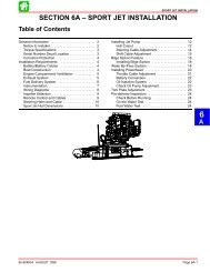
SPORT JET INSTALLATION
SPORT JET INSTALLATION
SPORT JET INSTALLATION

Create successful ePaper yourself
Turn your PDF publications into a flip-book with our unique Google optimized e-Paper software.
Boat Construction<br />
IMPORTANT: All applicable Coast Guard regulations<br />
for INBOARD engines must be complied<br />
with, when constructing engine compartment.<br />
Care must be exercised in the design and construction<br />
of the engine compartment. Seams must be located<br />
so that any rain water or splash, which may leak<br />
through the seams, is directed away from the engine<br />
and carburetor cover. Also, the passenger compartment<br />
drainage system should not be routed directly<br />
to the engine compartment. Water that runs on or is<br />
splashed in the carburetor cover may enter the<br />
engine and cause serious damage to internal engine<br />
parts.<br />
IMPORTANT: Mercury Marine will not honor any<br />
warranty claim for engine damage as a result of<br />
water entry.<br />
Engine Compartment Ventilation<br />
Engine compartment must be designed to provide a<br />
sufficient volume of air for engine breathing and also<br />
must vent off any fumes in engine compartment in<br />
accordance with industry standards (ABYC, NMMA,<br />
etc.), federal standards and Coast Guard regulations<br />
for inboard engines. Pressure differential (outside engine<br />
compartment versus inside engine compartment)<br />
should not exceed 2 in. (51mm) of water (measured<br />
with a manometer) at maximum air flow rate.<br />
Engine Compartment Specifications<br />
Model<br />
90/95<br />
HP<br />
120<br />
HP<br />
Engine Air Requirements<br />
at Wide Open<br />
Throttle<br />
230 ft. 3 /min.<br />
(0.109m 3 /sec.)<br />
304 ft. 3 /min.<br />
(0.143 m 3 /sec.)<br />
Physical Engine<br />
Volume*<br />
0.60 ft. 3<br />
(17 L)<br />
0.67 ft. 3<br />
(19 L)<br />
* Physical engine volume is used in flotation calculations and is<br />
representative of the amount of flotation the engine provides.<br />
For serviceability, it is recommended that an additional<br />
6 inches minimum (152 mm) (per side) of clearance<br />
be allowed between powerhead and engine<br />
compartment walls.<br />
Exhaust System<br />
IMPORTANT: It is the responsibility of the boat<br />
manufacturer, or installing dealer, to properly<br />
locate the engine. Improper installation may<br />
allow water to enter the exhaust manifold and<br />
combustion chambers and severely damage the<br />
engine. Damage caused by water in the engine<br />
will not be covered by Mercury Marine Limited<br />
Warranty, unless this damage is the result of<br />
defective part(s).<br />
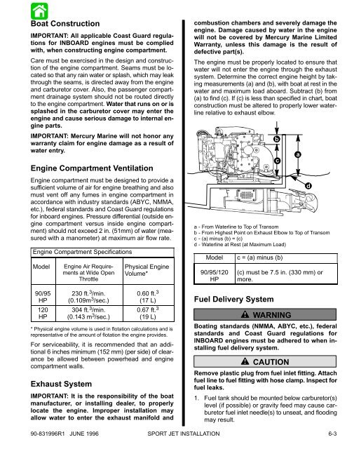
The engine must be properly located to ensure that<br />
water will not enter the engine through the exhaust<br />
system. Determine the correct engine height by taking<br />
measurements (a) and (b), with boat at rest in the<br />
water and maximum load aboard. Subtract (b) from<br />
(a) to find (c). If (c) is less than specified in chart, boat<br />
construction must be altered to properly lower waterline<br />
relative to exhaust elbow.<br />
a - From Waterline to Top of Transom<br />
b - From Highest Point on Exhaust Elbow to Top of Transom<br />
c - (a) minus (b) = (c)<br />
d - Waterline at Rest (at Maximum Load)<br />
Model<br />
90/95/120<br />
HP<br />
b<br />
c<br />
c = (a) minus (b)<br />
Fuel Delivery System<br />
(c) must be 7.5 in. (330 mm) or<br />
more.<br />
! WARNING<br />
Boating standards (NMMA, ABYC, etc.), federal<br />
standards and Coast Guard regulations for<br />
INBOARD engines must be adhered to when installing<br />
fuel delivery system.<br />
! CAUTION<br />
Remove plastic plug from fuel inlet fitting. Attach<br />
fuel line to fuel fitting with hose clamp. Inspect for<br />
fuel leaks.<br />
1. Fuel tank should be mounted below carburetor(s)<br />
level (if possible) or gravity feed may cause carburetor<br />
fuel inlet needle(s) to unseat, and flooding<br />
may result.<br />
a<br />
d<br />
90-831996R1 JUNE 1996 <strong>SPORT</strong> <strong>JET</strong> <strong>INSTALLATION</strong><br />
6-3