SPORT JET INSTALLATION
SPORT JET INSTALLATION
SPORT JET INSTALLATION

You also want an ePaper? Increase the reach of your titles
YUMPU automatically turns print PDFs into web optimized ePapers that Google loves.
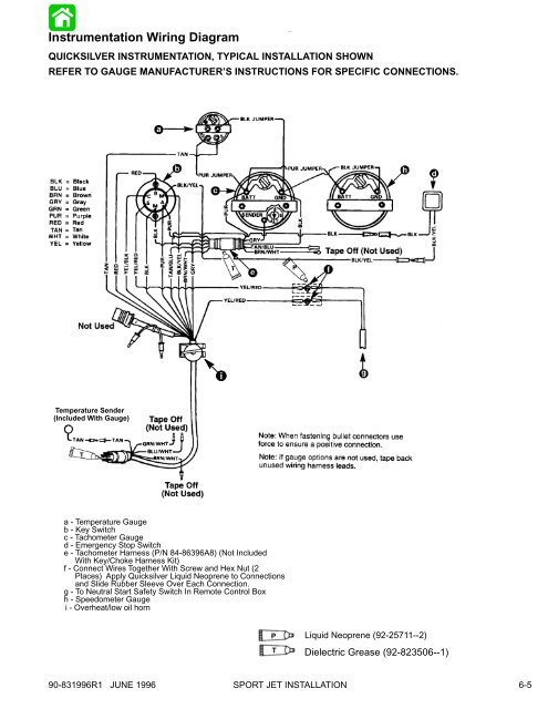
Instrumentation Wiring Diagram<br />
QUICKSILVER INSTRUMENTATION, TYPICAL <strong>INSTALLATION</strong> SHOWN<br />
REFER TO GAUGE MANUFACTURER’S INSTRUCTIONS FOR SPECIFIC CONNECTIONS.<br />
i<br />
Temperature Sender<br />
(Included With Gauge)<br />
a - Temperature Gauge<br />
b - Key Switch<br />
c - Tachometer Gauge<br />
d - Emergency Stop Switch<br />
e - Tachometer Harness (P/N 84-86396A8) (Not Included<br />
With Key/Choke Harness Kit)<br />
f - Connect Wires Together With Screw and Hex Nut (2<br />
Places) Apply Quicksilver Liquid Neoprene to Connections<br />
and Slide Rubber Sleeve Over Each Connection.<br />
g - To Neutral Start Safety Switch In Remote Control Box<br />
h - Speedometer Gauge<br />
i - Overheat/low oil horn<br />
P<br />
T<br />
Liquid Neoprene (92-25711--2)<br />
Dielectric Grease (92-823506--1)<br />
90-831996R1 JUNE 1996 <strong>SPORT</strong> <strong>JET</strong> <strong>INSTALLATION</strong><br />
6-5