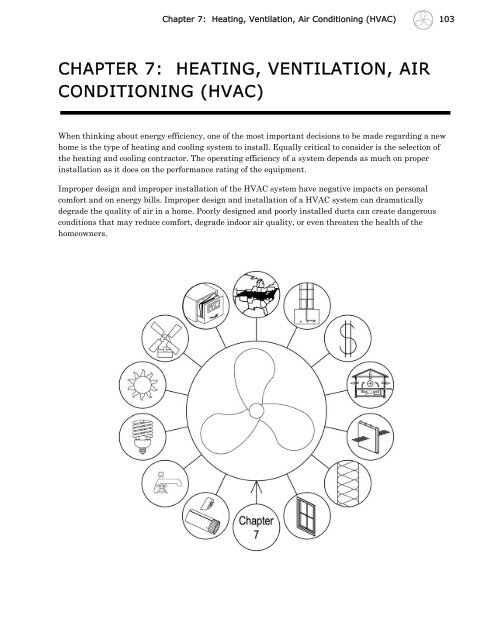
CHAPTER 7: HEATING, VENTILATION, AIR CONDITIONING (HVAC)
CHAPTER 7: HEATING, VENTILATION, AIR CONDITIONING (HVAC)
CHAPTER 7: HEATING, VENTILATION, AIR CONDITIONING (HVAC)

Create successful ePaper yourself
Turn your PDF publications into a flip-book with our unique Google optimized e-Paper software.
Chapter 7: Heating, Ventilation, Air Conditioning (<strong>HVAC</strong>) 103<br />
<strong>CHAPTER</strong> 7: <strong>HEATING</strong>, <strong>VENTILATION</strong>, <strong>AIR</strong><br />
<strong>CONDITIONING</strong> (<strong>HVAC</strong>)<br />
When thinking about energy efficiency, one of the most important decisions to be made regarding a new<br />
home is the type of heating and cooling system to install. Equally critical to consider is the selection of<br />
the heating and cooling contractor. The operating efficiency of a system depends as much on proper<br />
installation as it does on the performance rating of the equipment.<br />
Improper design and improper installation of the <strong>HVAC</strong> system have negative impacts on personal<br />
comfort and on energy bills. Improper design and installation of a <strong>HVAC</strong> system can dramatically<br />
degrade the quality of air in a home. Poorly designed and poorly installed ducts can create dangerous<br />
conditions that may reduce comfort, degrade indoor air quality, or even threaten the health of the<br />
homeowners.
104 Chapter 7: Heating, Ventilation, Air Conditioning (<strong>HVAC</strong>)<br />
TYPES OF <strong>HEATING</strong> SYSTEMS<br />
Keys to obtaining design efficiency of a system in the field include:<br />
<br />
<br />
<br />
<br />
<br />
Sizing the system for the specific heating and cooling load of the home being built;<br />
Proper selection and proper installation of controls;<br />
Correctly charging the unit with the proper amount of refrigerant;<br />
Sizing and designing the layout of the ductwork or piping for maximizing energy efficiency; and<br />
Insulating and sealing all ductwork.<br />
Two types of heating systems are most common in a new home: forced-air or radiant, with forced-air<br />
being used in the majority of the homes. The heat source is either a furnace, which burns a gas, or an<br />
electric heat pump. Furnaces are generally installed with central air conditioners. Heat pumps provide<br />
both heating and cooling. Some heating systems have an integrated water heating system.<br />
FORCED-<strong>AIR</strong> SYSTEM COMPONENTS<br />
Most new homes have forced-air heating and cooling systems. These systems use a central furnace plus<br />
an air conditioner, or a heat pump. Figure 7-1 shows all the components of a forced-air system. In a<br />
typical system, several of these components are combined into one unit. Forced-air systems utilize a<br />
series of ducts to distribute the conditioned heated or cooled air throughout the home. A blower, located<br />
in a unit called an air handler, forces the conditioned air through the ducts. In many residential systems,<br />
the blower is integral with the furnace enclosure.<br />
Figure 7 – 1 Components of Horizontal Flow Forced-Air Systems
Chapter 7: Heating, Ventilation, Air Conditioning (<strong>HVAC</strong>) 105<br />
Most homes in Kentucky have a choice of the following approaches for central, forced-air systems; fuelfired<br />
furnaces with electric air conditioning units, electric heat pumps or a dual fuel system that<br />
combines both a fuel-fired furnace with an electric heat pump. The best system for each home depends on<br />
the cost and efficiency of the equipment, annual energy use, and the local price and availability of energy<br />
sources. In most homes, either type of system, if designed and installed properly, will economically<br />
deliver personal comfort.<br />
RADIANT <strong>HEATING</strong> SYSTEMS<br />
Radiant heating systems typically combine a central boiler, water heater or heat pump water heater with<br />
piping, to transport steam or hot water into the living area. Heating is delivered to the rooms in the home<br />
via radiators or radiant floor systems, such as radiant slabs or underfloor piping.<br />
Advantages of radiant heating systems include:<br />
<br />
<br />
<br />
<br />
Quieter operation than heating systems that use forced-air blowers.<br />
Increased personal comfort at lower air temperatures. The higher radiant temperatures of the<br />
radiators or floors allow people to feel warmer at lower air temperatures. Some homeowners, with<br />
radiant heating systems, report being comfortable at room air temperatures of 60°F.<br />
Better zoning of heat delivered to each room.<br />
Increased comfort from the heat. Many homeowners, with radiant heating systems, find that the<br />
heating is more comfortable.<br />
Disadvantages of radiant heating systems include:<br />
<br />
<br />
<br />
<br />
Higher installation costs. Radiant systems typically cost 40% to 60% more to install than<br />
comparable forced-air heating systems.<br />
No provision for cooling the home. The cost of a radiant heating system, combined with central<br />
cooling, would be difficult to justify economically. Some designers of two-story homes have<br />
specified radiant heating systems on the bottom floor and forced-air heating and cooling on the<br />
second floor.<br />
No filtering of the air. Since the air is not cycled between the system and the house, there is no<br />
filtering of the air.<br />
Difficulty in locating parts. A choice of dealers may be limited.<br />
HEAT PUMP EQUIPMENT<br />
Heat pumps are designed to move heat from one fluid to another. The fluid inside the home is air and the<br />
fluid outside is either air (air-source), or water (geothermal). In the summer, heat from the inside air is<br />
moved to the outside fluid. In the winter, heat is taken from the outside fluid and moved to the inside air.<br />
<strong>AIR</strong>-SOURCE HEAT PUMPS<br />
The most common type of heat pump is the air-source heat pump. Most heat pumps operate at least twice<br />
as efficiently as conventional electric resistance heating systems in Climate Zone 4. They have typical<br />
lifetimes of 15 years, compared to 20 years for most furnaces.
106 Chapter 7: Heating, Ventilation, Air Conditioning (<strong>HVAC</strong>)<br />
Heat pumps use the vapor compression cycle to move heat (see Figure 7-2). A reversing valve allows the<br />
heat pump to work automatically in either heating or cooling mode. The heating process is:<br />
1. The compressor (in the outside unit) pressurizes the refrigerant, which is piped inside.<br />
2. The hot gas enters the inside condensing coil. Room air passes over the coil and is heated. The<br />
refrigerant cools and condenses.<br />
3. The refrigerant, now a pressurized liquid, flows outside to a throttling valve where it<br />
expands to become a cool, low pressure liquid.<br />
4. The outdoor evaporator coil, which serves as the condenser in the cooling process, uses<br />
outside air to boil the cold, liquid refrigerant into a gas. This step completes the cycle.<br />
5. If the outdoor air is so cold that the heat pump cannot adequately heat the home, electric<br />
resistance strip heaters usually provide supplemental heating.<br />
Periodically in winter, the heat pump must switch to a "defrost cycle," which melts any ice that has<br />
formed on the outdoor coil. Packaged systems and room units use the above components in a single box.<br />
Figure 7 – 2 Air Conditioner Vapor Compression Cycle<br />
At outside temperatures of 25°F to 35°F, a properly sized heat pump can no longer meet the entire<br />
heating load of the home. The temperature at which a properly sized heat pump can no longer meet the<br />
heating load is called the balance point. To provide supplemental backup heat, many builders use electric<br />
resistance coils called strip heaters. The strip heaters, located in the air-handling unit, are much more
Chapter 7: Heating, Ventilation, Air Conditioning (<strong>HVAC</strong>) 107<br />
expensive to operate than the heat pump itself. The strip heaters should not be oversized, as they can<br />
drive up the peak load requirements of the local electric utility.<br />
A staged, heat pump thermostat can be used in concert with multistage strip heaters to minimize strip<br />
heat operation. To overcome this problem, some houses use a dual-fuel system that heats the home with<br />
natural gas or propane when temperatures drop below the balance point.<br />
Air-source heat pumps should have outdoor thermostats, which prevent operation of the strip heaters at<br />
temperatures above 35°F or 40°F. Many mechanical and energy codes require controls to prevent strip<br />
heater operation during weather when the heat pump alone can provide adequate heating.<br />
The proper airflow across the coil is essential for the efficient operation of a heat pump. During<br />
installation, the airflow rate must be checked to ensure that it meets the manufacturer’s<br />
recommendations.<br />
<strong>AIR</strong>-SOURCE HEAT PUMP EFFICIENCY<br />
The heating efficiency of a heat pump is measured by its Heating Season Performance Factor (HSPF),<br />
which is the ratio of heat provided in Btu per hour to watts of energy used. This factor considers the<br />
losses when the equipment starts up and stops, as well as the energy lost during the defrost cycle.<br />
New heat pumps manufactured after 2005 are required to have an HSPF of at least 7.7. Typical values<br />
for the HSPF are 7.7 for minimum efficiency, 8.0 for medium efficiency, and 8.2 for high efficiency.<br />
Variable speed heat pumps have HSPF ratings as high as 9.0, and geothermal heat pumps have HSPFs<br />
over 10.0. The HSPF averages the performance of heating equipment for a typical winter in the United<br />
States, so the actual efficiency will vary in different climates.<br />
To modify the HSPF for a specific climate, a modeling study was conducted and an equation was<br />
developed that modifies the HSPF, based on the local design winter temperature. In colder climates, the<br />
HSPF declines and in warmer climates, it increases. In Climate Zone 4, the predicted HSPF is<br />
approximately 15% less than the reported HSPF.<br />
GEOTHERMAL HEAT PUMPS<br />
Unlike an air-source heat pump, which has an outside air heat exchanger, a geothermal heat pump relies<br />
on fluid-filled pipes, buried beneath the earth, as a source of heating in winter and cooling in summer,<br />
Figures 7-3, 7-4. In each season, the temperature of the earth is closer to the desired temperature of the<br />
home, so less energy is needed to maintain comfort. Eliminating the outside equipment means higher<br />
efficiency, less maintenance, greater equipment life, no noise, and no inconvenience of having to mow<br />
around that outdoor unit. This is offset by the higher installation cost.
108 Chapter 7: Heating, Ventilation, Air Conditioning (<strong>HVAC</strong>)<br />
Geothermal Heat Pumps<br />
Figure 7 – 3 Deep Well Loop<br />
Figure 7 – 4 Shallow Trench Loop<br />
There are several types of closed loop designs for piping:<br />
<br />
<br />
<br />
In deep well systems, a piping loop extends several hundred feet underground.<br />
Shallow loops are placed in long trenches, typically about 6 feet deep and several hundred feet<br />
long. Coiling the piping into a "slinky" reduces the length requirements.<br />
For homes located on large private lakes, loops can be installed at the bottom of the lake, which<br />
usually decreases the installation costs and may improve performance.<br />
Proper installation of the geothermal loops is essential for high performance and the longevity of the<br />
system. Choose only qualified professionals, who have several years experience installing geothermal<br />
heat pumps similar to that designed for your home.<br />
Geothermal heat pumps provide longer service than air-source units do. The inside equipment should last<br />
as long as any other traditional heating or cooling system. The buried piping usually has a 25-year<br />
warranty. Most experts believe that the piping will last even longer because it is made of a durable<br />
plastic with heat-sealed connections, and the circulating fluid has an anticorrosive additive.<br />
Geothermal heat pumps cost $1,300 to $2,300 more per ton than conventional air-source heat pumps. The<br />
actual cost varies according to the difficulty of installing the ground loops as well as the size and features
Chapter 7: Heating, Ventilation, Air Conditioning (<strong>HVAC</strong>) 109<br />
of the equipment. Because of their high installation cost, these units may not be economical for homes<br />
with low heating and cooling needs. However, their lower operating costs, reduced maintenance<br />
requirements, and greater comfort may make them attractive to many homeowners.<br />
GEOTHERMAL HEAT PUMP EFFICIENCY<br />
The heating efficiency of a geothermal heat pump is measured by the Coefficient of Performance (COP),<br />
which measures the number of units of heating or cooling produced by a unit of electricity. The COP is a<br />
more direct measure of efficiency than the HSPF and is used for geothermal heat pumps because the<br />
water temperature is more constant. Manufacturers of geothermal units provide COPs for different<br />
supply water temperatures. If a unit were installed with a COP of 3.0, the system would be operating at<br />
about 300% efficiency.<br />
FURNACE EQUIPMENT<br />
Furnaces burn fuels such as natural gas, propane, and fuel oil to produce heat and provide warm,<br />
comfortable indoor air during cold weather. Furnaces come in a variety of efficiencies. The comparative<br />
economics between heat pumps and furnaces depend on the type of fuel burned, its price, the home’s<br />
design, and the outdoor climate. Recent energy price increases have improved the economics of more<br />
efficient equipment. However, due to the long-term price uncertainty of different forms of energy, it is<br />
difficult to compare furnaces with various fuel types and heat pumps.<br />
FURNACE OPERATION<br />
Furnaces require oxygen for combustion and extra air to vent exhaust gases. Most furnaces are non-direct<br />
vent units—they use the surrounding air for combustion. Others, known as direct vent or uncoupled<br />
furnaces, bring combustion air into the burner area via sealed inlets that extend to outside air.<br />
Direct vent furnaces can be installed within the conditioned area of a home since they do not rely on<br />
inside air for safe operation. Non-direct vent furnaces must receive adequate outside air for combustion<br />
and exhaust venting. The primary concern with non-direct vent units is that a malfunctioning heater<br />
may allow flue gases, which could contain poisonous carbon monoxide, into the area around the furnace.<br />
If there are leaks in the return system, or air leaks between the furnace area and living space, carbon<br />
monoxide could enter habitable areas and cause severe health problems.<br />
Most new furnaces have forced draft exhaust systems, meaning a blower propels exhaust gases out the<br />
flue to the outdoors. Atmospheric furnaces, which have no forced draft fan, are not as common due to<br />
federal efficiency requirements. However, some furnace manufacturers have been able to meet the<br />
efficiency requirements with atmospheric units. Atmospheric furnaces should be isolated from the<br />
conditioned space. Those units located in well ventilated crawl spaces and attics usually have plenty of<br />
combustion air and encounter no problem venting exhaust gases to the outside.<br />
However, units located in closets or mechanical rooms inside the home, or in relatively tight crawl spaces<br />
and basements, may have problems. Furnace mechanical rooms must be well sealed from the other rooms<br />
of the home (see Figure 7-5). The walls, both interior and exterior, should be insulated. Two outside-air<br />
ducts sized for the specific furnace should be installed from outside into the room, one opening near the<br />
floor and another near the ceiling, or as otherwise specified in your locality’s gas code.
110 Chapter 7: Heating, Ventilation, Air Conditioning (<strong>HVAC</strong>)<br />
MEASURES OF EFFICIENCY FOR FURNACES<br />
The efficiency of a gas furnace is measured by the Annual Fuel Utilization Efficiency (AFUE), a rating<br />
that takes into consideration losses from pilot lights, start-up, and stopping. The minimum AFUE for<br />
most furnaces is now 78%, with efficiencies ranging up to 97% for furnaces with condensing heat<br />
exchangers. The AFUE does not consider the unit’s electricity use for fans and blowers, which can easily<br />
exceed $50 annually. An AFUE rating of 78% means that for every $1.00 worth of fuel used by the unit,<br />
approximately $.78 worth of usable heat is produced. The remaining $.22 worth of energy is lost as waste<br />
heat and exhaust up the flue. Efficiency is highest if the furnace operates for longer periods. Oversized<br />
units run intermittently and have reduced operating efficiencies.<br />
Furnaces with AFUEs of 78% to 87% include components such as electronic ignitions, efficient heat<br />
exchangers, better intake air controls, and induced draft blowers to exhaust combustion products. Models<br />
with efficiencies over 90%, commonly called condensing furnaces, include special secondary heat<br />
exchangers that actually cool flue gases until they partially condense, so that heat losses up the exhaust<br />
pipe are virtually eliminated.
Chapter 7: Heating, Ventilation, Air Conditioning (<strong>HVAC</strong>) 111<br />
A drain line must be connected to the flue to catch condensate. One advantage of the cooler exhaust gas is<br />
that the flue can be made of plastic pipe rather than metal and can be vented horizontally through a side<br />
wall.<br />
There are a variety of condensing furnaces available. Some rely primarily on the secondary heat<br />
exchanger to increase efficiency, while others, such as the pulse furnace, have revamped the entire<br />
combustion process.<br />
A pulse furnace achieves efficiencies over 90% using a spark plug to explode gases, sending a shock wave<br />
out an exhaust tailpipe. The wave creates suction to draw in more gas through one-way flapper valves,<br />
and the process repeats. Once such a furnace warms up, the spark plug is not needed because the heat of<br />
combustion will ignite the next batch of gas. The biggest problem is noise, so make sure the furnace is<br />
supplied with a good muffler, and do not install the exhaust pipe where any noise will be annoying.<br />
Because of the wide variety of condensing furnaces on the market, compare prices, warranties, and<br />
service. Also, compare the economics carefully with those of moderate efficiency units. Condensing units<br />
may have longer paybacks than expected for energy efficient homes due to reduced heating loads. Table<br />
7-1 compares the break-even investment for high efficiency gas furnaces in Code and in ENERGY STAR ®<br />
homes.<br />
Table 7-1 Economic Analysis of Gas Furnaces<br />
Type of Treatment<br />
AFUE 0.95<br />
Energy Savings*($/yr)<br />
Compared to AFUE 0.80<br />
Break-even Investment‡ ($)<br />
Code Home 42 477<br />
ENERGY STAR ® Home 31 352<br />
*For a system in Lexington, KY<br />
‡See Chapter 2 for information on break-even investment.<br />
ELECTRIC INTEGRATED SYSTEMS<br />
Several products use central heat pumps for water heating, space heating, and air conditioning. These<br />
integrated units are available in both air-source and geothermal models. To be a viable choice, integrated<br />
systems should:<br />
<br />
<br />
<br />
<br />
Have a proven track record in the field;<br />
Cost about the same, if not less, than comparable separate heating and hot water systems;<br />
Provide at least a five-year warranty; and<br />
Be properly sized for both the heating and hot water load.
112 Chapter 7: Heating, Ventilation, Air Conditioning (<strong>HVAC</strong>)<br />
Make sure the unit is not substantially more expensive than a separate energy efficient heat pump and<br />
electric water heater. Units within $1,500 may provide favorable economic returns.<br />
UNVENTED FUEL-FIRED HEATERS<br />
Unvented heaters that burn natural gas, propane, kerosene, or other fuels are not recommended. While<br />
these devices usually operate without problems, the consequences of a malfunction are life threatening—<br />
they can exhaust carbon monoxide directly into household air. Unvented heaters also can cause serious<br />
moisture problems inside the home.<br />
Most devices come equipped with alarms designed to detect air quality problems. However, many experts<br />
question putting a family at any risk of carbon monoxide poisoning; they see no rationale for bringing<br />
these units into a home (Figure 7-6).<br />
Figure 7-6 Unvented Heater<br />
Examples of unvented units to avoid include:<br />
<br />
<br />
Vent-free gas fireplaces. Use sealed combustion, direct vent units instead.<br />
Room space heaters.<br />
Choose forced draft, direct-vent models instead (Figure 7-7).
Chapter 7: Heating, Ventilation, Air Conditioning (<strong>HVAC</strong>) 113<br />
Figure 7-7 Direct Vent Heater<br />
<strong>AIR</strong> <strong>CONDITIONING</strong><br />
In summer, air conditioners and heat pumps work the same way to provide cooling and dehumidification.<br />
They extract heat from inside the home and transfer it outside. Both systems typically use a vapor<br />
compression cycle. This cycle circulates a refrigerant, a material that increases in temperature<br />
significantly when compressed and cools rapidly when expanded. The exterior portion of a typical air<br />
conditioner is called the condensing unit and houses the compressor, the noisy part that uses most of the<br />
energy, and the condensing coil.<br />
An air-cooled condensing unit should be kept free from plants and debris that might block the flow of air<br />
through the coil or damage the thin fins of the coil. Ideally, the condensing unit should be located in the<br />
shade. However, do not block air flow to this unit with dense vegetation, fencing or overhead decking.<br />
The inside mechanical equipment, called the air-handling unit, houses the evaporator coil, the indoor<br />
blower, and the expansion, or throttling valve. The controls and ductwork for circulating cooled air to the<br />
house complete the system.
114 Chapter 7: Heating, Ventilation, Air Conditioning (<strong>HVAC</strong>)<br />
<strong>AIR</strong> CONDITIONERS<br />
Air conditioners use the vapor compression cycle, a 4-step process (see Figure 7-8).<br />
Figure 7-8 Air Conditioner Vapor Compression Cycle<br />
1. The compressor (in the outside unit) pressurizes a gaseous refrigerant. The refrigerant<br />
heats up during this process.<br />
2. Fans in the outdoor unit blow air across the heated, pressurized gas in the condensing<br />
coil; the refrigerant gas cools and condenses into a liquid.<br />
3. The pressurized liquid is piped inside to the air-handling unit. It enters a throttling or<br />
expansion valve, where it expands and cools.<br />
4. The cold liquid circulates through evaporator coils. Inside air is blown across the coils and<br />
cooled while the refrigerant warms and evaporates. The cooled air is blown through the<br />
ductwork. The refrigerant, now a gas, returns to the outdoor unit where the process<br />
repeats.<br />
If units are not providing sufficient dehumidification, the typical homeowner’s response is to lower the<br />
thermostat setting. Since every degree the thermostat is lowered increases cooling bills 3% to 7%,<br />
systems that have nominally high efficiencies, but inadequate dehumidification, may suffer from higher<br />
than expected cooling bills. In fact, poorly functioning "high" efficiency systems may actually cost more to<br />
operate than a well-designed, moderate efficiency unit.
Chapter 7: Heating, Ventilation, Air Conditioning (<strong>HVAC</strong>) 115<br />
Make certain that the contractor has used Manual J techniques to size the system so that the air<br />
conditioning system meets both sensible and latent (humidity) loads at the manufacturer’s claimed<br />
efficiency.<br />
THE SEER RATING<br />
The cooling efficiency of a heat pump or an air conditioner is rated by the Seasonal Energy Efficiency<br />
Ratio (SEER), a ratio of the average amount of cooling provided during the cooling season to the amount<br />
of electricity used. Current national legislation mandates a minimum SEER 13.0 for most residential air<br />
conditioners. Efficiencies of some units can exceed SEER 19.0.<br />
Similar to the HSPF, a modeling study was conducted and an equation was developed that modifies the<br />
SEER, based on the local design summer temperature. In warmer climates, the SEER declines. In<br />
Climate Zone 4, the predicted SEER is approximately 5% less than the reported SEER.<br />
VARIABLE SPEED UNITS<br />
The current minimum standard for air conditioners is SEER 13. Higher efficiency air conditioners may be<br />
quite economical. Table 7-2 examines the economics of different options for a sample home. In order to<br />
increase the overall operating efficiency of an air conditioner or heat pump, multispeed and variable<br />
speed compressors have been developed. These compressor units can operate at low or medium speeds<br />
when the outdoor temperatures are not extreme. They can achieve a SEER of 15 to 17. The cost of<br />
variable speed units is generally about 30% higher than standard units. Variable speed units offer<br />
several advantages over standard, single-speed blowers, such as:<br />
<br />
<br />
<br />
They usually save energy;<br />
They are quieter, and because they operate fairly continuously, start-up noise is far less (often the<br />
most noticeable sound); and<br />
They dehumidify better. Some units offer a special dehumidification cycle, which is triggered by a<br />
humidistat that senses when the humidity levels in the home are too high.<br />
Table 7-2 Air Conditioner Economics<br />
Type of Treatment Energy Savings* ($/yr) Break-even Investment‡ ($)<br />
SEER 14 (3 tons) -<br />
compared to SEER 13<br />
20 227<br />
SEER 15 (3 tons) -<br />
compared to SEER 14<br />
32 363<br />
*For a system in Lexington, KY<br />
‡See Chapter 2 for information on break-even investment.
116 Chapter 7: Heating, Ventilation, Air Conditioning (<strong>HVAC</strong>)<br />
PROPER INSTALLATION<br />
Too often, high efficiency cooling and heating equipment is improperly installed, which can cause it to<br />
operate at a substantially reduced efficiency. A SEER 13 air conditioning system that is installed poorly<br />
with leaky ductwork may operate at 25% to 40% lower efficiency during hot weather. Typical installation<br />
problems are:<br />
<br />
<br />
<br />
Improper charging of the system—the refrigerant of the cooling system is the workhorse—it flows<br />
back and forth between the inside coil and the outside coil, changing states, and undergoing<br />
compression and expansion. A system can have too little or too much refrigerant. The <strong>HVAC</strong><br />
contractor should use the manufacturer’s installation procedures to charge the system properly.<br />
The correct charge cannot be ensured by pressure gauge measurements alone. In new<br />
construction, the refrigerant should be weighed in. Then, use either the supercharge temperature<br />
method or, for certain types of expansion valves, the subcooling method, to confirm that the<br />
charge is correct.<br />
Reduced air flow—if the system has poorly designed ductwork, constrictions in the air<br />
distribution system, clogged or more restrictive filters, or other impediments, the blower may not<br />
be able to transport adequate air over the indoor coils of the cooling system. Reduced air flow of<br />
20% can drop the operating efficiency of the unit by about 1.7 SEER points; thus, a unit with a<br />
SEER 13.0 would only operate at SEER 11.3.<br />
Inadequate air flow to the outdoor unit—if the outdoor unit is located under a deck or within an<br />
enclosure, adequate air circulation between the unit and outdoor air may not occur. In such cases,<br />
the temperature of the air around the unit rises, thereby making it more difficult for the unit to<br />
cool the refrigerant that it is circulating. The efficiency of a unit surrounded by outdoor air that is<br />
10 degrees warmer than the ambient outside temperature can be reduced by over 10%.<br />
<strong>HVAC</strong> SYSTEMS<br />
For proper operation, a <strong>HVAC</strong> system must be properly designed, sized and installed. A proper <strong>HVAC</strong><br />
system will provide an improved indoor environment and minimize the cost of operation. In the planning<br />
process for an energy efficient home, everything should be done to reduce the heating and cooling load on<br />
the home before the <strong>HVAC</strong> system is designed.<br />
SIZING<br />
When considering a <strong>HVAC</strong> system for a residence, remember that energy efficient and passive solar<br />
homes have less demand for heating and cooling. Substantial savings may be obtained by installing<br />
smaller units that are properly sized to meet the load. Because energy bills in more efficient homes are<br />
lower, higher efficiency systems will not provide as much annual savings on energy bills and may not be<br />
as cost effective as in less efficient homes.<br />
Not only does oversized equipment cost more, but also it can waste energy. Oversized equipment may<br />
also decrease comfort. For example, an oversized air conditioner cools a house but may not provide<br />
adequate dehumidification. This cool, but clammy air creates an uncomfortable environment.
Chapter 7: Heating, Ventilation, Air Conditioning (<strong>HVAC</strong>) 117<br />
Do not rely on rule of thumb methods<br />
to size <strong>HVAC</strong> equipment.<br />
Many contractors select air conditioning systems based on a rule, such as 600 square feet of cooled area<br />
per ton of air conditioning (a ton provides 12,000 Btu per hour of cooling). Instead, use a sizing procedure<br />
such as:<br />
<br />
<br />
<br />
Calculations in Manual J published by the Air Conditioning Contractors Association;<br />
Similar procedures developed by the American Society of Heating, Refrigeration, and Air<br />
Conditioning Engineers (ASHRAE); or<br />
Software procedures developed by electric or gas utilities, the U.S. Department of Energy or<br />
<strong>HVAC</strong> equipment manufacturers.<br />
The heating and cooling load calculations rely on the outside winter and summer design temperatures (see<br />
the appendix for a definition) and the size and type of construction for each component of the building<br />
envelope, as well as the heat given off by the lights, people, and equipment inside the house. If a zoned<br />
heating and cooling system is used, the loads in each zone should be calculated. Table 7-3 compares the<br />
size of heating and cooling systems for the homes in Table 2-2. The more efficient home reduces the<br />
heating load 35% and the cooling load 26%. Thus, the $600 to $1,000 savings from reducing the size of the<br />
<strong>HVAC</strong> equipment offset the additional cost of the energy features in the more efficient home.<br />
Type of House<br />
<strong>HVAC</strong> System Sizing<br />
Table 7-3 Equipment Sizing Comparison<br />
Code Home<br />
HERS=98<br />
ENERGY STAR ® Home<br />
HERS=85<br />
Exceeds ENERGY<br />
STAR ® Home<br />
HERS=70<br />
Heating (BTU/hour) 52,200 38,800 25,700<br />
Cooling (BTU/hour) 31,700 25,700 19,800<br />
Estimated tons of cooling* 3.0 2.5 2.0<br />
Square feet/ton 667 800 1,000<br />
*Estimated at 110% of calculated size. There are 12,000 Btu/hour in a ton of cooling.<br />
Oversimplified rules-of-thumb would have provided an oversized heating and cooling system for the more<br />
efficient home. The typical rule-of-thumb in Kentucky has been to allow for 600 square feet per ton of air<br />
conditioning. Since the home has 2,000 square feet of conditioned space, <strong>HVAC</strong> contractors could well
118 Chapter 7: Heating, Ventilation, Air Conditioning (<strong>HVAC</strong>)<br />
provide 3.5 to 4 tons of cooling (2,000 ÷ 600 = 3.33, then round up.) The oversized unit would have cost<br />
more to install. In addition, the operating costs would be higher. The oversized unit would suffer greater<br />
wear and may not provide adequate dehumidification.<br />
Proper sizing includes designing the cooling system to provide adequate dehumidification. In a mixedhumid<br />
climate, it is important to calculate the latent load. The latent load is the amount of<br />
dehumidification needed for the home. If the latent load is ignored, the home may become uncomfortable<br />
due to excess humidity.<br />
The Sensible Heating Fraction (SHF) designates the portion of the cooling load for reducing indoor<br />
temperatures (sensible cooling). For example, in a <strong>HVAC</strong> unit with a 0.75 SHF, 75% of the energy<br />
expended by the unit goes to cool the temperature of indoor air. The remaining 25% goes for latent heat<br />
removal—taking moisture out of the air in the home. To accurately estimate the cooling load, the<br />
designer of a <strong>HVAC</strong> system must also calculate the desired SHF and thus, the latent load.<br />
Many homes in Climate Zone 4 have design SHFs of approximately 0.7. This means that 70% of the<br />
cooling will be sensible and 30% latent. Systems that deliver less than 30% latent cooling may fail to<br />
provide adequate dehumidification in summer. It takes 15 minutes for most air conditioners to reach<br />
peak efficiency. During extreme outside temperatures (under 32°F in winter and over 88°F in summer),<br />
the system should run about 80% of the time. Oversized systems cool the home quickly and often never<br />
reach their peak operating efficiency.<br />
TEMPERATURE CONTROLS<br />
The most basic type of control system is a heating and cooling thermostat. Programmable thermostats,<br />
also called setback thermostats, can be big energy savers for homes. These programmable thermostats<br />
automatically adjust the temperature setting when people are sleeping or are not at home. Be certain<br />
that the programmable thermostat selected is designed for the particular heating and cooling equipment<br />
it will be controlling. This is especially important for heat pumps, as an improper programmable<br />
thermostat can actually increase energy bills.<br />
A thermostat should be located centrally within the house or zone. It should not receive direct sunlight or<br />
be near a heat-producing appliance. A good location is often 4 to 5 feet above the floor in an interior<br />
hallway near a return grille. The interior wall, on which it is installed, should be well sealed at the top<br />
and bottom to prevent circulation of cool air in winter or hot air in summer. Some homeowners have<br />
experienced discomfort and increased energy bills for years because air from the attic leaked into the wall<br />
cavity behind the thermostat and caused the cooling or heating system to run much longer than needed.<br />
ZONED <strong>HVAC</strong> SYSTEMS<br />
Larger homes often use two or more separate heating and air conditioning units for different floors or<br />
areas. Multiple systems can maintain greater comfort throughout the house while saving energy by<br />
allowing different zones of the house to be at different temperatures. The greatest savings come when a<br />
unit serving an unoccupied zone can be turned off.
Chapter 7: Heating, Ventilation, Air Conditioning (<strong>HVAC</strong>) 119<br />
Rather than install two separate systems, <strong>HVAC</strong> contractors can provide automatic zoning systems that<br />
operate with one system. The ductwork in these systems typically has a series of thermostatically<br />
controlled dampers that regulate the flow of air to each zone. Although somewhat new in residential<br />
construction, thermostats, dampers, and controls for zoning large central systems have been used for<br />
years in commercial buildings.<br />
If your heating and air conditioning subcontractors feel that installing two or three separate <strong>HVAC</strong> units<br />
is necessary, have them also estimate the cost of a single system with damper control over the ductwork.<br />
Such a system must be carefully designed to ensure that the blower is not damaged if dampers are closed<br />
to several supply ducts. In this situation, the blower still tries to deliver the same air flow as before, but<br />
now through only a few ducts. Back pressure created against the blades of the blower may cause damage<br />
to the motor. There are three primary design options:<br />
1. Install a manufactured system that uses a dampered bypass duct connecting the supply plenum<br />
to the return ductwork. Installing the bypass damper is the typical approach. When only one zone<br />
is open, the bypass damper, which responds automatically to changes in pressure in the duct<br />
system, will open to allow some of the supply air to take a shortcut directly back to the return,<br />
thus decreasing the overall pressure in the ductwork (Figure 7-9).<br />
2. Create two zones and oversize the ductwork so that when the damper to one zone is closed, the<br />
blower will not suffer damage. This approach is only recommended for two zones of approximately<br />
equal heating and cooling loads.<br />
3. Use a variable speed <strong>HVAC</strong> system with a variable speed fan for the duct system. Because<br />
variable speed systems are usually more efficient than single-speed systems, they will further<br />
increase savings.
120 Chapter 7: Heating, Ventilation, Air Conditioning (<strong>HVAC</strong>)<br />
COOLING EQUIPMENT SELECTION<br />
Tables 7-4 and 7-5 show equipment charts for two sample air conditioning units. Each system provides a<br />
wide range of outputs, depending on the blower speed and the temperature conditions. The SHF (Sensible<br />
Heating Fraction) is the fraction of the total output that cools down the air temperature. The remainder<br />
of the output dehumidifies the air and is the latent cooling. Note that both systems provide about 36,000<br />
Btu/hour of cooling.<br />
Consider System A (Table 7-4) with 80°F return air and SEER 15:<br />
At low fan speed, System A provides 35,800 Btu/hour, 0.71 SHF, and thus 29% latent cooling<br />
(dehumidification).<br />
At high fan speed, System A provides 38,800 Btu/hour, but a 0.81 SHF, and only 19% latent<br />
cooling. This is not enough dehumidification in many Kentucky homes.<br />
Total Air Volume<br />
(cfm)<br />
Table 7-4 Sample Cooling System A Data, SEER 15<br />
Total Cooling<br />
Capacity (Btu/h)<br />
Sensible Heating Fraction (SHF)<br />
Dry Bulb (°F)<br />
75°F 80°F 85°F<br />
950 35,800 0.58 0.71 0.84<br />
1,200 37,500 0.61 0.76 0.91<br />
1,450 38,800 0.64 0.81 0.96<br />
Consider System B (Table 7-5) with 80°F return air and SEER 13:<br />
At low fan speed, System B provides 32,000 Btu/ hour, 0.67 SHF and 33% dehumidification.<br />
At high fan speed, System B provides 35,600 Btu/hour, 0.76 SHF and 24% dehumidification.<br />
Total Air Volume<br />
(cfm)<br />
Table 7-5 Sample Cooling System B Data, SEER 13<br />
Total Cooling<br />
Capacity (Btu/h)<br />
Sensible Heating Fraction (SHF)<br />
Dry Bulb (°F)<br />
75°F 80°F 85°F<br />
950 32,000 0.56 0.67 0.78<br />
1,200 34,100 0.58 0.71 0.84<br />
1,450 35,600 0.61 0.76 0.90<br />
Thus, System A, while nominally more efficient than B, provides less dehumidification<br />
and potentially less comfort.
Chapter 7: Heating, Ventilation, Air Conditioning (<strong>HVAC</strong>) 121<br />
<strong>VENTILATION</strong> AND INDOOR <strong>AIR</strong> QUALITY<br />
All houses need ventilation to remove stale interior air and excessive moisture and to provide oxygen for<br />
the inhabitants. There has been considerable concern recently about how much ventilation is required to<br />
maintain the quality of air in homes. While it is difficult to gauge the severity of indoor air quality<br />
problems, building science experts and most indoor air quality specialists agree that the solution is not to<br />
build an inefficient, “leaky” home.<br />
Research studies show that standard houses are as likely to have indoor air quality problems as energy<br />
efficient ones. While opening and closing windows offers one way to control outside air for ventilation,<br />
this strategy is rarely useful on a regular, year-round basis. Most building researchers believe that no<br />
house is so leaky that the occupants can be relieved of concerns about indoor air quality. The researchers<br />
recommend mechanical ventilation systems for all houses.<br />
The amount of ventilation required depends on the number of occupants and their lifestyle, as well as the<br />
design of the home. The ANSI/ASHRAE standard, “Ventilation and Acceptable Indoor Air Quality in<br />
Low-Rise Residential Buildings” (ANSI/ASHRAE 62.2-2007) recommends that houses have 7.5 natural<br />
cubic feet per minute of fresh air per bedroom + 1, plus additional air flow equal to (in cubic feet per<br />
minute) 1% of the house conditioned area, measured in square feet. In addition, the standard requires<br />
exhaust fans in the kitchen and bathrooms that can be operated when needed.<br />
For example, consider a 2,000 square foot home, with 3 bedrooms, and assume an occupancy of 4 people.<br />
The amount of ventilation recommended by ASHRAE would be 50 cfm:<br />
7.5 cfm x (3 + 1) + 1% x 2,000 = 30 cfm + 20 cfm = 50 cfm<br />
Increasing the number of occupants or increasing the square footage of the home would increase the<br />
necessary ventilation requirements.<br />
Older, drafty houses can have natural air leakage of 1.0 to 2.5 ACHnat. Standard homes built today are<br />
tighter and usually have rates of from 0.35 to 0.75 ACHnat. New, energy efficient homes have rates of<br />
0.30 ACHnat or less. The problem is that air leaks are not a reliable source of fresh air and are not<br />
controllable.<br />
The ENERGY STAR ® rating system includes a consideration of homes that are tightly constructed. If the<br />
home has a measured natural air leakage rate below 0.35 ACHnat, the HERS score will not improve<br />
unless mechanical ventilation is provided. If the measured natural air leakage rate is below 0.25, the<br />
software will provide a warning that additional ventilation air should be provided and the amount<br />
needed.<br />
Air leaks are unpredictable, and leakage rates for all houses vary. For example, air leakage is greater<br />
during cold, windy periods and can be quite low during hot weather. Thus, pollutants may accumulate<br />
during periods of calm weather even in drafty houses. These homes will also have many days when<br />
excessive infiltration provides too much ventilation, causing discomfort, high energy bills, and possible<br />
deterioration of the building envelope.<br />
Concerns about indoor air quality are leading more and more homeowners to install controlled ventilation<br />
systems for providing a reliable source of fresh air. The simplest approach is to provide spot ventilation of<br />
bathrooms and kitchens to control moisture (see Figure 7-10). Nearly all exhaust fans in standard
122 Chapter 7: Heating, Ventilation, Air Conditioning (<strong>HVAC</strong>)<br />
construction are ineffective—a prime contributor to interior moisture problems in homes. Bath and<br />
kitchen exhaust fans should vent to the outside, not just into an attic or crawl space. General guidelines<br />
call for providing a minimum of 50 cubic feet per minute (cfm) of air flow for baths and 100 cfm for<br />
kitchens. Manufacturers should supply a cubic feet per minute (cfm) rating for any exhaust fan.<br />
Figure 7-10 Ventilation with Spot Fan<br />
The cubic feet per minute rating typically assumes the fan is working against an air pressure resistance<br />
of 0.1 inch of water column—the resistance provided by about 15 feet of straight, smooth metal duct. In<br />
practice, most fans are vented with flexible duct that provides much more resistance. Most fans are also<br />
rated at pressures of 0.25 to 0.30 inches of water column—the resistance found in most installations.<br />
While ENERGY STAR ® fans cost more, they are cheaper to operate and are usually better constructed<br />
and therefore, last longer and run quieter. The level of noise for a fan is measured in sones. Choose a fan<br />
with a sone rating of 2.0 or lower. Top quality models are often below 0.5 sones.<br />
Many ceiling- or wall-mounted exhaust fans can be adapted as “in-line” blowers located outside of the<br />
living area, such as in an attic or basement. Manufacturers also offer in-line fans to vent a single bath or<br />
kitchen, or multiple rooms. Distancing the in-line fan, Figure 7-11, from the living area lessens noise<br />
problems.
Chapter 7: Heating, Ventilation, Air Conditioning (<strong>HVAC</strong>) 123<br />
Figure 7-11 In–Line Ventilation with Spot Fan<br />
While improving spot ventilation will certainly help control moisture problems, it may not provide<br />
adequate ventilation for the entire home. A whole house ventilation system can exhaust air from the<br />
kitchen, all baths, the main living area, and bedrooms.<br />
Whole house ventilation systems usually have large single fans located in the attic or basement.<br />
Ductwork extends to rooms requiring ventilation. These units typically have two-speed motors. The low<br />
speed setting gives continuous ventilation—usually 10 cubic feet per minute per person or 0.35 ACH. The<br />
high speed setting can quickly vent moisture or odors.<br />
SUPPLYING OUTSIDE <strong>AIR</strong> FROM <strong>AIR</strong> LEAKS<br />
The air vented from the home by exhaust fans must be replaced by outside air. This new air comes into<br />
the home either through air leakage or through a controlled inlet. Relying on air leaks requires no extra<br />
equipment; however, the occupant has little control over the air entry points. Many of the air leaks come<br />
from undesirable locations, such as crawl spaces or attics. If the home is airtight, the ventilation fans will<br />
not be able to pull in enough outside air to balance the air being exhausted. This generates a negative<br />
pressure in the home, which may cause increased wear on fan motors. In addition, the exhaust fans may<br />
threaten air quality by pulling exhaust gases from flues and chimneys back into the home.
124 Chapter 7: Heating, Ventilation, Air Conditioning (<strong>HVAC</strong>)<br />
SUPPLYING OUTSIDE <strong>AIR</strong> FROM INLET VENTS<br />
Providing fresh outside air through inlet vents is another option. These vents can often be purchased<br />
from energy specialty outlets by mail order. They are usually located in exterior walls. The amount of air<br />
they allow into the home can be controlled manually or by humidity sensors. Locate inlet vents where<br />
they will not create uncomfortable drafts. These inlet vents are often installed in bedroom closets with<br />
louvered doors or high on exterior walls.<br />
SUPPLYING OUTSIDE <strong>AIR</strong> VIA DUCTED MAKE-UP <strong>AIR</strong><br />
Outside air can also be drawn into and distributed through the home via the ducts for a forced-air<br />
heating and cooling system. This type of system usually has an automatically controlled outside air<br />
damper in the return duct system.<br />
The blower for the ventilation system is either the air handler for the heating and cooling system or a<br />
smaller unit that is strictly designed to provide ventilation air. A slight disadvantage of using the <strong>HVAC</strong><br />
blower is that incoming ventilation air may have sufficient velocity to affect comfort during cold weather.<br />
The return ductwork for the heating and cooling system may be connected to a small outside air duct that<br />
has a damper which opens when the ventilation fan operates. The incoming air flow should not adversely<br />
affect comfort. Special controls are available to ensure that the air handler runs a certain percentage of<br />
every hour, thus providing fresh air on a regular basis.<br />
DEHUMIDIFICATION-<strong>VENTILATION</strong> SYSTEMS<br />
Kentucky homes are often more humid than desired. A combined dehumidification-ventilation system can<br />
bring in fresh (but humid outdoor air), remove moisture, and supply it to the home (see Figure 7-12).<br />
These systems can also filter incoming air. These systems require an additional mechanical device. A<br />
dehumidifier must be installed on the air supply duct. This dehumidifier should be designed for the<br />
specific needs of the home.<br />
A well-designed conventional A/C system without outdoor ventilation air should not need supplemental<br />
dehumidification. It is the excess moisture in outdoor ventilation air that may require the special<br />
dehumidification equipment, especially when mild outdoor temperatures do not require the cooling<br />
system to operate many hours per day to maintain the setpoint temperature.
Chapter 7: Heating, Ventilation, Air Conditioning (<strong>HVAC</strong>) 125<br />
Figure 7-12 Fresh Air and Dehumidification Strategies<br />
HEAT RECOVERY VENTILATORS<br />
Air-to-air heat exchangers, or heat recovery ventilators (HRV), typically have separate duct systems that<br />
draw in outside air for ventilation and distribute fresh air throughout the house. Winter heat from stale<br />
room air is “exchanged” for the cooler incoming air. Some models, called enthalpy heat exchangers, can<br />
also recapture cooling energy in summer by exchanging moisture between exhaust and supply air.<br />
While energy experts have questioned the value of the heat saved in Kentucky homes for the $400 to<br />
$1,500 cost for an HRV, recent studies on enthalpy units indicate their dehumidification benefit in
126 Chapter 7: Heating, Ventilation, Air Conditioning (<strong>HVAC</strong>)<br />
summer offers an advantage over ventilation-only systems. The value of any heat recovery ventilation<br />
system should not be determined solely on the cost of recovered energy. The controlled ventilation and<br />
improved quality of the indoor environment must be considered as well.<br />
SAMPLE <strong>VENTILATION</strong> PLANS<br />
Three options for providing a mechanical ventilation system for a home are shown in the following<br />
designs. While providing mechanical ventilation plans is routine for commercial buildings, their use in<br />
homes is just beginning. As a result, few standard designs exist and some time will be needed for them to<br />
be developed for different climates.<br />
DESIGN 1: UPGRADED SPOT EXHAUST <strong>VENTILATION</strong><br />
This relatively simple and inexpensive whole house ventilation system, Figure 7-13, integrates spot<br />
ventilation using bathroom and kitchen exhaust fans with an upgraded exhaust fan (usually 100 to 150<br />
cfm) in a centrally located bathroom. When the fan operates, outside air is drawn through inlets in closets<br />
with louvered doors. A timer, set to provide ventilation at regular intervals, controls the fan. Interior<br />
doors are undercut to allow air flow to the central exhaust fan. The fan must be a long-life, high-quality<br />
unit that operates quietly. In addition to the automatic ventilation provided by this system, occupants<br />
can turn on all exhaust fans manually as needed.<br />
Figure 7-13 Upgraded Spot Exhaust Ventilation
Chapter 7: Heating, Ventilation, Air Conditioning (<strong>HVAC</strong>) 127<br />
DESIGN 2: WHOLE HOUSE <strong>VENTILATION</strong> SYSTEM<br />
This whole house ventilation system uses a centralized two-speed exhaust fan to draw air from the<br />
kitchen, bath, laundry, and living areas. A timer controls the blower. The system should provide<br />
approximately 0.35 natural air changes per hour (ACHnat) on low speed and 1.0 ACHnat on high speed.<br />
A separate dampered duct connected to the return air system supplies outside air. When the exhaust fan<br />
operates, Figure 7-14, the outside air damper opens and allows air to be drawn into the house through<br />
the forced-air ductwork.<br />
Figure 7-14 Whole House Ventilation System
128 Chapter 7: Heating, Ventilation, Air Conditioning (<strong>HVAC</strong>)<br />
DESIGN 3: HEAT RECOVERY <strong>VENTILATION</strong> (HRV) SYSTEM<br />
An enthalpy recovery ventilator draws fresh outside air through a duct into the heat exchange equipment<br />
and recaptures heating or cooling energy from stale room air as it is being exhausted (see Figure 7-15).<br />
The system also dries incoming humid air in summer. This is a particular benefit in the Southeast. Fresh<br />
air flows into the house via a separate duct system, which should be sealed as tightly as the <strong>HVAC</strong><br />
ductwork. Room air can either be ducted to the exchanger from several rooms or to a single source. Some<br />
HRV units can be wall-mounted in the living area, while others are designed for utility rooms or<br />
basements.<br />
Figure 7-15 Heat Recovery Ventilation (HRV) System
Chapter 7: Heating, Ventilation, Air Conditioning (<strong>HVAC</strong>) 129<br />
RADON<br />
Radon is a cancer-causing, radioactive gas that is found in soils throughout the United States. Although<br />
you cannot see, smell or taste radon, it can become concentrated at dangerous levels in any building,<br />
including homes, offices, and schools. People are most likely to get the greatest exposure at home because<br />
most time is spent there.<br />
REMOVING RADON<br />
Ventilating under the foundation will help remove radon and other soil gases, such as moisture vapor,<br />
before they have a chance to enter the home. It is more cost-effective to include any radon resistant<br />
techniques while building a home, rather than retrofitting an existing home. A typical installation during<br />
construction will cost the homeowner roughly $50 to $300, whereas retrofitting an existing home can cost<br />
up to $2,000. In addition, no operating costs are associated with this passively vented system. If elevated<br />
radon levels are found in the home, a fan can be added easily to make an active system.<br />
Figure 7-16 shows the basics of radon resistant construction for crawl spaces and slabs/basement<br />
foundation types.<br />
Figure 7-16 Radon Resistant Construction
130 Chapter 7: Heating, Ventilation, Air Conditioning (<strong>HVAC</strong>)<br />
PASSIVE AND ACTIVE RADON RESISTANT CONSTRUCTION<br />
Passive concept: a perforated “T” fitting is attached to a vertical plastic vent stack that penetrates the<br />
roof. The “T” is buried in the gravel under the foundation slab and gases can slowly percolate through the<br />
“T” and out the stack.<br />
Active concept: if unacceptable levels of radon are still present, after checking the radon levels from a<br />
passive system, a fan can be added to generate suction to pull gases out through the stack.<br />
SLAB-ON-GRADE OR BASEMENT<br />
Use a 4 to 6 inch gravel base.<br />
Install continuous layer of 6-mil polyethylene.<br />
Stub in “T” below polyethylene that protrudes through polyethylene and extends above poured<br />
floor height.<br />
Pour slab or basement floor.<br />
Seal slab joints with caulk.<br />
CRAWL SPACE<br />
Install sealed, continuous layer of 6-mil polyethylene.<br />
Install “T” below polyethylene that protrudes through polyethylene.<br />
ALL FOUNDATIONS<br />
Install a vertical 3-inch PVC pipe from the foundation to the roof through an interior wall.<br />
Connect the “T” to the vertical 3-inch PVC pipe for passive mitigation.<br />
Have electrician stub-in junction box in attic.<br />
Label PVC pipe “RADON” so that future plumbing work will not be tied into the stack.<br />
TESTING FOR RADON<br />
After building a radon resistant home, it is still recommended to test the home for elevated radon levels.<br />
Low-cost “do-it-yourself” radon test kits can be obtained through the mail, in hardware stores, and other<br />
retail outlets, and possibly from your local government. If desired, a trained contractor can be hired to do<br />
the testing. Make certain that the contractor is certified by the National Environmental Health<br />
Association (NEHA).<br />
WHAT IF HIGH LEVELS ARE FOUND<br />
With the basics of a radon mitigation system already installed, it is relatively inexpensive and easy to<br />
make the system active. Adding an in-line fan, rated for continuous operation, is a relatively simple<br />
addition that will ensure the safe removal of radon from beneath the home.