Digital Panel Meter K3TS - Omron
Digital Panel Meter K3TS - Omron
Digital Panel Meter K3TS - Omron

You also want an ePaper? Increase the reach of your titles
YUMPU automatically turns print PDFs into web optimized ePapers that Google loves.
9<br />
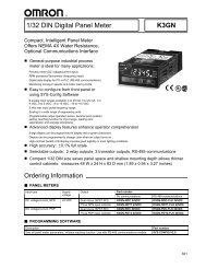
<strong>Digital</strong> <strong>Panel</strong> <strong>Meter</strong><br />
<strong>K3TS</strong><br />
A High-speed Intelligent Signal<br />
Processor Capable of Inspecting<br />
10,000 Objects a Minute<br />
1 Samplingtimeof1.04msandonly5ms<br />
output delay for high speed, high<br />
precision measurement<br />
1 Dual analog inputs with choice of 5<br />
arithmetic functions<br />
1 Up to 5 comparative relay or transistor<br />
outputs available, plus BCD, linear or<br />
communications<br />
1 A wide range of standard features:<br />
sample averaging, output OFF delay,<br />
display refresh period, sensor excitation<br />
and 8 banks of comparative output valves<br />
1 Scaling of signal into relevant<br />
engineering units easily accomplished<br />
through the front panel<br />
1 Four choices of timing signal output<br />
operation (hold, minimum, maximum,<br />
peek and valley)<br />
1 Forced zero function for ease of<br />
calibration in deviation applications<br />
Ordering Information<br />
3 DIGITAL PANEL METER BASE UNITS<br />
Base units Input type Part number<br />
Set value LED model<br />
Process value and set value LED,<br />
front panel membrane switches.<br />
Thumbwheel switches model<br />
Supply voltage<br />
Applicable output boards<br />
100 to 240 VAC 12 to 24 VDC<br />
DC voltage/current <strong>K3TS</strong>-SD11B <strong>K3TS</strong>-SD12B K31-C2/-C5<br />
K31-T1/-T2<br />
K31-B4<br />
K31-L4/-L5/-L6/-L9/-L10<br />
K31-FLK1/-FLK5/-FLK6<br />
DC voltage/current <strong>K3TS</strong>-SD11D <strong>K3TS</strong>-SD12D K31-C1/-C2/-C5<br />
K31-T1/-T2<br />
K31-B4<br />
Process value and set value thumbwheel<br />
switches, front panel membrane<br />
switches.<br />
Note:<br />
“Set Value LED” models must be used with an output board in order for them to operate.<br />
1
<strong>K3TS</strong><br />
<strong>K3TS</strong><br />
3 OUTPUT BOARDS<br />
Output type Output configuration Part number<br />
Comparative relay contact output 3 outputs (H, PASS, L (SPDT) K31-C1<br />
5 outputs: HH, H, L, LL (SPST-NO), and PASS (SPDT) K31-C2<br />
5 outputs: HH, H, L, LL (SPST-NC), and PASS (SPDT) K31-C5<br />
Comparative transistor output 5 outputs (NPN open collector) K31-T1<br />
5 outputs (PNP open collector) K31-T2<br />
BCD output BCD output + 5 transistor outputs (NPN open collector) K31-B4<br />
Linear output 4 to 20 mA + 5 transistor outputs (NPN open collector) K31-L4<br />
1 to 5 V + 5 transistor outputs (NPN open collector) K31-L5<br />
1 mV/digit + 5 transistor outputs (NPN open collector) K31-L6<br />
0to5V<br />
0to10V<br />
K31-L7<br />
K31-L8<br />
0 to 5 V + 5 transistor outputs (NPN open collector) K31-L9<br />
0 to 10 V + 5 transistor outputs (NPN open collector) K31-L10<br />
Communication unit* RS-232C K31-FLK1<br />
RS-485 + 5 transistor outputs (NPN open collector)<br />
RS-422 + 5 transistor outputs (NPN open collector)<br />
*For details, refer to “<strong>K3TS</strong> Communication Output-type Intelligent Signal Processor Operation Manual”.<br />
K31-FLK5<br />
K31-FLK6<br />
2
<strong>K3TS</strong><br />
<strong>K3TS</strong><br />
3 PROTECTIVE COVERS (ORDER SEPARATELY)<br />
The <strong>Panel</strong> <strong>Meter</strong> does not have a water-resistive structure preventing the internal circuitry from drops of water that may penetrate through<br />
the space between the keys and operating panel. If operated by wet or oily hand, put a soft cover K32-49S (sold separately) onto the<br />
operating panel. Although the soft cover corresponds to IP51, use the watertight cover Y92A-49N where the <strong>Panel</strong> <strong>Meter</strong> is directly exposed<br />
to water or oil.<br />
Description Appearance Part number<br />
Transparent, soft front cover which protects the Set<br />
Value LED panel meter from oil and water. All keys on<br />
the front panel can be operated with the cover on. It<br />
meets IP51 only.<br />
<strong>K3TS</strong><br />
K32-49SC<br />
Watertight cover meets NEMA 4 requirements for<br />
hose-down protection. Hinged cover is 94V-2<br />
polycarbonate, packing is chloroprene rubber and<br />
base panel is 304 stainless steel.<br />
Front cover<br />
Y92A-49N<br />
Front cover<br />
3 MODEL NUMBER LEGEND<br />
<strong>K3TS</strong> -<br />
1 2 3 4 5<br />
1, 2. Input Sensors Codes<br />
SD: DC voltage/current input<br />
3. Series No.<br />
1: Standard specifications<br />
2: Forced zero RAM<br />
3: Display shift function<br />
4. Supply Voltage<br />
1: 100 to 240 VAC<br />
2: 12 to 24 VDC<br />
5. Display<br />
B: Set value LED display<br />
D: Thumbwheel switches<br />
3
<strong>K3TS</strong><br />
<strong>K3TS</strong><br />
Specifications<br />
3 RATINGS<br />
Supply voltage<br />
Operating voltage range<br />
Power consumption<br />
Insulation resistance<br />
Dielectric strength<br />
100 to 240 VAC (50/60 Hz); 12 to 24 VDC<br />
85% to 110% of supply voltage<br />
15 VA max. (at max. AC load); 10 W max. (at max. DC load)<br />
10 MΩ min. at 500 VDC between external terminal section and housing<br />
2,000 VAC min. for 1 min between external terminal section and housing<br />
Noise immunity<br />
±1,500 V on power supply terminals in normal or common mode ±1 µs, 100 ns for<br />
square-wave noise with 1 ns rise<br />
Vibration Malfunction 10 to 55 Hz, 0.5-mm for 10 min each in X, Y, and Z directions<br />
Destruction 10 to 55 Hz, 0.75-mm for 2 hrs each in X, Y, and Z directions<br />
Shock Malfunction 100 m/s 2 (approx. 10G) for 3 times each in X, Y, and Z directions<br />
Destruction 300 m/s 2 (approx. 30G) for 3 times each in X, Y, and Z directions<br />
Ambient temperature Operating -10° to 55°C (14° to 131°F) with no icing<br />
Storage<br />
-20° to 65°C (-4° to 149°F) with no icing<br />
Humidity Operating 35% to 85% RH with no condensation<br />
Ambient atmosphere<br />
Enclosure ratings Front panel IEC IP50<br />
Rear case<br />
Terminals<br />
Must be free of corrosive gas<br />
IEC IP20<br />
IEC IP00<br />
Approvals UL File No. E41515<br />
CSA<br />
File No. LR67027<br />
3 CONTROL OUTPUT BOARD RATINGS<br />
Note:<br />
Output boards which can have combinations of output settings will be denoted by an * after the part number<br />
Relay Contact Outputs<br />
Part number<br />
K31-C1, K31-C2, K31-C5<br />
Rated load Resistive load 5 A at 250 VAC; 5 A at 30 VDC (p.f. = 1)<br />
Inductive load 1.5 A at 250 VAC, 1.5 A at 30 VDC (p.f. = 0.4)<br />
Carry current<br />
5 A max. at COM terminal<br />
Max. contact voltage<br />
380 VAC, 125 VDC<br />
Max. contact current<br />
5 A max. at COM terminal<br />
Max. switching<br />
Resistive load 1,250 VA, 150 W<br />
capacity Inductive load 375 VA, 80 W<br />
Output response ON time 15 ms<br />
OFF time 15 ms<br />
Min. permissible load<br />
10 mA at 5 VDC<br />
Transistor Outputs<br />
Part number<br />
K31-T1, K31-L4*, K31-L5*, K31-L6*, K31-L9*, K31-L10*, K31-T2<br />
K31-B4*, K31-S5*, K31-S6*<br />
Output type NPN open collector PNP open collector<br />
Rated load voltage 12 to 24 VDC, +10%/-15%<br />
Maximum load current<br />
50 mA<br />
Leakage current<br />
100µA max.<br />
Output response time<br />
1msmax.<br />
4
<strong>K3TS</strong><br />
<strong>K3TS</strong><br />
Linear Outputs<br />
Part number K31-L4* K31-L5* K31-L6* K31-L9* K31-L10*<br />
Output capacity 4to20mA 1to5V mV/digit 0to5V 0to10V<br />
Resolution 4,096<br />
Permissible load resistance 600Ω max. 500Ω min. 1KΩ min. 500Ω min. 500Ω min.<br />
BCD Outputs<br />
Part number<br />
K31-B4*<br />
Inputs REQUEST<br />
Input voltage<br />
No-voltage contact input<br />
HOLD<br />
Input current<br />
10 mA<br />
MAX REQ.<br />
MIN REQ.<br />
Operating voltage ON 1.5 V max.<br />
RESET<br />
OFF 3Vmin.<br />
Input response time ON 30 ms<br />
OFF 12 ms<br />
Outputs DATA (4 digits) Rated load voltage 12 to 24 VDC, +10%/-15%<br />
POLARITY<br />
DATA OVERFLOW Max. load current<br />
10 mA<br />
DATA VALID<br />
RUN Leakage current 100µA max.<br />
3 COMMUNICATIONS<br />
Part number K31-FLK1 K31-FLK6 K31-FLK5<br />
Output type RS-232C RS-422 RS-485<br />
Transmission method 4-wire, half-duplex 2-wire, half-duplex<br />
Synchronization method<br />
Start-stop synchronization<br />
Baud rate 1,200/2,400/4,800/9,600/19,200/38,400<br />
Transmission code<br />
ASCII (7-bit)<br />
Communications Writeto<strong>K3TS</strong> Comparative set value, prescaling value, remote/local programming, reset control of<br />
maximum/minimum values, and other setting mode items excluding communications<br />
conditions.<br />
Read from <strong>K3TS</strong> Process value, comparative set value, maximum value, minimum value, model data, error<br />
code, and others.<br />
5
<strong>K3TS</strong><br />
<strong>K3TS</strong><br />
3 CHARACTERISTICS<br />
Input<br />
Input range<br />
A/D conversion method<br />
DC voltage/current<br />
See “Measurement Ranges” table below<br />
Sequential conversion method<br />
Sampling speed<br />
1.04 ms<br />
Display Selectable<br />
Sampling period 0.1/1.0/2.0/3.0/4.0 s<br />
refresh speed<br />
Max. displayed digits 4 digits (±9999)<br />
Display<br />
Polarity display<br />
Zero display<br />
7-segment LED<br />
“--” is displayed automatically when the input signal is negative.<br />
Leading zeros are automatically suppressed.<br />
Scaling function<br />
Programmable with front-panel key inputs (range of display: ±9999 with a decimal position of<br />
10 - 1 to 10 - 3 )<br />
Math operations A, A + B, A -- B, k -- (A + B), (1 -- B/A) x 100, B/A x 100<br />
Operation Normal<br />
<strong>Panel</strong> meter display will update as fast as the inputs are scanned<br />
functions<br />
Hold<br />
Process value held until external source sends signal to update display<br />
External TIMING<br />
Timing input<br />
controls<br />
HOLD<br />
Process value held, maximum/minimum data, peak-to--peak, sampling held<br />
RESET<br />
Maximum/minimum data reset, measurement reset<br />
ZERO<br />
Forced zero<br />
BANK<br />
Selection of one bank out of 8 banks of set values<br />
Comparative output setting<br />
4-stage setting (when a 5-output unit is used);<br />
2-stage setting (when a 3-output unit is used)<br />
Output hysteresis setting<br />
Programmable with front-panel key inputs (1 to 999 digits).<br />
Other functions<br />
Set value protect (for models with comparative outputs only)<br />
Variable linear output range (for models with linear outputs only)<br />
Output Relay contact outputs 5 or 3 outputs<br />
configuration<br />
Transistor outputs NPN open collector<br />
Parallel BCD outputs NPN open collector<br />
Linear output 4to20mA,1to5V,mV/digit<br />
Communication RS-232C, RS-485, RS-422<br />
functions<br />
Delay in Normal<br />
6.24 ms<br />
comparative<br />
outputs HOLD 5.20 ms<br />
Memory protection<br />
Non-volatile memory (EEPROM)<br />
3 MEASUREMENT RANGES<br />
Input type Measurement range Input impedance Accuracy* Instaneous overload<br />
Current 2.40 to 26.00 mA 10 Ω 1-ch. input: ±0.1% reading ±1 digit maximum ±200 mA<br />
Voltage 0.600 to 6.500 V 1MΩ<br />
2-ch. input: ±0.2% reading ±1 digit maximum ±200 V<br />
±9.999 V 1MΩ ±200 V<br />
Note:<br />
Accuracy is measured at 25°C (73°F) ambient temperature, ±5°C (±9°F)<br />
6
<strong>K3TS</strong><br />
<strong>K3TS</strong><br />
Connections<br />
3 EXTERNAL CONNECTION<br />
Base Unit<br />
+12 V<br />
(Max. 80 mA) GND<br />
TIMING<br />
IN<br />
COM<br />
HOLD<br />
ZERO Bank 1 Bank 2 Bank 4<br />
Connecting timing sensor:<br />
ON: Residual voltage must be 3 V max.<br />
OFF: Leakage current must be 1.5 mA max.<br />
Load current: The input device must have a<br />
switching capacity of 20 mA min..<br />
+12V (10)<br />
TIMING IN (12)<br />
+ INB<br />
INA<br />
INPUT 4 to 20 mA<br />
+ -- +<br />
INA<br />
INB<br />
INPUT 1 to 5 V<br />
±9.999 V<br />
--<br />
COM<br />
RESET<br />
Terminals 3, 7, and 11 are isolated from one another.<br />
100 to 240 VAC<br />
12 to 24 VDC<br />
GND (11)<br />
Terminals 11 and 12 should be opened and<br />
closed so that a load current of 5 mA or less<br />
will be easily switched for a non-voltage contact<br />
input.<br />
3 OUTPUT BOARDS<br />
Comparative Relay Contact Output Types<br />
K31-C1<br />
Outputs (5 A max. at 250 VAC)<br />
H PASS L<br />
18 19 20 21 22 23 24 25 26<br />
K31-C2<br />
Outputs (5 A max. at 250 VAC)<br />
H<br />
LL<br />
HH PASS L<br />
18 19 20 21 22 23 24 25 26<br />
K31-C5<br />
H<br />
Outputs (5 A max. at 250 VAC)<br />
HH PASS L<br />
LL<br />
18 19 20 21 22 23 24 25 26<br />
Comparative Transistor Output Type<br />
K31-T1<br />
Outputs (50 mA max. at 12 to 24 VDC)<br />
HH H PASS L LL COM<br />
18 19 20 21 22 23 24 25 26<br />
K31-T2<br />
Outputs (50 mA max. at 12 to 24 VDC)<br />
HH H PASS L LL COM<br />
18 19 20 21 22 23 24 25 26<br />
7
<strong>K3TS</strong><br />
<strong>K3TS</strong><br />
BCD Output Type<br />
K31-B4<br />
(Terminals 32 to 36 are provided only on models with special specifications.)<br />
10 4<br />
4 8<br />
DATA OVERFLOW<br />
DATA VALID<br />
RUN<br />
COMMON<br />
REQUEST<br />
MAX. REQ.<br />
MIN. REQ.<br />
HOLD<br />
RESET<br />
POLARITY<br />
HH<br />
H<br />
PASS<br />
L<br />
LL<br />
COMMON<br />
1 2 4 8 1 2 4 8 1 2 4 8 1 2 4 8 1 2<br />
10 0 10 1 10 2 10 3 10 4<br />
COMMON<br />
Models with a BCD output have an open collector output configuration so that wired-OR connection is possible.<br />
<strong>K3TS</strong><br />
(1)<br />
<strong>K3TS</strong><br />
(2)<br />
<strong>K3TS</strong><br />
(3)<br />
BCD Output Timing Chart<br />
Single Sampling Data Output<br />
REQ.<br />
Max.<br />
Min.<br />
DATA<br />
DATA<br />
VALID<br />
All data “high”<br />
Programmable<br />
controller<br />
DATA (incl. POL and OVER)<br />
and DATA VALID are<br />
wired-OR-processed.<br />
Pulse with a width of no less than<br />
20 ms. (no more than 50 ms.)<br />
Data<br />
30 ms 40 ms<br />
16 ms<br />
All data “high”<br />
Approximately 30 ms after the REQ signal rises, a sample is<br />
taken and the DATA VALID signal is output. Read the data when<br />
the DATA VALID signal is ON.<br />
The DATA VALID signal will turn OFF in 40 ms, and then in 16<br />
ms, the data will go OFF.<br />
REQ.<br />
(1)<br />
REQ.<br />
(2)<br />
REQ.<br />
(3)<br />
DATA<br />
(1) (2) (3)<br />
DATA<br />
VALID<br />
* * *<br />
*The period between the DATA VALID signal and the REQ signal<br />
should be no less than 20 ms max..<br />
Continuous Data Output<br />
REQ.<br />
Max.<br />
Min.<br />
DATA All data “high” Data 1 Data 2<br />
DATA<br />
VALID<br />
30ms<br />
40ms<br />
24ms<br />
64ms<br />
40ms<br />
64ms<br />
24ms<br />
The <strong>K3TS</strong> outputs each measurement on an interval of 64 ms<br />
when a REQ signal is ON continuously.<br />
If the HOLD signal is ON at the moment the DATA output is<br />
switched from data 1 to data 2 or vice versa, the output BCD data<br />
will be either data 1 or data 2 according to the timing of the HOLD<br />
signal. However, output data will be low.<br />
Linear Output Type<br />
K31-L4, L5, L6, L9, L10<br />
(Terminals 21 to 26 are provided only on models with special<br />
specifications.)<br />
Outputs (50 mA max. at 12 to 24 VDC)<br />
+ -- HH H PASS L LL COM<br />
18 19 20 21 22 23 24 25 26<br />
L4:4to20mA<br />
L5:1to5V<br />
L6: mV/digit<br />
L9: 0 to 5 VDC + 5 transistor outputs (NPN)<br />
L10: 0 to 10 VDC + 5 transistor outputs (NPN)<br />
8
<strong>K3TS</strong><br />
<strong>K3TS</strong><br />
Communications Output Type<br />
K31-FLK1<br />
K31-FLK5<br />
(Terminals 21 to 26 are provided only on models with special<br />
specifications.)<br />
TXD<br />
RXD<br />
SG<br />
K31-FLK6<br />
(The right connector is provided only on models with special<br />
specifications)<br />
Terminator<br />
ON Outputs (50 mA max. at 12 to 24 VDC)<br />
RS-485<br />
+ --<br />
OFF<br />
HH H PASS L LL COM<br />
18 19 20 21 22 23 24 25 26<br />
Terminator<br />
ON<br />
OFF<br />
RDB<br />
RDA<br />
SG<br />
SDA<br />
SDB<br />
Output NPN Tr.<br />
(50mAmax.at12to24VDC)<br />
LL<br />
HH<br />
H<br />
COM<br />
PASS<br />
L<br />
D-sub 37P Connectors for BCD output (order<br />
separately)<br />
Plug: XM2A-3701<br />
Hood: XM2S-3711<br />
D-sub 9P connectors for RS-422 output (order<br />
separately)<br />
Plug: XM2A-0901 or XM4A-0921<br />
Hood: XM2S-0911<br />
9
<strong>K3TS</strong><br />
<strong>K3TS</strong><br />
Nomenclature<br />
<strong>K3TS</strong>-SD1PB<br />
4. Comparative output status indicators<br />
5. PV display status indicators<br />
2. PV display<br />
1. Operation keys<br />
7. Bank indicators<br />
3. SV display<br />
6. SV display status<br />
indicators<br />
<strong>K3TS</strong>-SD1PD<br />
4. Comparative output status indicators<br />
9. Unit of measure<br />
5. PV display status indicators<br />
2. PV display<br />
1. Operation keys<br />
8. Thumbwheel switches<br />
9. Unit of measure<br />
Name<br />
1.Operation keys<br />
2.PV display<br />
3.SV display<br />
4.Comparative output status<br />
indicators<br />
5.PV display status indicators<br />
6.SV display status indicators<br />
7.Bank indicators<br />
8.Thumbwheel switches<br />
9.Unit of measure<br />
Functions<br />
See next page.<br />
The main display; used for the process value, maximum value, minimum value,<br />
operations/parameters when setting, and error messages.<br />
Displays the set value; also displays parameters when setting.<br />
Indicate the status of the comparative output.<br />
Indicate the ON/OFF status of the hold input, forced zero, and what value is on the PV display:<br />
maximum or minimum.<br />
Indicates which set value is on the SV display.<br />
Indicate which bank of set values is currently selected.<br />
Used to set and display the set values.<br />
Location for attaching the sticker showing the unit of measure (enclosed).<br />
10
<strong>K3TS</strong><br />
<strong>K3TS</strong><br />
Operation Keys<br />
1<br />
3<br />
2<br />
4<br />
5<br />
No. Name Functions<br />
1 DATA TEACH The process value, maximum value, or minimum value is selected.<br />
Process<br />
value<br />
Maximum<br />
value<br />
Minimum<br />
value<br />
In the setting mode, effects the teaching function. With this function, the set values, prescale values<br />
and output range are set by means of actual input.<br />
2 Display Key The value shown on the SV display changes for models with LED displays. In the setting mode, this key is<br />
used to enable setting or to write set values into memory after selecting the parameter with the Shift Key.<br />
Parameter<br />
display<br />
Setting 1 Setting 2<br />
3 Up Key Used to increment the current digit in the set value by one.<br />
4 Shift Key Used to shift the digit being set.<br />
Used to select parameters within each setting level.<br />
Parameter 1 Parameter 2 Parameter n<br />
5 Level Key Used to enter the setting mode. Used within the setting mode to change setting levels.<br />
Note:<br />
Refer to “<strong>K3TS</strong> Operation Manual” for details.<br />
11
<strong>K3TS</strong><br />
<strong>K3TS</strong><br />
Dimensions<br />
Unit: mm (inch)<br />
90 (3.54)<br />
<strong>Panel</strong> Cutouts<br />
45 (1.78)<br />
+0.8<br />
- 0<br />
+0.8<br />
92 (3.62) 75 min. (2.95)<br />
- 0<br />
120 min. (4.72)<br />
91 (3.58)<br />
48 (1.89) 44 (1.73)<br />
43 (1.69)<br />
96 (3.78) 12<br />
130 (5.12)<br />
(0.47)<br />
12
<strong>K3TS</strong><br />
<strong>K3TS</strong><br />
Operation<br />
3 SETTING MODE LEVELS AND PARAMETERS<br />
The <strong>Digital</strong> <strong>Panel</strong> <strong>Meter</strong> has two main modes: RUN mode for normal operations and setting mode for initial parameter input. The setting<br />
mode is divided into three levels based on frequency of use. Within both of these levels are various parameters that can be set.<br />
Initial setting of parameters thus entails entering the setting mode, shifting to the levels that contain parameters that must be set, selecting<br />
the parameters and writing in the desired set values.<br />
Setting Level Diagram<br />
Setting Level 3<br />
Low<br />
Operating<br />
parameter<br />
1<br />
Operating<br />
parameter<br />
2<br />
Operating<br />
parameter<br />
3<br />
Setting Level 2<br />
Press<br />
1s<br />
Frequency<br />
of use<br />
Press<br />
1s<br />
Input<br />
range<br />
Supply<br />
freq.<br />
Display<br />
refresh<br />
periiod<br />
Baud<br />
rate<br />
Setting level 1<br />
Press<br />
1s<br />
Set<br />
values<br />
Hysteresis<br />
Prescaling<br />
Protect<br />
Press<br />
1s<br />
High<br />
RUN mode<br />
Press<br />
2s<br />
Press<br />
1s<br />
1. Press the Level Key to proceed to setting level 1. Press<br />
the Level Key and Up Key once simultaneously to<br />
proceed to setting level 2 or twice simultaneously to proceed<br />
to setting level 3.<br />
2. Use the Shift Key to find the desired parameter.<br />
3. Press the Display Key to access the parameter.<br />
4. Use the Up Key or Shift Key to input the desired value.<br />
5. Exit the present parameter with the Display Key.<br />
6. Return to the RUN mode with the Level Key or with the<br />
Level and Up Keys pressed simultaneously.<br />
3 SETTING PROCEDURES<br />
The <strong>K3TS</strong> stops operating in the setting mode. There are setting parameters that cannot be set or displayed by some <strong>K3TS</strong> models due<br />
to the differences in the Display Models or Output Models. Refer to the <strong>K3TS</strong> Operation Manual for further information.<br />
Shifting Levels<br />
+<br />
Press 1 s<br />
Press 2 s<br />
+<br />
Press 1 s<br />
+<br />
Press 1 s<br />
RUN mode Setting level 1 Setting level 2<br />
Setting level 3<br />
Press 1 s<br />
Press 1 s<br />
13
<strong>K3TS</strong><br />
<strong>K3TS</strong><br />
Setting Level 1<br />
Bank 0<br />
set value<br />
ä,-ö<br />
Bank 7<br />
set value<br />
ä,-ï<br />
Hysteresis<br />
!1,<br />
Prescale<br />
,äæ%<br />
K constant<br />
$,â-<br />
Linear output<br />
range<br />
%,â-<br />
Protect<br />
)+(-<br />
HH, H, L,<br />
and LL of<br />
Bank 0 are<br />
set and writteninsequence<br />
with<br />
the Level<br />
Key (the indicators<br />
for<br />
HH through<br />
LL will be<br />
lit).<br />
The values of<br />
Bank 7 are set<br />
in the same<br />
way the values<br />
of Bank 0 are<br />
set.<br />
Set the<br />
hysteresis<br />
ööõ to ííí<br />
The prescale<br />
value<br />
and input<br />
value for<br />
X2 are set<br />
(the X2 indicator<br />
is<br />
lit).<br />
Set the K<br />
constant<br />
öööö to íííí<br />
The process<br />
value corresponding<br />
to<br />
the maximum<br />
output<br />
(20 mA or 5<br />
V) is set (the<br />
H indicator is<br />
lit).<br />
The alteration<br />
of set values<br />
in the RUN<br />
mode is prohibited.<br />
(áá =Alteration<br />
possible<br />
(' = Alteration<br />
prohibited<br />
Y2 (the process<br />
value for<br />
the X2 input)<br />
is set (the Y2<br />
indicator is lit).<br />
The process<br />
value corresponding<br />
to<br />
the minimum<br />
output (4 mA<br />
or 1 V) is set<br />
(the L indicator<br />
is lit).<br />
X1 and Y1<br />
are set in<br />
the same<br />
way.<br />
The decimal<br />
position is set.<br />
Setting Level 2<br />
Input<br />
range<br />
"'<br />
Display refresh<br />
period<br />
ã",)<br />
No.ofprocess<br />
values to average<br />
æçâ<br />
TIMING-delay<br />
-øã<br />
OFF-delay<br />
(áøã<br />
Communication<br />
unit No.<br />
.ø'(<br />
Baud rate<br />
å),<br />
Select the<br />
input range<br />
òøôö: 4to<br />
20 mA<br />
õø ñ: 1to5V<br />
í÷ííí:<br />
.9.999 V<br />
Select the<br />
display refresh<br />
period<br />
áæ,-: 0.1s<br />
õ: 1s<br />
ô: 2s<br />
ó: 3s<br />
ò: 4s<br />
Select the No.<br />
of precess<br />
values to average<br />
õ: 1times<br />
ô: 2times<br />
ò: 4times<br />
to<br />
îõíô:<br />
8,192 times<br />
Set the<br />
TIMING-delay<br />
ö÷öö to õ÷íí s<br />
Set the OFFdelay<br />
time<br />
ö÷öö to õ÷íí s<br />
Set the unit<br />
number for<br />
the host.<br />
öö to íí<br />
Select the<br />
baud rate<br />
óöö: 300 bps<br />
to<br />
óî÷ò:<br />
38.4 k bps<br />
Setting Level 3<br />
Operating parameter 1<br />
á.'õ<br />
Operating parameter 2<br />
á.'ô<br />
Operating parameter 3<br />
á.'ó<br />
Set the parameter.<br />
æ: A only<br />
æå: A+B<br />
æøå: A--B<br />
$ø æå: k--(A+B)<br />
õø å/æ: 1 -- B/(A) x 100<br />
å/æ: B/A x 100<br />
Set previous average comparison.<br />
(': Used<br />
(ááì Not used<br />
Set the HOLD parameter.<br />
'(+&: Normal<br />
, 0 !: Sampling hold<br />
) 0 !: Maximum hold<br />
å 0 !: Minimum hold<br />
)) 0 !: Peak-to-peak hold<br />
14
<strong>K3TS</strong><br />
<strong>K3TS</strong><br />
3 PARAMETERS<br />
ä,-ö to ï (not provided on Thumbwheel Switches Models)<br />
Set values on each bank can be set with Up Key and Shift Key.<br />
The HH, H, L, or LL comparative output status turns ON when<br />
the measured value exceeds the HH or H set value or falls below<br />
the L or LL set value. The available setting range is between<br />
øíííí to íííí.<br />
The HH and H comparative output status values are set to íííí<br />
and the L and LL comparative output status values are set to<br />
øíííí before shipment.<br />
!1,<br />
The hysteresis of comparative outputs can be set with Up Key<br />
and Shift Key. The available setting range is between ööõ and<br />
ííí1 The hysteresis is set to ööõ before shipment.<br />
,äæ%<br />
Prescale values X2, Y2, X1, and Y1 can be set with Up Key and<br />
Shift Key.<br />
X2: Any input value<br />
Y2: The displayed value corresponding to X2<br />
X1: Any input value<br />
Y1: The displayed value corresponding to X1<br />
Set so that X2 is larger than X1. Y1 can be either smaller or<br />
larger than Y2.<br />
X2 and Y2 are set to ôööö (20.00 mA) and X1 and Y1 are set to<br />
òöö (4.00 mA) before shipment.<br />
Displayed value<br />
$,â-<br />
Y2<br />
Y1<br />
X1<br />
Input value<br />
X2<br />
Displayed value<br />
Y2<br />
Y1<br />
X1<br />
Input value<br />
Set K constant in the parameter, K -- (A + B), with Up Key and<br />
Shift Key. The available setting range is between öööö and íííí1<br />
K constant is set to öööö before shipment.<br />
%,â- (Special linear output model only)<br />
A linear output range can be set as required. A value<br />
corresponding to the L H maximum output value (20 mA or 5 V)<br />
and that corresponding to the L L minimum output value (4 mA or<br />
1 V) can be set with the Up Key and Shift Key. The available<br />
setting range is between øíííí and íííí1 The L H value is set to<br />
íííí and the L L value is set to øíííí before shipment.<br />
Input<br />
20 mA<br />
(5 V)<br />
4mA<br />
(1 V)<br />
L L<br />
L H<br />
Display<br />
X2<br />
)+(- (excluding the Thumbwheel Switches Models)<br />
ThesetvalueprotectcanbeONandOFFusingtheUpKeyin<br />
the RUN mode. (' = Protected, (áá = Not protected. (áá is set<br />
before shipment.<br />
"'<br />
The input range (ò to ôö (4 to 20 mA), õ to ñ (1 to 5 V), and í÷ííí<br />
= .9.999) can be selected with the Up Key. The 4 to<br />
20 mA range is set before shipment.<br />
ã",)<br />
A display refresh period among five levels, áæ,- (every 0.1 s),<br />
õ (every 1 s), ô (every 2 s), ó (every 3 s), and ò (every 4 s), can<br />
be selected with the Up Key. The áæ,- level is selected before<br />
shipment.<br />
æçâ<br />
The number of process values to be averaged (õ to îõíô, on14<br />
different levels ) can be selected with the Up Key. A value of î<br />
level is set before shipment.<br />
-øã<br />
TIMING-delay time (the period required for the <strong>K3TS</strong> to accept<br />
the TIMING signal after it is ON) can be set with the Up Key and<br />
Shift Key. The available setting range is between ö÷öö and õ÷íí1<br />
Atimeofö÷öö is set before shipment.<br />
(áøã<br />
Output OFF-delay time can be set with the Up Key and Shift Key.<br />
The available setting range is ö÷öö to õ÷íí1 Thetimeissettoö÷öö<br />
before shipment.<br />
.ø'( (Communications Output Models)<br />
A unit number, an identification number by which the host<br />
computer identifies each <strong>K3TS</strong> Intelligent Signal Processor, can<br />
be selected with Up Key and Shift Key. The available setting<br />
range is öö to íí1 A value of öö is set before shipment.<br />
å), (Communications Output Models)<br />
A baud rate up to 38,400 bps can be selected with the Up Key.<br />
The available setting range is óöö to óî÷ò$ A value of íðöö is set<br />
before shipment.<br />
á.'õ<br />
Operating parameter 1 can be set to one of the following:<br />
æ: A only; æå: A+B;æø å: A--B;$øæå: k -- (A + B);<br />
õøå æ: 1 -- B/(A) x 100; or å æ: B/A x 100.<br />
D is set before shipment.<br />
á.'ô<br />
Previous average value comparison (operating parameter 2) can<br />
be turned ON and OFF with the Up Key ((' = Possible, (áá =Not<br />
possible). (áá is set before shipment.<br />
á.'ó<br />
The holding data parameter can be set to one of the following:<br />
'(+& (Normal), ,ø! (Sampling hold), )ø! (Peak hold), åø!<br />
(Bottom hold), or ))ø! (Peak-to-peak hold) with the Up Key. '(+&<br />
is set before shipment.<br />
• Verify that panel thickness is 1 to 3.2 mm (0.04 to 0.13 in).<br />
15
<strong>K3TS</strong><br />
<strong>K3TS</strong><br />
NOTE: DIMENSIONS SHOWN ARE IN MILLIMETERS. To convert millimeters to inches divide by 25.4.<br />
9<br />
OMRON ELECTRONICS, INC.<br />
OneEastCommerceDrive<br />
Schaumburg, IL 60173<br />
1-800-55-OMRON<br />
OMRON CANADA, INC.<br />
885 Milner Avenue<br />
Scarborough, Ontario M1B 5V8<br />
416-286-6465<br />
Cat. No. GC IPM6 11/99 Specifications subject to change without notice. Printed in U.S.A.