Diaphragm Accumulators - Airline Hydraulics
Diaphragm Accumulators - Airline Hydraulics
Diaphragm Accumulators - Airline Hydraulics

Create successful ePaper yourself
Turn your PDF publications into a flip-book with our unique Google optimized e-Paper software.
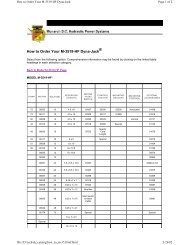
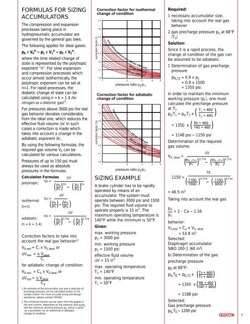
FORMULAS FOR SIZING<br />
ACCUMULATORS<br />
The compression and expansion<br />
processes taking place in<br />
hydropneumatic accumulator are<br />
governed by the general gas laws.<br />
The following applies for ideal gases:<br />
p 0 x V n 0 = p 1 x V n 1 = p 2 x V n 2 ,<br />
where the time related change of<br />
state is represented by the polytropic<br />
exponent “n”. For slow expansion<br />
and compression processes which<br />
occur almost isothermically, the<br />
polytropic exponent can be set at<br />
n=1. For rapid processes, the<br />
diabetic change of state can be<br />
calculated using n = k = 1.4 (for<br />
nitrogen as a diatomic gas) (1 .<br />
For pressures above 3000 psi the real<br />
gas behavior deviates considerably<br />
from the ideal one, which reduces the<br />
effective fluid volume ∆V. In such<br />
cases a correction is made which<br />
takes into account a change in the<br />
adiabatic exponent (k).<br />
By using the following formulas, the<br />
required gas volume V 0 can be<br />
calculated for various calculations.<br />
Pressures of up to 150 psi must<br />
always be used as absolute<br />
pressures in the formulas.<br />
Calculation Formulas ∆V<br />
V0<br />
polytropic:<br />
=<br />
isothermal:<br />
(n=1)<br />
adiabatic:<br />
(n = k = 1.4)<br />
V0 =<br />
P0<br />
P1<br />
V0 =<br />
( ) ( )<br />
P0<br />
P1<br />
∆V<br />
( ) ( )<br />
1/n 1/n<br />
P0<br />
P2<br />
P0<br />
P2<br />
∆V<br />
( ) ( )<br />
P0<br />
P1<br />
0.714<br />
P0<br />
0.714<br />
P2<br />
Correction factors to take into<br />
account the real gas behavior (2<br />
V 0,real = C i x V 0,ideal or<br />
∆V real = ∆ V ideal<br />
C i<br />
for adiabatic change of condition:<br />
V 0,real = C a x V 0,ideal or<br />
∆V real = ∆ V ideal<br />
C a<br />
1 An estimate of the accumulator size and a selection of<br />
precharge pressure can be calculated similar to the<br />
sample shown. For more accurate sizing and design<br />
assistance, please contact HYDAC.<br />
2 The correction factors can be taken from the graphs in<br />
the next column, depending on the pressure ratio p 2 /p 1<br />
and the maximum working pressure p 2 , which is given<br />
as a parameter, for an isothermal or adiabatic<br />
change of condition.<br />
correction factor Ci<br />
correction factor Ca<br />
Correction factor for isothermal<br />
change of condition<br />
1.7<br />
1.6<br />
1.5<br />
1.4<br />
1.3<br />
1.2<br />
1.1<br />
1.0<br />
1<br />
max working pressure p2 = 400 bar (5800 psi)<br />
300 bar (4350 psi)<br />
200 bar (2900 psi)<br />
max working pressure p2 = 400 bar (5800 psi)<br />
300 bar (4350 psi)<br />
200 bar (2900 psi)<br />
SIZING EXAMPLE<br />
2 3 4 5<br />
pressure ratio p 2 /p 1<br />
Correction factor for adiabatic<br />
change of condition<br />
1.7<br />
1.6<br />
1.5<br />
1.4<br />
1.3<br />
1.2<br />
1.1<br />
1.0<br />
1<br />
2 3 4 5<br />
pressure ratio p 2 /p 1<br />
A brake cylinder has to be rapidly<br />
operated by means of an<br />
accumulator. The system must<br />
operate between 3000 psi and 1500<br />
psi. The required fluid volume to<br />
operate properly is 15 in 3 . The<br />
maximum operating temperature is<br />
140°F while the minimum is 50°F.<br />
Given:<br />
max. working pressure<br />
p 2 = 3000 psi<br />
min. working pressure<br />
p 1 = 1500 psi<br />
effective fluid volume<br />
∆V = 15 in 3<br />
max. operating temperature<br />
T 2 = 140°F<br />
min. operating temperature<br />
T 1 = 50°F<br />
Required:<br />
1 necessary accumulator size,<br />
taking into account the real gas<br />
behavior<br />
2 gas precharge pressure p 0 at 68°F<br />
(T 0 )<br />
Solution:<br />
Since it is a rapid process, the<br />
change of condition of the gas can<br />
be assumed to be adiabatic.<br />
1 Determination of gas precharge<br />
pressure<br />
p 0,T2 = 0.9 x p 1<br />
= 0.9 x 1500<br />
= 1350 psi.<br />
In order to maintain the minimum<br />
working pressure (p 1 ), one must<br />
calculate the precharge pressure<br />
at T 1 .<br />
T 1 + 460<br />
p 0<br />
,T 1<br />
= p 0<br />
,T 2 x (<br />
T 2 + 460<br />
)<br />
50 + 460<br />
= 1350 x<br />
140 + 460<br />
= 1148 psi ≈ 1150 psi<br />
Determination of the required<br />
gas volume:<br />
V 0, ideal =<br />
1150 =<br />
= 46.5 in 3<br />
( )<br />
P0, (T1)<br />
P1<br />
∆V<br />
( ) ( )<br />
1150<br />
1500<br />
0.714<br />
P0, (T1)<br />
0.714<br />
P2<br />
15<br />
( ) ( )<br />
0.714 0.714<br />
1150<br />
3000<br />
Taking into account the real gas<br />
p 0<br />
= 2 - Ca ≈ 1.16<br />
p 1<br />
behavior:<br />
V 0,real = C a x V 0, ideal<br />
= 53.9 in 3<br />
Selected:<br />
<strong>Diaphragm</strong> accumulator<br />
SBO 200-1 (60 in 3 )<br />
b) Determination of the gas<br />
precharge pressure<br />
p 0 at 68°F:<br />
T0 + p 0,T 0 = p 0,T2 x ( T2 + 460)<br />
= 1350 x<br />
68 + ( 140 + 460)<br />
= 1188 psi<br />
Selected:<br />
Gas precharge pressure<br />
p 0,T 0 ≈ 1200 psi<br />
7