Implementation of A High-Speed Parallel Turbo Decoder for 3GPP ...
Implementation of A High-Speed Parallel Turbo Decoder for 3GPP ...
Implementation of A High-Speed Parallel Turbo Decoder for 3GPP ...

Create successful ePaper yourself
Turn your PDF publications into a flip-book with our unique Google optimized e-Paper software.
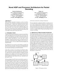
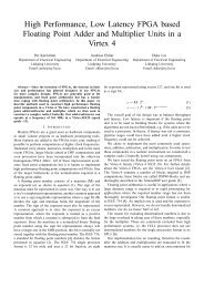
<strong>Implementation</strong> <strong>of</strong> A <strong>High</strong>-<strong>Speed</strong> <strong>Parallel</strong><br />
<strong>Turbo</strong> <strong>Decoder</strong> <strong>for</strong> <strong>3GPP</strong> LTE Terminals<br />
Di Wu, Rizwan Asghar, Yulin Huang and Dake Liu<br />
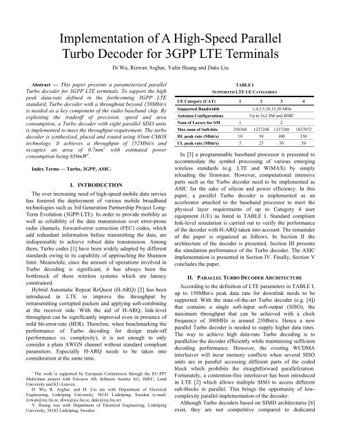
Abstract — This paper presents a parameterized parallel<br />
<strong>Turbo</strong> decoder <strong>for</strong> <strong>3GPP</strong> LTE terminals. To support the high<br />
peak data-rate defined in the <strong>for</strong>thcoming <strong>3GPP</strong> LTE<br />
standard, <strong>Turbo</strong> decoder with a throughout beyond 150Mbit/s<br />
is needed as a key component <strong>of</strong> the radio baseband chip. By<br />
exploiting the trade<strong>of</strong>f <strong>of</strong> precision, speed and area<br />
consumption, a <strong>Turbo</strong> decoder with eight parallel SISO units<br />
is implemented to meet the throughput requirement. The turbo<br />
decoder is synthesized, placed and routed using 65nm CMOS<br />
technology. It achieves a throughput <strong>of</strong> 152Mbit/s and<br />
occupies an area <strong>of</strong> 0.7mm 2 with estimated power<br />
consumption being 650mW 1 .<br />
Index Terms — <strong>Turbo</strong>, <strong>3GPP</strong>, ASIC.<br />
I. INTRODUCTION<br />
The ever increasing need <strong>of</strong> high-speed mobile data service<br />
has fostered the deployment <strong>of</strong> various mobile broadband<br />
technologies such as 3rd Generation Partnership Project Long-<br />
Term Evolution (<strong>3GPP</strong>-LTE). In order to provide mobility as<br />
well as reliability <strong>of</strong> the data transmission over error-prone<br />
radio channels, <strong>for</strong>ward-error correction (FEC) codes, which<br />
add redundant in<strong>for</strong>mation be<strong>for</strong>e transmitting the data, are<br />
indispensable to achieve robust data transmission. Among<br />
them, <strong>Turbo</strong> codes [1] have been widely adopted by different<br />
standards owing to its capability <strong>of</strong> approaching the Shannon<br />
limit. Meanwhile, since the amount <strong>of</strong> operations involved in<br />
<strong>Turbo</strong> decoding is significant, it has always been the<br />
bottleneck <strong>of</strong> these wireless systems which are latency<br />
constrained.<br />
Hybrid Automatic Repeat ReQuest (H-ARQ) [2] has been<br />
introduced in LTE to improve the throughput by<br />
retransmitting corrupted packets and applying s<strong>of</strong>t-combining<br />
at the receiver side. With the aid <strong>of</strong> H-ARQ, link-level<br />
throughput can be significantly improved even in presence <strong>of</strong><br />
mild bit-error-rate (BER). There<strong>for</strong>e, when benchmarking the<br />
per<strong>for</strong>mance <strong>of</strong> <strong>Turbo</strong> decoding <strong>for</strong> design trade-<strong>of</strong>f<br />
(per<strong>for</strong>mance vs. complexity), it is not enough to only<br />
consider a plain AWGN channel without standard compliant<br />
parameters. Especially H-ARQ needs to be taken into<br />
consideration at the same time.<br />
1 The work is supported by European Commission through the EU-FP7<br />
Multi-base project with Ericsson AB, Infineon Austria AG, IMEC, Lund<br />
University and KU-Leuven.<br />
D. Wu, R. Asghar, and D. Liu are with Department <strong>of</strong> Electrical<br />
Engineering, Linköping University, 58183 Linköping, Sweden (e-mail:<br />
rizwan@isy.liu.se, diwu@isy.liu.se, dake@isy.liu.se)<br />
Y. Huang was with Department <strong>of</strong> Electrical Engineering, Linköping<br />
University, 58183 Linköping, Sweden.<br />
TABLE I<br />
SUPPORTED LTE UE CATEGORIES<br />
UE Category (CAT) 1 2 3 4<br />
Supported Bandwidth<br />
1,4,3,5,10,15,20 MHz<br />
Antenna Configurations<br />
Up to 2x2 SM and SFBC<br />
Num <strong>of</strong> Layers <strong>for</strong> SM 1 2<br />
Max num <strong>of</strong> S<strong>of</strong>t-bits 250368 1237248 1237248 1827072<br />
DL peak rate (Mbit/s) 10 50 100 150<br />
UL peak rate (Mbit/s) 5 25 50 50<br />
In [3] a programmable baseband processor is presented to<br />
accommodate the symbol processing <strong>of</strong> various emerging<br />
wireless standards (e.g. LTE and WiMAX) by simply<br />
reloading the firmware. However, computational intensive<br />
parts such as the <strong>Turbo</strong> decoder need to be implemented as<br />
ASIC <strong>for</strong> the sake <strong>of</strong> silicon and power efficiency. In this<br />
paper, a parallel <strong>Turbo</strong> decoder is implemented as an<br />
accelerator attached to the baseband processor to meet the<br />
physical layer requirements <strong>of</strong> up to Category 4 user<br />
equipment (UE) as listed in TABLE I. Standard compliant<br />
link-level simulation is carried out to verify the per<strong>for</strong>mance<br />
<strong>of</strong> the decoder with H-ARQ taken into account. The remainder<br />
<strong>of</strong> the paper is organized as follows. In Section II the<br />
architecture <strong>of</strong> the decoder is presented. Section III presents<br />
the simulation per<strong>for</strong>mance <strong>of</strong> the <strong>Turbo</strong> decoder. The ASIC<br />
implementation is presented in Section IV. Finally, Section V<br />
concludes the paper.<br />
II. PARALLEL TURBO DECODER ARCHITECTURE<br />
According to the definition <strong>of</strong> LTE parameters in TABLE I,<br />
up to 150Mbit/s peak data rate <strong>for</strong> downlink needs to be<br />
supported. With the state-<strong>of</strong>-the-art <strong>Turbo</strong> decoder (e.g. [4])<br />
that contains a single s<strong>of</strong>t-input s<strong>of</strong>t-output (SISO), the<br />
maximum throughput that can be achieved with a clock<br />
frequency <strong>of</strong> 300MHz is around 25Mbit/s. Hence a new<br />
parallel <strong>Turbo</strong> decoder is needed to supply higher data rates.<br />
The way to achieve high data-rate <strong>Turbo</strong> decoding is to<br />
parallelize the decoder efficiently while maintaining sufficient<br />
decoding per<strong>for</strong>mance. However, the existing WCDMA<br />
interleaver will incur memory conflicts when several SISO<br />
units are in parallel accessing different parts <strong>of</strong> the coded<br />
block which prohibits the straight<strong>for</strong>ward parallelization.<br />
Fortunately, a contention-free interleaver has been introduced<br />
in LTE [2] which allows multiple SISO to access different<br />
sub-blocks in parallel. This brings the opportunity <strong>of</strong> lowcomplexity<br />
parallel implementation <strong>of</strong> the decoder.<br />
Although <strong>Turbo</strong> decoders based on SIMD architectures [6]<br />
exist, they are not competitive compared to dedicated
implementations. Furthermore, since the variation <strong>of</strong> <strong>Turbo</strong><br />
decoding procedure among different standards is small, a<br />
parameterized <strong>Turbo</strong> decoding accelerator is sufficient to<br />
achieve enough flexibility while maintaining area and power<br />
efficiency. In order to supply 150Mbit/s peak data rate<br />
required by LTE UE category 4, a parallel <strong>Turbo</strong> decoder with<br />
eight SISO units has been designed with its architecture<br />
depicted in Fig. 1.<br />
values at the beginning and end <strong>of</strong> sliding windows and<br />
parallel windows need to be saved which means the overhead<br />
is limited.<br />
A. SISO Unit<br />
SISO unit is the major block in a <strong>Turbo</strong> decoder. The input to<br />
s<br />
the SISO are: systematic a-prior in<strong>for</strong>mation λ a k , systematic<br />
intrinsic in<strong>for</strong>mation λ i s k and parity intrinsic in<strong>for</strong>mation λ i p<br />
k .<br />
In each SISO, classical sliding-window processing is applied<br />
to reduce the latency. In this paper, the size <strong>of</strong> the sliding<br />
window S sw is 64. Each SISO unit consists <strong>of</strong> α , β , γ and Log-<br />
Likelihood Ratio (LLR) units. Radix-2 log-Max decoding is<br />
used with the scaling <strong>of</strong> the extrinsic in<strong>for</strong>mation which<br />
allows a close log-MAP decoding per<strong>for</strong>mance to be<br />
achieved. The scaling factor ranges from 0.6 to 0.8.<br />
Fig. 1.<br />
Block Diagram <strong>of</strong> the <strong>Parallel</strong> <strong>Turbo</strong> <strong>Decoder</strong><br />
Fig. 3.<br />
Block Diagram <strong>of</strong> the SISO Unit<br />
Fig. 2.<br />
Scheduling Chart <strong>of</strong> a Half Iteration<br />
As defined in [2], the maximum code block size is 6144 in<br />
LTE which will incur very high latency when serial <strong>Turbo</strong><br />
decoder is used. A super windowing strategy [5] is adopted in<br />
this paper to speed up the decoding. First, the coded block will<br />
be partitioned into eight equally sized sub-blocks. Each SISO<br />
unit is responsible <strong>for</strong> the processing <strong>of</strong> one sub-block. The<br />
processing <strong>of</strong> one sub-block is considered as one parallel<br />
window with size S pw<br />
. Hence in total eight parallel windows<br />
can be processed in parallel, which reduced the processing<br />
time by eight times. The challenge when using parallel<br />
window is the absence <strong>of</strong> initial values at the border <strong>of</strong> each<br />
parallel window. As depicted in Fig. 1 and Fig. 3, a method<br />
namely Next Iteration Initialization (NII) [7] is used to<br />
estimate the initial values both sliding windows and parallel<br />
windows using the corresponding state metrics produced at<br />
previous iteration. This requires extra storage <strong>of</strong> α and β<br />
values. These values are saved in a first-in first-out (FIFO)<br />
between neighboring SISO units and the local buffer inside<br />
each SISO. There<strong>for</strong>e, the reduction <strong>of</strong> computational latency<br />
is at the cost <strong>of</strong> increased storage. Fortunately, only α and β<br />
• γ Unit: As depicted in Fig. 4(a), the γ units computes<br />
two transition metrics<br />
s s s s p<br />
γ10 = λak + λik , γ11<br />
= λak + λik + λik<br />
p<br />
(with γ 00 = 0 and γ 01 = λi k ) from the input.<br />
• α unit: α unit computes the <strong>for</strong>ward state metrics<br />
1<br />
( , ) , ( , )<br />
α m max<br />
b j m j b j m<br />
k = αk<br />
− 1<br />
γ k − 1<br />
j=<br />
0<br />
<strong>for</strong> each sub-block assigned to the SISO with size S pw<br />
. The<br />
result will be saved into a stack memory, from where, the β<br />
unit will read in a reversed order to compute the backward<br />
metrics. The α unit consists <strong>of</strong> mainly eight add-compareselect<br />
(ACS) units as depicted in Fig. 4(b).<br />
Fig. 4.<br />
γ and ACS Units<br />
• β unit: Similar to α unit, β unit also consists <strong>of</strong> eight<br />
ACS units. It computes the backward metrics<br />
1<br />
m j, m f ( j, m)<br />
k = max k k 1<br />
j=<br />
0<br />
β γ β +<br />
based on the result computed early by the γ unit. Here<br />
f ( jm , ) is the next state in the trellis when the input is j<br />
and current state being m. As NII method is used, the<br />
computed β values at the border <strong>of</strong> the sliding windows<br />
will be stored in a buffer to be used as initial value in the
jm f jm<br />
next iteration. Intermediate values γ , ( , )<br />
k β k + 1 which are<br />
computed half-way to get β m k will be passed directly to<br />
the LLR unit to compute the extrinsic in<strong>for</strong>mation Λ ( d k ).<br />
• LLR unit: It computes the extrinsic in<strong>for</strong>mation<br />
( m 1, m f (1, m ) 0, (0, )<br />
) ( m m f m )<br />
7 7<br />
Λ ( d ) = max α + γ + β − max α + γ + β<br />
Fig. 5.<br />
k k k k+ 1 k k k+<br />
1<br />
m= 0 m=<br />
0<br />
and the s<strong>of</strong>t-output based on the result from α unit and β<br />
unit. As the output <strong>of</strong> the SISO units, Λ ( d k ) is passed<br />
through the switch network to different memory banks <strong>for</strong><br />
later access by the SISO unit in the next iteration.<br />
0<br />
P1<br />
A1<br />
+<br />
–<br />
S1<br />
P2<br />
A2<br />
msb<br />
1<br />
0<br />
S2<br />
f2 >>1<br />
P3<br />
A3<br />
K<br />
AM<br />
+<br />
S3<br />
P4<br />
A4<br />
g(0)<br />
g_c<br />
1<br />
0<br />
R<br />
g_x_a<br />
S4<br />
P5<br />
<strong>Parallel</strong> Interleaver Architecture<br />
A5<br />
g_x_b<br />
g_x<br />
S5<br />
P6<br />
A6<br />
K<br />
AM<br />
+<br />
S6<br />
P7<br />
A7<br />
S<br />
R<br />
S7<br />
A<br />
P8<br />
A8<br />
achieved with the replication <strong>of</strong> the hardware <strong>for</strong> basic<br />
interleaver and getting support from a LUT providing the<br />
starting values. In this case a total <strong>of</strong> 32 additions are needed.<br />
However, <strong>for</strong> the sake <strong>of</strong> hardware reuse, part <strong>of</strong> the basic<br />
interleaver unit can be shared to generate multiple addresses at<br />
the same time. The optimized hardware uses 18 additions in<br />
total to generate 8 parallel interleaver addresses, thus saving<br />
14 additions. The hardware <strong>for</strong> parallel interleaver address<br />
generation <strong>for</strong> LTE is shown in Fig. 5.<br />
C. H-ARQ<br />
In LTE, two s<strong>of</strong>t-combining methods namely Chase<br />
Combining (CC) and Incremental Redundancy (IR) are<br />
supported. In this paper, only CC is considered. The base<br />
station retransmits the same packet when it receives the<br />
NACK signal from UE, and UE combines the LLR<br />
in<strong>for</strong>mation generated by the detector with those <strong>of</strong> the<br />
initially received packet. The gain <strong>of</strong> H-ARQ is at the cost <strong>of</strong><br />
larger s<strong>of</strong>t buffer used to store the demodulated s<strong>of</strong>t<br />
in<strong>for</strong>mation. In order to support the buffer size as large as<br />
1.8Mbits, high-density memory such as 1T-SRAM needs to be<br />
used. Since 1T-SRAM is different from the technology used<br />
<strong>for</strong> the decoder, it is not included in the results <strong>of</strong> this paper.<br />
B. <strong>Parallel</strong> Interleaver<br />
The internal interleaver involved with the <strong>Turbo</strong> Code in<br />
<strong>3GPP</strong>-LTE is based on quadratic permutation polynomial<br />
(QPP). Thanks to the QPP interleaver [2] which allows<br />
conflict-free parallel access, the implementation <strong>of</strong> the parallel<br />
interleaver is straight-<strong>for</strong>ward. In this paper, to support the<br />
parallel <strong>Turbo</strong> decoder, a configurable parallel interleaver is<br />
adopted. It can generate eight addresses in parallel <strong>for</strong> the data<br />
access <strong>of</strong> eight SISO units. QPP interleavers have very<br />
compact representation methodology and also inhibit a<br />
structure that allows the easy analysis <strong>for</strong> its properties. The<br />
interleaving function <strong>for</strong> turbo code is specified by the<br />
following quadratic permutation polynomial:<br />
2<br />
( )<br />
A( x) = f1ix+<br />
f2 i x % K<br />
(1)<br />
Here x = 0,1, 2, …( K − 1) , where K is the block size. This<br />
polynomial provides deterministic interleaver behavior <strong>for</strong><br />
different block sizes with appropriate values <strong>of</strong> f 1<br />
and f<br />
2<br />
.<br />
Direct implementation <strong>of</strong> the permutation polynomial given in<br />
eq. (1) is in-efficient due to multiplications, modulo function<br />
and bit growth problem. The simplified hardware solution is<br />
to use recursive approach adopted in [8] and [9]. Eq. (1) can<br />
be re-written <strong>for</strong> recursive computation as:<br />
( A )<br />
A( x+ 1) = ( x) + g( x) % K<br />
(2)<br />
Where g( x) = ( f1+ f2+ 2. f2. x)<br />
% K , which can also be<br />
computed recursively as g( x+ 1)<br />
= ( g( x) + 2. f2)<br />
% K . The two<br />
recursive terms I ( x+<br />
1)<br />
and g<br />
( x + 1)<br />
are easy to compute and they<br />
provide the basic interleaver functionality <strong>for</strong> LTE.<br />
Owing to the parallelism inherited in the QPP interleaver,<br />
the generation <strong>of</strong> parallel interleaver addresses can be<br />
Fig. 6.<br />
Fig. 7.<br />
BER<br />
10 −2<br />
10 −3<br />
10 −4<br />
10 −5<br />
10 −6<br />
uncoded BER<br />
coded BER <strong>Parallel</strong> <strong>Turbo</strong><br />
coded BER Serial <strong>Turbo</strong><br />
10 −7<br />
20 22 24 26 28 30 32<br />
10 −1 SNR [dB]<br />
Bit-Error-Rate (rate 0.926, 64-QAM)<br />
throughput [Mbit/s]<br />
40<br />
35<br />
30<br />
25<br />
20<br />
15<br />
10<br />
5<br />
coded throughput Serial <strong>Turbo</strong><br />
coded throughput <strong>Parallel</strong> <strong>Turbo</strong><br />
uncoded throughput<br />
0<br />
20 22 24 26 28 30 32<br />
SNR [dB]<br />
Link-level Throughput (rate 0.926, 64-QAM)<br />
III. SIMULATION AND SYSTEM PERFORMANCE<br />
In order to benchmark the parallel <strong>Turbo</strong> decoder,<br />
simulation is carried out based on a <strong>3GPP</strong> LTE link-level
simulator. The simulator is compatible to <strong>3GPP</strong> specification<br />
defined in 36.211 and 36.212 [2]. The <strong>3GPP</strong> SCME model<br />
[10] is used as the channel model. In the simulation, 5000<br />
subframes have been simulated. 64-QAM modulation and 5/6<br />
coding rate is used. S<strong>of</strong>t-output sphere decoder which<br />
achieves ML per<strong>for</strong>mance is used as the detection method. No<br />
close-loop precoding is assumed. At most three<br />
retransmissions are allowed in the CC based H-ARQ.<br />
Simulation results are depicted in Fig. 6 and Fig. 7. Note that<br />
in the simulation, only 5MHz band is used instead <strong>of</strong> 20MHz<br />
band <strong>for</strong> the maximum throughput. The link-level BER and<br />
throughput figures show that the per<strong>for</strong>mance degradation<br />
introduced by the approximations (e.g. the NII based<br />
approximation) adopted in the parallel decoder is very small.<br />
TABLE II<br />
COMPARISON OF ASIC IMPLEMENTATION RESULTS<br />
<strong>Turbo</strong> <strong>Decoder</strong> This Work [4]<br />
Technology CMOS 65nm CMOS 130nm<br />
Supply Voltage 1.2V 1.2V<br />
Logic Size 70kgate 44.1kgate<br />
Total Memory 250kb 120kb<br />
Total Area 0.7mm 2 1.2mm 2<br />
Working Frequency 250MHz 246MHz<br />
Throughput 152Mbps 10.8Mbps<br />
Estimated Power 650mW 32.4mW<br />
Silicon Area/Throughput 0.005 mm 2 /Mbps 0.11 mm 2 /Mbps<br />
Power Efficiency 0.71nJ/b/iter 0.54nJ/b/iter<br />
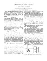
IV. ASIC IMPLEMENTATION<br />
The <strong>Turbo</strong> decoder is implemented using 65nm CMOS<br />
process from STMicroelectronics. After placement and<br />
routing, it easily runs at 250MHz with a core area <strong>of</strong> 0.7mm 2 .<br />
The throughput <strong>of</strong> the Radix-2 parallel decoder can be<br />
computed as:<br />
Sblk,max<br />
× fclk<br />
T =<br />
(3)<br />
S + S + C × × N<br />
( )<br />
pw,max sw extra 2 ite<br />
Sblk<br />
,max<br />
Nsiso<br />
blk<br />
where S pw,max<br />
= . Here S<br />
,max<br />
= 6144 is the maximum<br />
number <strong>of</strong> bits per codeword defined in [2], N siso = 8 is the<br />
number <strong>of</strong> SISO units, S sw = 64 is the sliding window size,<br />
C extra = 10 is the number <strong>of</strong> overhead cycles, fclk<br />
= 250MHz<br />
is<br />
the clock frequency and N ite is the number <strong>of</strong> decoding<br />
iterations. The throughput <strong>of</strong> the decoder is 152Mbit/s in case<br />
N ite = 6 . In high SNR region, early stopping can effectively<br />
reduce the number <strong>of</strong> iterations needed to four. This gives a<br />
throughput <strong>of</strong> 228Mbit/s. Theoretically, <strong>for</strong> 20MHz<br />
bandwidth with 2× 2 Spatial Multiplexing and 64-QAM, the<br />
required throughput <strong>of</strong> <strong>Turbo</strong> decoding is 176Mbit/s, which<br />
means the presented implementation is sufficient <strong>for</strong> CAT4<br />
PDSCH decoding. Owing to the scalability <strong>of</strong> the on-chip<br />
network in [3], the <strong>Turbo</strong> decoder can be easily wrapped and<br />
integrated with the programmable plat<strong>for</strong>m. TABLE II depicts<br />
the ASIC implementation result in comparison to the prior-art<br />
presented in [4]. The result shows that work in this paper<br />
achieves more than 10 times data throughput compared to [4]<br />
while achieving higher silicon efficiency and slightly lower<br />
power efficiency even without the voltage scaling used in [4].<br />
V. CONCLUSION<br />
In this paper, a 650mW <strong>Turbo</strong> decoder is presented <strong>for</strong><br />
CAT4 LTE terminals. The design is based on<br />
algorithm/architecture co-optimization targeting a good trade<strong>of</strong>f<br />
between per<strong>for</strong>mance and throughput. The result shows<br />
that at feasible silicon cost, the parallel architecture<br />
significantly reduces the decoding latency while allowing a<br />
link-level per<strong>for</strong>mance that is close to the traditional serial<br />
decoder to be achieved.<br />
Fig. 8.<br />
S8<br />
Interleaver<br />
S7<br />
S2<br />
S1<br />
Control<br />
Layout <strong>of</strong> the <strong>Turbo</strong> <strong>Decoder</strong><br />
S6<br />
S3<br />
VI. ACKNOWLEDGMENT<br />
The authors would like to thank Christian Mehlführer and<br />
the Christian Doppler Laboratory <strong>for</strong> Design Methodology <strong>of</strong><br />
Signal Processing Algorithms at Vienna University <strong>of</strong><br />
Technology, <strong>for</strong> contributions on the simulators.<br />
REFERENCES<br />
[1] C. Berrou, A. Glavieux, and P. Thitimajshima, “Near Shannon limit<br />
error-correcting coding and decoding: <strong>Turbo</strong> Codes,” in Proc. IEEE<br />
ICC, 1993, pp. 1064-1070.<br />
[2] <strong>3GPP</strong>, “Tech. Spec. 36.212 V8.4.0, E-UTRA; Multiplexing and Channel<br />
Coding,” Sept 2008.<br />
[3] Nilsson, E. Tell, and D. Liu, “An 11 mm 2 70 mW Fully-Programmable<br />
Baseband Processor <strong>for</strong> Mobile WiMAX and DVB-T/H in 0.12µm<br />
CMOS,” in IEEE Journal <strong>of</strong> Solid-State Circuits, vol. 44, no. 1, pp. 90-<br />
97, 2009.<br />
[4] Benkeser, A. Burg, T. Cupaiuolo, Q. Huang, “Design and Optimization<br />
<strong>of</strong> an HSDPA <strong>Turbo</strong> <strong>Decoder</strong> ASIC,” in IEEE Journal <strong>of</strong> Solid-State<br />
Circuits, vol. 44, no. 1, pp. 98-106, 2009.<br />
[5] S.Yoon, and Y. Bar-Ness, “A <strong>Parallel</strong> MAP Algorithm <strong>for</strong> Low Latency<br />
<strong>Turbo</strong> Decoding,” in IEEE Communication Letters, vol 6, pp. 288-290,<br />
July, 2002.<br />
[6] M.C. Shin and I.C. Park. “SIMD processor-based <strong>Turbo</strong> decoder<br />
supporting multiple third-generation wireless standards,” in IEEE Trans.<br />
on VLSI, vol.15, pp. 801-810, June 2007.<br />
[7] A.Dingninou, F. Raouafi, and C. Berrou, “Organisation de la memoire<br />
dans un turbo decodeur utilisant l'algorithm SUB-MAP,” in Proceedings<br />
<strong>of</strong> Gretsi, pp. 71-74, Sept. 1999.<br />
[8] R. Asghar, D. Liu, “Dual standard re-configurable hardware interleaver<br />
<strong>for</strong> turbo decoding,” in Proceedings <strong>of</strong> IEEE ISWPC, May 2008, pp. 768<br />
- 772.<br />
[9] R. Asghar, D. Wu, J. Eilert and D. Liu, “Memory Conflict Analysis and<br />
<strong>Implementation</strong> <strong>of</strong> a Re-configurable Interleaver Architecture<br />
Supporting Unified <strong>Parallel</strong> <strong>Turbo</strong> Decoding,” in Journal <strong>of</strong> Signal<br />
Processing Systems; DOI: 10.1007/s11265-009-0394-8. To Appear.<br />
[10] D. S. Baum, J. Salo, M. Milojevic, P. Kyöti, and J. Hansen “MATLAB<br />
implementation <strong>of</strong> the interim channel model <strong>for</strong> beyond-3G systems<br />
(SCME),” May 2005.<br />
S5<br />
S4