High Performance, Low Latency FPGA based Floating Point Adder ...
High Performance, Low Latency FPGA based Floating Point Adder ...
High Performance, Low Latency FPGA based Floating Point Adder ...
- No tags were found...

Create successful ePaper yourself
Turn your PDF publications into a flip-book with our unique Google optimized e-Paper software.
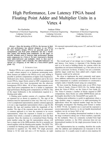
<strong>High</strong> <strong>Performance</strong>, <strong>Low</strong> <strong>Latency</strong> <strong>FPGA</strong> <strong>based</strong><strong>Floating</strong> <strong>Point</strong> <strong>Adder</strong> and Multiplier Units in aVirtex 4Per KarlströmDepartment of Electrical EngineeringLinkping UniversityEmail: perk@isy.liu.seAndreas EhliarDepartment of Electrical EngineeringLinkping UniversityEmail: ehliar@isy.liu.seDake LiuDepartment of Electrical EngineeringLinkping UniversityEmail: dake@isy.liu.seAbstract— Since the invention of <strong>FPGA</strong>s, the increase in theirsize and performance has allowed designers to use <strong>FPGA</strong>sfor more complex designs. <strong>FPGA</strong>s are generally good at bitmanipulations and fixed point arithmetics but has a hardertime coping with floating point arithmetics. In this paper wedescribe methods used to construct high performance floatingpoint components in a Virtex-4. We have constructed a floatingpoint adder/subtracter and multiplier which we then used toconstruct a complex radix-2 butterfly. Our adder/subtracter canoperate at a frequency of 361 MHz in a Virtex-4SX35 (speedgrade -12).I. INTRODUCTIONModern <strong>FPGA</strong>s are a great asset as hardware componentsin small volume projects or as hardware prototyping tools.More features are added to the <strong>FPGA</strong>s every year, making itpossible to perform computations at higher clock frequencies.Dedicated carry chains, memories, multipliers and in the mostrecent <strong>FPGA</strong>s, larger blocks aimed at DSP computations andeven processors have been incorporated into the otherwisehomogenous <strong>FPGA</strong> fabric. All of these improvements acceleratefixed point computations but it is harder to implementhigh performance floating point computations on <strong>FPGA</strong>s. Oneof the major bottlenecks is the normalization required in afloating point adder.A floating point number consists of a mantissa (M) andan exponent (e) as shown in equation (1). The sign of themantissa must be represented in some way. One way is to usea two’s-complement representation, another common approachis to use a sign magnitude representation where a sign bit (S)decides the sign and mantissa holds the magnitude of thenumber. The sign of the exponent must also be represented.A common approach is to store the exponent in an excessrepresentation, where the exponent is treated as a positivenumber from which a constant is subtracted to form the finalexponent. Since the mantissa in a normalized binary floatingpoint number using the sign bit representation always willhave a single one in the MSB position, this bit is normally notstored together with the floating point number. The IEEE 754,a standard for floating point numbers [4], dictates the formatpresented in equation (2). The IEEE 754 single precisionformat is 32 bit wide and uses a 23 bit fraction, an eightbit exponent represented using excess 127, and one bit is usedas a sign bit.x = M · 2 e (1)x = (−1) S · 1.M · 2 e−excess (2)The overall goal of our design was to balance throughputand latency. <strong>Low</strong> latency is important if the floating pointunit is to be used as building blocks for systems where thealgorithms are not known beforehand, e.g. if the units are to beused in a processor. In theory, if latency was not a constraint,pipeline stages could have been added until a higher clockfrequency could not be achieved.We chose to implement the most commonly used operations,addition, subtraction, and multiplication. In order to testthese components in a realistic environment we constructed acomplex radix-2 butterfly kernel using our components.We have tested the floating point units on an <strong>FPGA</strong> fromthe Virtex-4 family (Virtex-4 SX35-10). For further detailsabout the Virtex-4 <strong>FPGA</strong>, see the Virtex-4 User Guide [2].The Virtex-4 contains a number of blocks targeted at DSPcomputations, these blocks are called DSP48-blocks and arethoroughly described in the XtremeDSP user guide [3].<strong>Floating</strong> point arithmetics is useful in applications where alarge dynamic range is required or in rapid prototyping forapplications where the required number range has not beenthoroughly investigated. Our floating point format is similarto IEEE 754 [4]. An implicit one is used and the exponent isexcess-represented. However, we do not handle denormalizednumbers, nor do we honor NaN or Inf.The reason for excluding denormalized numbers is due tothe large overhead in taking care of these numbers, especiallyfor the multiplier. These are commonly excluded from highperformance systems, i.e. the CELL processor does not usedenormalized numbers for the single precession format in itsSPUs [6].Our implementation has no rounding, therefore the resultsafter the addition and multiplication are truncated to fit themantissa size. It is usually easier to add en extra mantissa bit
to handle the same precision as achieved when using moreelaborate rounding schemes.II. RELATED WORKA number of attempts at constructing floating point arithmeticsin <strong>FPGA</strong>s have been done and presented in theacademia. Although many of the papers are a bit old and fewtarget modern <strong>FPGA</strong>s such as the Virtex-4.<strong>High</strong>-performance floating point arithmetics on <strong>FPGA</strong> isdiscussed in [5] Although the paper has some interestingfigures about the area versus pipeline depth tradeoff, theirdesign seems to be a bit to general to utilize the full potentialof the <strong>FPGA</strong>. I.e. to reach 250 MHz for the adder they haveto use 19 pipeline stages on a Virtex2Pro speed grade -7.To be fully IEEE 754 compliant the FPU needs to, inone way or another, support denormalized numbers, be iteither with interrupts, letting the processor deal with theseuncommon numbers or having direct support for denormalsin hardware. For a good discussion on different strategiesto handle denormals see [7]. Although it is a good generaldiscussion the paper does not cover any <strong>FPGA</strong> specific details.An interesting approach to tailor floating point computationsto <strong>FPGA</strong>s are to use higher than 2-radix floating points sincethis maps better to the <strong>FPGA</strong> fabric. This is better describedin [11].Full IEEE 754 rounding requires the FPU to support, roundto nearest even, round to minus infinity, round to positiveinfinity, and round to zero. A more detailed discussion aboutrounding is presented in [8]. This paper does not deal withany <strong>FPGA</strong> specific implementations.Since the invention of <strong>FPGA</strong>s and their increase in performance,IP cores for <strong>FPGA</strong>s has started to appear in themarket. Both Nallatech [9] and Xilinx [10] has IP cores fordouble and single precision floating point format. Neither ofthese companies publish low level techniques used in their IPcores.III. METHODOLOGYAs a reference for the RTL code we implemented a C++library for floating point numbers. The number of bits in themantissa and exponents could be configured from 1 to 30 bits.The C++ model was later used to generate the test vectors forthe RTL test benches. Using a mantissa width of 23 and anexponent width of 8 the C++ model was tested against thefloating point implementation used in the development PC.The only differences occurred due to the different roundingmodes.Initial RTL code was written using Verilog adhering tothe C++ model. The performance of the initial RTL modelwas evaluated and the most critical parts of the design wereoptimized to better fit the <strong>FPGA</strong>. This was repeated until theperformance was satisfactory and no bugs were discovered bythe test benches.IV. IMPLEMENTATIONThe implementation was written in Verilog and ISE 8.2i wasused to synthesize, place, and route the design.A. MultiplierA floating point multiplier is conceptually easy to construct.The new mantissa is formed as a multiplication of the oldmantissas. In order to construct a good multiplier some <strong>FPGA</strong>specific optimizations were needed. The 24×24 bit multiplicationof the mantissa is constructed using four of the Virtex-4’sDSP48 blocks to form a 35×35 bit multiplier with a latencyof five clock cycles. For a thorough explanation of how toconstruct such a multiplier the reader is referred to [3]. Thenew exponent is even easier to construct, a simple additionwill suffice. The new sign is computed as an exclusive-or ofthe two original signs. The result of the multiplication hasto be normalized, this is a simple operation since the mostsignificant bit of the mantissa can only be located at one outof two bit positions given normalized inputs to the multiplier.The exponent is adjusted accordingly in an additional adder.B. <strong>Adder</strong>/SubtracterA floating point adder/subtracter is more complicated than afloating point multiplier. The basic adder architecture is shownin Figure 1. The first step compares the operands and swapsthem if necessary so that the smallest number enters the pathwith the alignment shifter. If the input operands are non-zero,the implicit one is also added in this first step. In the next step,the smallest number is shifted down by the exponent differenceso that the exponents of both operands match. After this step,an addition or subtraction of the two numbers are performed.A subtraction can never cause a negative result because of theearlier comparison and swap step.The normalization step is the final and most complicatedstep. It is implemented using three pipeline stages. Figure 2depicts the architecture of the normalizer. The following isdone in each pipeline stage:1) The mantissa is processed in parallel in a number ofmodules, each looking at four bits of the mantissa. Thefirst module operates on the first four bits and outputsa normalized result assuming a one was found in thesebits. An extra output signal, shown as dotted lines inFigure 2, is used to signal if all four bits were zero.The second module assumes that the first four bitswere all zero and instead operates on the next fourbits, outputting a normalized result. This is repeated forthe remaining bits of the mantissa. Each module alsogenerates a value needed to correct the exponent, this ismarked as dotted lines in Figure 2.2) One of the previous results, both mantissa and exponentoffset value, is selected to be the final output. If all bitswere zero, a zero is generated as the final result.3) The mantissa is simply delayed to synchronize withthe exponent. The exponent is corrected with the offsetselected in the previous stage.Our normalization uses a rather hardware expensive approacha less hardware expensive architecture could be used ifdeeper pipelines were allowed. The modules in the first stageof the normalizer looks at four bits each, the choice to look at
XC4VSX-12 XC2VP-7 XC2V-6 XC3SE-5 XC3S-5Freq. 361 MHz 288 MHz 250 MHz 202 MHz 174 MHzTABLE IIIFAMILY COMPARISONTable IV list the resource utilization of the steps in Figure 1.To avoid the extra delays associated with the <strong>FPGA</strong> I/O pinstwo extra pipeline stages before and and one stage after wereinserted into the top module. These extra flip flops are notincluded in the resource utilization metrics.Table V compares our results from the adders (DA) againstsome other results published, although we do not handledenormalized numbers or all rounding modes in our design weare confident that no more than three pipeline stages needs tobe added to make the units fully IEEE 754 complaint. USC [5]does not consider NaN or denormals and Nallatech [9] usesan alternative internal floating point format and can thus alsoavoid handling denormals. Thus the comparisons here are notcompletely fair they still give a good picture of how theperformance of our floating point units compare to other <strong>FPGA</strong>implementations.23 bit M, 8 bit e 15 bit M, 10 bit eLUT FF LUT FFCompare/Select 113 149 99 129Align 97 57 100 44Add 31 33 26 33Normalization 326 222 225 145Total 567 461 450 351TABLE IVADDER RESOURCE UTILIZATIONXC2VP-6XC2VP-7DA Nallatech Xilinx DA USC<strong>Adder</strong>Speed 248 MHz 184 MHz 269 MHz 288 MHz 250 MHz<strong>Latency</strong> 7 14 11 7 19TABLE VCOMPARISON WITH OTHER IMPLEMENTATIONSVI. DISCUSSIONThere are a number of opportunities for further optimizationsin this design. For example, instead of using CLBs forthe shifting, a multiplier could be used for this task by sendingin the number to be shifted as one operand and a bit vectorwith a single one in a suitable position as the other operand.If the application of the floating point blocks are knownit is possible to do some application specific optimizations.For example, in a butterfly with an adder and a subtracter,operating on the same operands, the first compare stage couldbe shared between these. If the application can tolerate it,further pipelining could increase the performance significantly.If the latency tolerance is very high, bit serial arithmetics couldprobably be used as well. In this project we limited the pipelinedepth to compare well with FPUs used in CPUs.According to a post on comp.arch.fpga it is possibleto achieve 400MHz performance in a XC4VSX55-10 forIEEE 754 single precision floating point arithmetics [1]. Fewdetails are available but a key technique is to use the DSP48block for the adder since an adder implemented with a carrychain would be too slow. The post normalization step issupposed to be implemented using both DSP48 and BlockRAMs. The pipeline depth of this implementation is notknown, although what is known is that the normalizationconsists of 11 pipeline stages.It would also be interesting to look at the newly announcedVirtex-5 <strong>FPGA</strong>. The 6-LUT architecture should reduce thenumber of logic levels and routing all over the design. As anexample, one could investigate if the parallel shifting modulesin the normalizer should take six bits as input since it couldmap well to the six input LUT architecture of the Virtex-5 orif the fact that a 4-to-1 mux can be constructed in a six inputLUT still favors the current four bits per module architecture.A final step of this research would be to implement allrounding modes and at least generate flags so a software solutioncan deal with denormals and the other special numbersdefined in IEEE 754.VII. CONCLUSIONWe have shown that it is possible to achieve good floatingpoint performance with low latency in modern <strong>FPGA</strong>s. Tomake maximal use of an <strong>FPGA</strong> it is important to takeinto account the specific architecture of the targeted <strong>FPGA</strong>.The most important optimization we did was to perform thenormalization in a parallel fashion.The parallel normalization approach proved to be efficientsince it reduced the number of pipeline stages needed toperform the normalization operation.REFERENCES[1] Andraka, Ray; Re: <strong>Floating</strong> point reality check, news:comp.arch.fpga, 14May 2006[2] Xilinx; Virtex-4 User Guide[3] Xilinx; XtremeDSP for Virtex-4 <strong>FPGA</strong>s User Guide[4] ANSI/IEEE Std 754-1985 IEEE Standard for Binary <strong>Floating</strong>-<strong>Point</strong> Arithmetic[5] Govindu G., Zhuo L., Choi S, and Prasanna V. Analysis of <strong>High</strong>performance<strong>Floating</strong>-point Arithmetic on <strong>FPGA</strong>s[6] Oh H., Mueller S. M. Jacobi C. et al A Fully Pipelined Single-Precision<strong>Floating</strong>-<strong>Point</strong> Unit in the Synergistic Processor Element of a CELLProcessor[7] Schwarz M. E., Schmookler M., and Trog S. Hardware Implementationsof Denormalized Numbers[8] Santoro M. R., Bewick G., and Horowitz M. A. Rounding Algorithms forIEEE Multipliers[9] Nallatech http://www.nallatech.com[10] Xilinx <strong>Floating</strong>-point Operator v2.0http://www.xilinx.com/bvdocs/ipcenter/data sheet/floating point ds335.pdf[11] Cantanzaro R. and Nelson B. <strong>High</strong>er Radix <strong>Floating</strong>-<strong>Point</strong> Representationfor <strong>FPGA</strong>-Based Arithmetic