Measurement and assembly manual - Isotra
Measurement and assembly manual - Isotra
Measurement and assembly manual - Isotra

Create successful ePaper yourself
Turn your PDF publications into a flip-book with our unique Google optimized e-Paper software.
MEASUREMENT AND ASSEMBLY MANUAL<br />
NEOISOLITE<br />
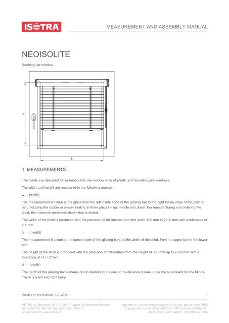
Rectangular window<br />
1. MEASUREMENTS<br />
The blinds are designed for <strong>assembly</strong> into the window wing of plastic <strong>and</strong> wooden Euro windows.<br />
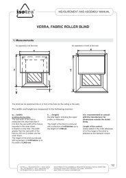
The width <strong>and</strong> height are measured in the following manner:<br />
w.... (width)<br />
The measurement is taken at the glass from the left inside edge of the glazing bar to the right inside edge of the glazing<br />
bar, including the rubber or silicon sealing in three places – up, middle <strong>and</strong> down. For manufacturing <strong>and</strong> ordering the<br />
blind, the minimum measured dimension is stated.<br />
The width of the blind is produced with the precision of millimetres from the width 400 mm to 2000 mm with a tolerance of<br />
± 1 mm.<br />
h .... (height)<br />
The measurement is taken at the same depth of the glazing bars as the width of the blind, from the upper bar to the lower<br />
bar.<br />
The height of the blind is produced with the precision of millimetres from the height of 300 mm up to 2200 mm with a<br />
tolerance of -3 / +27mm.<br />
d .... (depth)<br />
The depth of the glazing bar is measured in relation to the use of the distance bases under the side board for the blinds.<br />
There is a left <strong>and</strong> right base.<br />
Validity of the <strong>manual</strong>: 1. 9. 2014 1
MEASUREMENT AND ASSEMBLY MANUAL<br />
Depth of the glazing bar:<br />
19 <strong>and</strong> more mm - no base<br />
15 - 19 mm one base<br />
on each side<br />
11 - 15 mm two bases on each side<br />
Maximum guaranteed area: 2.5 m 2<br />
Dimensions outside the stated limits are recommended to be consulted with the manufacturer.<br />
The ideal measurements of the blind are in the diagram. Such measurements can be taken by using the cut of the upper<br />
profile, the side board; by placing this aid on the glazing bar, it is possible to measure the point, maximum possible width of<br />
the blind <strong>and</strong> from this point the dimension of the same point on the opposite side is measured. This marking is always<br />
influenced by the form <strong>and</strong> size of the glazing bar of the window profile.<br />
2. ASSEMBLY<br />
Assemble exactlty according to this <strong>manual</strong> to prevent redundant <strong>assembly</strong> errors <strong>and</strong> other related problems.<br />
AIDS FOR ASSEMBLY:<br />
<br />
<br />
<br />
electric drill, drills<br />
cross-head screwdriver<br />
knife, scissors, pliers<br />
for fixing blinds<br />
for fixing the holder of the<br />
chain<br />
hole for tightening pin<br />
screw 3 x 17; 3 x 25; 3 x 35 3,9 x 16 3.2 mm for plastic windows<br />
drill with the diameter Ø 2 mm 2,5 mm<br />
<strong>and</strong> Al windows; 3 mm for<br />
wooden windows<br />
INSPECTION:<br />
<br />
Before <strong>assembly</strong> we recommend inspecting all the parts after the delivery of the goods to prevent any problems. The<br />
manufacturer must be notified of any defects or comments concerning the <strong>assembly</strong> or blinds.<br />
ASSEMBLY<br />
<br />
<br />
never exp<strong>and</strong> the blind before <strong>assembly</strong><br />
on the blind in the window wing check that the dimension corresponds to the width of the window<br />
Validity of the <strong>manual</strong>: 1. 9. 2014 2
MEASUREMENT AND ASSEMBLY MANUAL<br />
<br />
<br />
<br />
<br />
<br />
<br />
<br />
<br />
<br />
<br />
<br />
<br />
<br />
check that the control mechanism is located on the correct side; it is possible to relocate the control mechanism, if<br />
necessary, although only after prior training<br />
depending on the depth <strong>and</strong> form of the glazing bar, support the blind using pads<br />
turn the rolled blind <strong>and</strong> remove the part for fixation of the corner clamp if this part is not in the displayed place which is<br />
inserted into the hole in the board<br />
insert the part into the corner clamp <strong>and</strong> screw the whole set into the glazing bar delivered with the screw, 3 mm<br />
diameter so one can freely move the corner clamp in the direction of the centre of the window<br />
insert the whole blind into the prepared <strong>and</strong> clamped corner clamps <strong>and</strong> mark the position of the corner clamps<br />
remove the blind <strong>and</strong> screw the corner clamps into the glazing bars with the delivered screws into the suitable prepressed<br />
holes<br />
for plastic windows, always screw into the glazing bars<br />
again insert the whole blind into the fixed corner clamps<br />
at the end, press the side covers into the holes in the corner clamps up to the stop.<br />
drill holes for the tightening pins of the leading nylons upwards into the lower part of the glazing bar<br />
ascertain by drawing at both ends of the nylon, the possibility of movement of the spring in the grid <strong>and</strong> find the<br />
approximate centre. Tie a knot on the nylon on one side; at the level of the glazing bar, shorten the nylon after the knot<br />
to about 10 mm <strong>and</strong> insert it into the drilled hole <strong>and</strong> push the first pin. On the other side tie a knot about 50 mm above<br />
the level of the glazing bar, tighten the nylon using pliers (do not damage the nylon by cutting with the pliers which<br />
would cause scratching of lamellas) <strong>and</strong> insert the knot into the hole.<br />
fix the clamping piece of the chain; for plastic windows again only secure into the glazing bar,<br />
check the function of the blind<br />
If the shape or the size of the glazing bar does not enable drilling holes for the tightening pins into the glazing bar from<br />
upwards, choose the option of drilling the holes for pins into the face of the glazing bar. With this option take care not to<br />
damage the glass with the drill. It is important to state the correct depth of the drilling! The client must be informed in<br />
advance of this form of <strong>assembly</strong> <strong>and</strong> consent in writing in the h<strong>and</strong>ing over protocol. Finally, ensure the full functionality of<br />
the blind <strong>and</strong> the window.<br />
ATTENTION!<br />
During <strong>assembly</strong> it is necessary to place the blind in the window when it is lifted up; mark the position of the screws on the<br />
window wing, fit the blind <strong>and</strong> then lower it. Each manipulation of the blind before <strong>assembly</strong> (if necessary) is only to be<br />
in the horizontal position! Any other manipulation is forbidden <strong>and</strong> claims for such damaged blinds will not be accepted!<br />
NOTE: for fixed windows a minimum gap of 45 mm is necessary between the reveal <strong>and</strong> the cover bar (in the case of<br />
smaller dimension, it is not possible to insert the side cover into the upper profile).<br />
Validity of the <strong>manual</strong>: 1. 9. 2014 3
MEASUREMENT AND ASSEMBLY MANUAL<br />
ATTENTION!<br />
Pursuant to the EN 13120:2014 st<strong>and</strong>ard, window blinds shall be installed in accordance with the<br />
following instructions:<br />
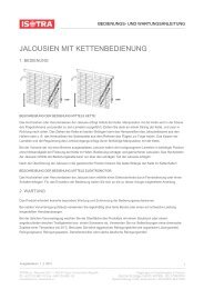
Chain:<br />
If a breakaway coupler is used:<br />
The chain length must be limited as follows:<br />
1) If installation height (H0) is not specified, the chain length (H2) shall be less than or equal to 2/3 of the blind height<br />
(see Fig. 1): H2 ≤ 2/3 H.<br />
2) If installation height (H0) is specified, the distance from the floor to the bottom part of the pull cord (H1) shall be at<br />
least 0.6 m: H1 > 0.6 m.<br />
A dangerous loop must be eliminated when a mass of 6 kg is applied or within 5 seconds of application.<br />
APPLY ONE HALF OF THE COUPLER TO EACH END OF THE CHAIN AND THEN LOCK BOTH COUPLER HALVES.<br />
Validity of the <strong>manual</strong>: 1. 9. 2014 4
MEASUREMENT AND ASSEMBLY MANUAL<br />
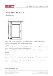
ILLUSTRATIVE ASSEMBLY<br />
Validity of the <strong>manual</strong>: 1. 9. 2014 5