JAPANESE PANEL BLINDS - Isotra
JAPANESE PANEL BLINDS - Isotra
JAPANESE PANEL BLINDS - Isotra

You also want an ePaper? Increase the reach of your titles
YUMPU automatically turns print PDFs into web optimized ePapers that Google loves.
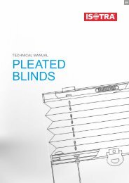
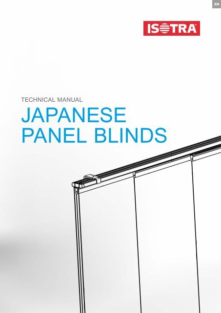
TECHNICAL MANUAL<strong>JAPANESE</strong><strong>PANEL</strong> <strong>BLINDS</strong>EN
Table of Contents – Japanese Panel BlindsBasic Product Specification 4Motor Control 5 - 6Measuring Instructions 7Installation Instructions 7 - 8Configurations 9Safety features according to the standards EN 13120+A1; EN 16 433; EN 16 434 10A brand symbolizing years of tradition, innumerable investments into research and development,use of high-quality materials, technological advancement, reliable work of hundreds of employeesand many more parameters, which together form one whole - the final product of the company ISOTRA.2
<strong>JAPANESE</strong> <strong>PANEL</strong> <strong>BLINDS</strong>Japanese Panel Blinds▲ original design for complex shading regardless of numberof windows or wings▲ alternative to blinds and roller blinds▲ rails made of extruded aluminum in white or silver color▲ wide range of fabrics of various decors and materials▲ electrical control option3
Japanese Panel BlindsBasic Product SpecificationCord control / Wand controlWall bracketClutch linesCelling bracketRailAdjustablestop travelBuggySpacing stopperEnd cap of cord typEnd mechanismControl loopSpacing stopperRunning profile PVCCounter magnetCordRight end capHanging profile of panelControl wandHedge furbelowsCord weightFabricLeft end capHedge furbelows2-00585-XXXX-BPanel weightRight end capManual ControlFor pulling the fabric panels to the side, to the center or from the center (based on control method):Cord – cord length = 2/3 of the Japanese panel blind height. White and silver color.Wand – wand length: 1170 mm. White and silver color.Motor ControlABC-04-LW motor (power of 7 W, power supply of 12-24V DC – 0.6 A). A 2-channel carrying bracket cannot be used with motor control.Technical DetailsTypeMaterialColor2 channels3 channels4 channels5 channelsRAL 9016 WhiteRAL 7036 SilverHead Rail Atypical Designs InstallationAlnoin window aperture (ceiling)before window aperture (wall)Standard Dimensions Minimum Width (mm) Maximum Width (mm) Minimum Height (mm) Maximum Height (mm)1000 5800 1000 3200Note: In the case of the height exceeding 2700 mm, the fabric choice must be consulted with the manufacturer.The maximum size of the individual panels is given by the dimensional limit of the individual fabrics.Determination of the individual panel width depends on the carrying bracket type, resp. on the number of required panels and total width of the accessory.4
<strong>JAPANESE</strong> <strong>PANEL</strong> <strong>BLINDS</strong>Japanese Panel BlindsMotor ControlInput 12-24V DC / 0,6 AController connectorsAerialProgram button3-channel carrying bracket4-channel carrying bracket5-channel carrying bracketABC-04-LW Technical ParametersSupply voltage12-24V DC / 0,6 APower input7WBall-chain speed3,75 m/min.Maximum pulling power3 KgOperating temperature 5°- 60°CMaximum number of coupled channels 32Auxiliary setupReverse move activationFavorite positionGreen modeYESYESYES5
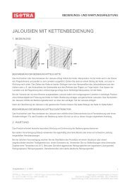
First Use – Programming and Operation1. Connect the motor to the power supply via 12-24 V DC / 0.6 A adapter2. End stop setupThe panels are required to movetowards the motor first. Pushingthe program button on the motor,the direction of the panelmove will change.Program button1 sec.Briefly push the programbuttonThe panel blind movesslowly and seeks the endstopsThe panel blind is ready fornormal use.Joint Configuration with remote control / channel (can be done using “single select” – see the Remote Control Manual).1 sec.Set the programming mode:Briefly press the Program button(1 sec.)Programming mode:The panel blind moves slowly(in single steps)Select the channel by pressingthe Channel Select button.ConfigurationResetJoint configuration of the panelblind with channel, on which thepanel blind is programmed, canbe reset.Confirm by pressing the ProgrambuttonProgramming Mode Exit:Briefly press the Program buttonNormal Use> 2 sec.Press the Program button formore than 2 sec.The panel blind will start moving afterpressing the button (max. 15 sec.)To move the panel blind in theopposite direction, press theProgram button again for morethan 2 sec.Factory Setting Reset1 sec.10 sec.Set the programming mode:Briefly press the Program buttonProgramming mode:The panel blind movesKeep pressing the Program buttonfor 10 sec. until the panel blind stopsmoving (in single steps) and untilthe last move.Factory Setting Reset and Reset of alljoint-confi gured channels / remotecontrols1 sec. 15 sek.Set the programming mode:Briefly press the Program buttonProgramming mode:The panel blind movesThe panel blind starts moving. Keeppressing the Program button for max.15 sec. until the panel blind stops moving(in single steps) and until the last move.6
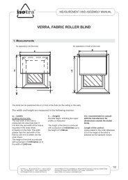
<strong>JAPANESE</strong> <strong>PANEL</strong> <strong>BLINDS</strong>Japanese Panel BlindsMeasuring InstructionsJapanese panel blinds are suitable for mounting to window hole (ceiling) orbefore the window hole (wall).W: total width of japanese panelWe produce the width of japanese panel blinds in accuracy of mm from thewidth of 1000 mm to 5800 mm with tolerance of ± 1 mm.HH: total height including the carrying profileWe produce the height of japanese panel blinds in accuracy of mm from thewidth of 1000 mm to 3200 mm with tolerance of ± 1 mm.Note: It´s necessary to consult the choice of fabric with producer for heightover 2700 mm.AWA: Overlaping of fabric (mm)Standard overlaping of fabrics is 50 mm.B: width of panel (mm)It´s necessary to indicate the width of panel in case the head rail is longer thenshaded surface - always necessary to consult with producer.HMaximal dimensions of each panel is limited by the dimension limit of particularfabrics.ASHADED SURFACEWBDetermination of the dimensions of each panel depends on the type of headrail, or more precisely on the number of panels and total width of system.Dimensions over the standard limits is necessary to consult with producer.Japanese Panel BlindsInstallation InstructionsCeiling attachmentsOther ceiling attachment typesWall brackets7
Number of attachmentsWidth (mm)Number of Attachments< 1000 21000 - 1800 31800 - 2600 42600 - 3400 53400 - 4200 65000 - 5800 7The carrying brackets to be connected using the PTC33C2, PTC33C3, PTC33C4, PTC33C5 connectors.Installation of Carrying BracketsFinal Installation of Panels8
<strong>JAPANESE</strong> <strong>PANEL</strong> <strong>BLINDS</strong>ConfigurationsPack on the leftFront sideFront sidePack on the rightPack on the leftFront sideFront sidePack on the rightPack on the left and rightFront sideTwo packs on the rightFront side9
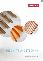
Safety features according to the standards EN 13120+A1; EN 16 433; EN 16 434Connection Pulley Winch Two wheelsSafe type of operationDangerous operationSuitability of ISOTRAprotective systemsINTERIOR SHADINGHORIZONTAL <strong>BLINDS</strong>ISOTRA SYSTEM HITISOTRA SYSTEM HIT IIISOTRA SYSTEM CLASSICISOTRA ENERGYISOLITEISOLITE PLUSNEOISOLITESYSTEM 25S, 25SMSYSTEM 25RSYSTEM 25L (large)SYSTEM 25KSYSTEM 25SWSYSTEM 25MCETTA 35, 50 - ECONOMYCETTA 35CETTA 50 (usage in interior)WOODLITE 50V-LITE INTERIOR ROOF BLINDVERTICAL <strong>BLINDS</strong><strong>JAPANESE</strong> <strong>PANEL</strong> <strong>BLINDS</strong>PLISSÉType AOType ABType BOType BBType PBFABRIC ROLLER <strong>BLINDS</strong>VERRAVERA METALROLLITELUNASUNLITENEMOSHADING ROLLER BLINDR-LITE ROOF ROLLER BLINDManuallyWheelHandleSwitchRemote controlStrapControl barCordCord/RodBall-chainConnectionPulleyWinchTwo wheels10
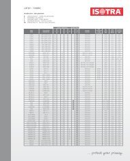
ISOTRA a.s.Bílovecká 2411/1, 746 01 OpavaCzech RepublicISOTRA PartnerTel.: +420 553 685 111Fax: +420 553 685 110E-mail: isotra@isotra.czwww.isotra.czReleased: 09/201412