BRICKMOULD AND FLUSH FLANGE WINDOWS - Pella.com
BRICKMOULD AND FLUSH FLANGE WINDOWS - Pella.com
BRICKMOULD AND FLUSH FLANGE WINDOWS - Pella.com

Create successful ePaper yourself
Turn your PDF publications into a flip-book with our unique Google optimized e-Paper software.
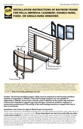
PELLA INSTALLATION INSTRUCTIONS<br />
<strong>BRICKMOULD</strong> <strong>AND</strong> <strong>FLUSH</strong> <strong>FLANGE</strong> <strong>WINDOWS</strong><br />
THE FOLLOWING INSTALLATION METHODS ARE INCLUDED IN THIS BOOKLET:<br />
New Construction Installation of Wood Brickmould Windows in Wood Framed Walls<br />
After Building Wrap<br />
New Construction Installation in Masonry Construction for Flush Flange or Wood<br />
Brickmould Windows<br />
Pocket Replacement into Aluminum Frames in Stucco Walls for Flush Flange Windows<br />
Full Frame replacement<br />
Full Frame Replacement of wood brickmould products with new <strong>Pella</strong>® EnduraClad®<br />
Exterior Trim or Wood Brickmould Products<br />
Full Frame Replacement in Stucco Walls for Flush Flange Windows<br />
Full Frame Replacement in Masonry Construction with Stucco for flush flange windows<br />
These instructions were developed and tested for use with wall systems designed to manage water.<br />
These instructions are not to be used with any other construction methods or window frame types.<br />
Installation instructions for use with other construction methods or frame types may be obtained from<br />
<strong>Pella</strong> Corporation, your local <strong>Pella</strong> retailer or www.installpella.<strong>com</strong>. Building designs, construction<br />
methods, building materials, and site conditions unique to your project may require an installation<br />
method different from these instructions and/or additional care. Determining the appropriate<br />
installation method is the responsibility of you, your architect, or construction professional.<br />
Always read the Limited Warranty before purchasing or installing <strong>Pella</strong>® products. By installing this product, you are acknowledging<br />
that this Limited Warranty is part of the terms of the sale. Failure to <strong>com</strong>ply with all <strong>Pella</strong> installation and maintenance instructions<br />
may void your <strong>Pella</strong> product warranty. See Limited Warranty for <strong>com</strong>plete details at http://warranty.pella.<strong>com</strong>.<br />
BMFF – 1<br />
Revised 06/29/2014 © 2014 <strong>Pella</strong> Corporation BM-FF_Booklet
FULL FRAME OR SASH REMOVAL WHEN PREPARING TO INSTALL A NEW WINDOW WITH<br />
<strong>BRICKMOULD</strong> OR <strong>FLUSH</strong> <strong>FLANGE</strong><br />
CAUTION: Many windows in older homes are painted with lead-based paint. Removal of old windows may disturb this paint. Proper<br />
precautions must be taken to minimize exposure to dust and debris. Consult state or local authorities and/or go to www.epa.gov/lead<br />
for more information.<br />
TOOLS REQUIRED:<br />
• Utility knife<br />
• Pry bar<br />
• Hammer<br />
• Heat gun<br />
• Angle grinder<br />
• Phillips and Standard<br />
• Reciprocating saw<br />
• Putty knife<br />
• Deglazing wheel<br />
screwdrivers<br />
REMEMBER TO USE APPROPRIATE PERSONAL PROTECTIVE EQUIPMENT.<br />
Apply adhesive film or duct tape to the glass to prevent breakage.<br />
B<br />
ALUMINUM SASH <strong>AND</strong>/OR FRAME REMOVAL<br />
A. Score the paint or varnish between the interior trim and the wall or<br />
between the drywall return and the window frame to minimize damage.<br />
(Frame removal only).<br />
B. Remove the interior trim.<br />
C. Score the sealant or paint between the exterior siding or brick and the<br />
window frame.<br />
D. Remove the screen and vent sash from the old window. If it is not<br />
removable, see steps G-I.<br />
E. Remove the division bar by removing the screws at the ends or cutting it<br />
with a reciprocating saw.<br />
F. Remove the other sash/panel. Remove any screws holding the fixed sash.<br />
Slide it and lift it out of the channel (sliding windows) or tilt it and release it<br />
from the balance assembly (hung windows).<br />
If the sashes are not removable or the glass is sealed to the frame:<br />
G. Remove the glazing bead using a putty knife or small pry bar.<br />
H. For single pane windows with divided lights (grids). Use an angle grinder<br />
with a cut-off wheel to cut the end of the bars where they intersect with<br />
the sash or frame. This will allow the window glass to be removed more<br />
quickly.<br />
I. Heat the glazing seal using an electric heat gun.<br />
J. While applying heat, press a de-glazing wheel between the glass and<br />
sash or frame. Continue around the perimeter of the sash or panel. Apply<br />
light, constant pressure to separate the glass from the sash or frame.<br />
Dispose or recycle of the glass properly.<br />
NOTE: Wear appropriate personal protective equipment and keep the<br />
heat source away from flammable materials.<br />
E<br />
G<br />
I<br />
H<br />
H<br />
J<br />
Stop here for pocket replacement, <strong>com</strong>plete steps K-L for full frame<br />
replacement.<br />
K. Cut through the frame using a reciprocating saw.<br />
L. Pry the frame away from the brick or siding. Use a block of wood under<br />
the pry bar to protect interior or exterior finishes. Dispose or recycle of the<br />
frame materials properly.<br />
L<br />
K<br />
<strong>BRICKMOULD</strong> FRAME REMOVAL<br />
A. Score paint or varnish between the interior trim and the wall with a sharp utility knife.<br />
NOTE: This will minimize the damage to the interior wall and trim.<br />
B. Remove the interior trim. Remove the interior trim from all the four sides of the window<br />
including the stool at the bottom of the window. If the interior trim is being reused, pull<br />
the nails out through the back side of the board with nipper pliers.<br />
C. Cut the exterior sealant line between the exterior brickmould or trim and the exterior<br />
siding or wall cladding.<br />
D. Remove the exterior brickmould or flat trim.<br />
CAUTION: Some windows may <strong>com</strong>e out of the opening as the exterior trim is removed.<br />
NOTE: DO NOT disturb existing head flashings.<br />
E. Remove the window frame.<br />
B<br />
D<br />
BMFF – 2<br />
Consult with local providers and authorities to recycle or properly dispose of old window <strong>com</strong>ponents.<br />
Revised 06/29/2014 © 2014 <strong>Pella</strong> Corporation BM-FF_Booklet
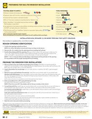
PREPARING FOR <strong>BRICKMOULD</strong> OR <strong>FLUSH</strong> <strong>FLANGE</strong> WINDOW INSTALLATION.<br />
YOU WILL NEED TO SUPPLY:<br />
• Moisture Resistant shims/spacers<br />
• Fasteners (see frame anchor instructions at the end of this booklet)<br />
• Closed cell foam backer rod/sealant backer<br />
• <strong>Pella</strong>® SmartFlash foil backed butyl window and door flashing tape or equivalent.<br />
• Low expansion, low pressure polyurethane insulating window and door foam sealant<br />
DO NOT use high pressure or latex foams.<br />
• <strong>Pella</strong> Window and Door Installation Sealant or equivalent high quality, multi-purpose<br />
sealant (1 tube per window)<br />
SEALANT<br />
Note: Other construction materials may be required. Read and understand the<br />
instructions and inspect the wall conditions before you begin.<br />
TOOLS REQUIRED:<br />
• Tape measure<br />
• Level<br />
• Square<br />
• Hammer<br />
• Scissors or utility knife<br />
• Small flat blade screwdriver<br />
• Sealant Gun<br />
• Screw Gun with a Phillips Driver bit<br />
• 1/8" Allen wrench<br />
Store windows in upright position, out of direct sunlight.<br />
PREPARING FOR INSTALLATION<br />
TWO OR MORE PEOPLE WILL BE REQUIRED FOR THE WINDOW INSTALLATION.<br />
A. Remove plastic wrap and cardboard packaging from the window. Do not<br />
cut checkrail bands (if present) or remove plastic or foam shipping spacers<br />
located between the window sash and frame. DO NOT open the window<br />
until it is securely fastened.<br />
B. Inspect the product for any damage such as cracks, dents or scratches. DO<br />
NOT install damaged windows.<br />
C. Remove screens and hardware (if necessary). Label them and set aside in a<br />
protected area.<br />
Windows with Half Screens: From the exterior, pull one side of the screen<br />
near the shipping clips until the clips disengage from the frame. Rotate the<br />
shipping clips toward the exterior of the screen until they snap free from the<br />
screen.<br />
Half screens of some vinyl windows can be removed from the interior.<br />
D. Pre-Drill Installation holes or install clips (if necessary). See frame anchor<br />
instructions at the end of this booklet."<br />
E. Before Installation, remove dirt and debris from all surfaces of the opening.<br />
F. Read the entire instruction before proceeding.<br />
#6 x 5/8” corrosion<br />
resistant screws<br />
Lip<br />
D<br />
D<br />
DISCARD<br />
PUSH<br />
DISCARD<br />
PUSH<br />
Shipping<br />
Clip<br />
C<br />
6“ from end<br />
Pull screen near<br />
shipping clip<br />
C<br />
C<br />
These instructions were developed and tested for use with wall systems designed to manage water. These instructions are not to be used with any other<br />
construction methods or window frame types. Installation instructions for use with other construction methods or frame types may be obtained from <strong>Pella</strong><br />
Corporation, your local <strong>Pella</strong> retailer or www.installpella.<strong>com</strong>. Building designs, construction methods, building materials, and site conditions unique to your<br />
project may require an installation method different from these instructions and/or additional care. Determining the appropriate installation method is the<br />
responsibility of you, your architect, or construction professional.<br />
Always read the Limited Warranty before purchasing or installing <strong>Pella</strong>® products. By installing this product, you are acknowledging<br />
that this Limited Warranty is part of the terms of the sale. Failure to <strong>com</strong>ply with all <strong>Pella</strong> installation and maintenance instructions<br />
may void your <strong>Pella</strong> product warranty. See Limited Warranty for <strong>com</strong>plete details at http://warranty.pella.<strong>com</strong>.<br />
BMFF – 3<br />
Revised 06/29/2014 © 2014 <strong>Pella</strong> Corporation BM-FF_Booklet
WOOD <strong>BRICKMOULD</strong> WINDOW AFTER BUILDING WRAP—FOR USE IN WOOD FRAME WALLS.<br />
Water Resistive Barrier<br />
Sheathing<br />
Framing<br />
Sill Flashing Tape #1<br />
Sill Flashing Tape #2<br />
1 PREPARE THE OPENING 2 SETTING <strong>AND</strong> FASTENING THE WINDOW<br />
Refer to the installation preparation section at the beginning of this<br />
booklet.<br />
A. Confirm the window will fit<br />
the opening. Measure all<br />
four sides of the opening<br />
to make sure it is 1/2" to<br />
3/4" larger than the window<br />
in both width and height 1B 1C<br />
including subsill. On larger<br />
openings; measure the<br />
width and height in several<br />
places to ensure the header<br />
or studs are not bowed.<br />
NOTE: 1-1/2" or more of solid<br />
wood blocking is required<br />
around the perimeter of the<br />
opening.<br />
Fix any problems with the rough<br />
opening before proceeding.<br />
B. Cut the building wrap. Refer to<br />
the diagram for other window<br />
shapes.<br />
Water Resistive Barrier<br />
1st cut<br />
6” 6”<br />
3rd cut<br />
2nd<br />
cut<br />
Exterior<br />
1C 1D<br />
C. Fold the building wrap in at the<br />
jambs and staple it in place. Fold the top flap up<br />
and temporarily fasten with flashing tape.<br />
D. Cut 2 pieces of flashing tape 12" longer than<br />
opening width.<br />
E. Apply sill flashing tape #1 at the sill extending 1" to<br />
the exterior and 6" up each jamb.<br />
F. Cut 1" wide tabs at each corner by tearing the foil<br />
1/2" each way from corner.<br />
G. Apply sill flashing tape #2 overlapping tape #1 by<br />
1" minimum.<br />
NOTE: Press all tape down firmly.<br />
H. Install and level sill shims. Place 1" wide x 1/4" to<br />
3/8" thick shims 1/2" from each side. Keep shims<br />
back 1/2" from the interior face of the window. Place<br />
additional shims under each mullion and sliding<br />
window interlocker.<br />
I. Attach shims to prevent movement after they are<br />
level.<br />
NOTE: Improper placement of shims may result in<br />
bowing the bottom of the window.<br />
1"<br />
6"<br />
1E 1F<br />
Water Resistive Barrier<br />
1/2"<br />
1"<br />
Exterior<br />
1/2"<br />
1 st cut<br />
6”<br />
2 nd 6”<br />
cut<br />
1B 1C<br />
3 rd cut<br />
1C 1D<br />
1D 1E<br />
1F<br />
1G<br />
1H 2A<br />
A. Apply sealant to the back of the brickmould or flat casing.<br />
B. Insert the window into the opening by placing the window sill on the sill<br />
spacers and tilting the window up. Center the window between jambs.<br />
INTERIOR<br />
2A<br />
C. Level the window across the head. Adjust the sill<br />
shims as necessary.<br />
D. Drive 16d galvanized finished nails at each upper<br />
corner through the brickmould and into the wood<br />
framing.<br />
E. Plumb and square the window using shims at the<br />
locations shown. Adjust shims to plumb and square<br />
the window. Keep shims 1/2" short of window<br />
frame depth.<br />
53”<br />
or less<br />
Interior<br />
2E<br />
1”<br />
Mid<br />
1”<br />
Interior View<br />
For windows over 53” tall.<br />
EXTERIOR<br />
2B<br />
#16 galvanized<br />
finishing nails<br />
EXTERIOR<br />
2C<br />
NOTE: DO NOT shim above the window or between the sill shims.<br />
Additional shims are required at screw locations for large units and<br />
<strong>com</strong>binations. See the anchor instructions at the end of this booklet.<br />
2E<br />
2D<br />
BMFF – 4<br />
Revised 06/29/2014 © 2014 <strong>Pella</strong> Corporation BM-FF_Booklet
WOOD <strong>BRICKMOULD</strong> WINDOW AFTER BUILDING WRAP (CONTINUED)<br />
Aluminum Head<br />
Flashing<br />
Corner<br />
Flashing<br />
Tapes<br />
Top<br />
Flashing<br />
Tape<br />
Water Resistive Barrier<br />
Sheathing<br />
Framing<br />
Water Resistive Barrier<br />
Sheathing<br />
Framing<br />
2<br />
SETTING<br />
<strong>AND</strong> FASTENING THE WINDOW<br />
(CONTINUED)<br />
F. Check window operation.<br />
Vent awning and casement: See lock<br />
lever and crank handle instructions<br />
at the end of this instruction. Lift<br />
the lock lever and turn the crank<br />
handle to open the window. Remove<br />
the shipping spacers. Open and<br />
close the window to test for proper<br />
operation.<br />
Double Hung: Cut the checkrail<br />
bands (if applicable) and remove<br />
shipping spacers. Open, close and tilt the sashes to test<br />
for proper operation. Check for equal sash to frame reveal<br />
from top to bottom.<br />
NOTE: Adjust shims to correct any issues with<br />
plumb, square, operation or reveal.<br />
G. Close and lock the window.<br />
H. Finish driving 16d galvanized finish nails<br />
through the brickmould. Space nails 4" max.<br />
from corners and 10" apart between nails.<br />
Interior View<br />
2F<br />
#16 galvanized<br />
finishing nails<br />
2H<br />
3 INTEGRATING WITH THE BUILDING WRAP<br />
A. Apply a bead of sealant along the top of the brickmould where it meets<br />
the wall. Continue the sealant along the edges of the brickmould to the<br />
front corner.<br />
B. Install Head Flashing by pressing it into the sealant and securing it to the<br />
wall using roofing nails.<br />
C. Cut a piece of flashing tape 4" longer than the brickmould width.<br />
D. Apply the flashing tape over the head flashing<br />
and onto the sheathing so it extends past the<br />
Flashing tape<br />
brickmould 2" each side.<br />
3B<br />
Head flashing<br />
Head flashing<br />
Sealant<br />
3B<br />
3D<br />
E. Fold down top flap of weather resistive<br />
barrier.<br />
F. Apply flashing tape to top diagonal cuts.<br />
Cut pieces of flashing tape at least 1"<br />
longer than each diagonal cut. Lap tape<br />
1" past end of cut onto weather barrier.<br />
Overlap multiple pieces of tape by 1"<br />
when necessary.<br />
3F<br />
EXTERIOR<br />
3E<br />
Exterior<br />
3F<br />
3C<br />
Building Wrap Cutting Patterns for Window Shapes<br />
3F 3C<br />
<br />
<br />
<br />
<br />
<br />
NOTE: PRESS ALL FLASHING TAPE DOWN FIRMLY.<br />
G. Install interior sealant. Refer to the interior sealant instructions at the end<br />
of this booklet.<br />
<br />
<br />
<br />
<br />
<br />
<br />
H. Install exterior sealant. (After wall cladding is installed) Refer to the<br />
exterior sealant instructions at the end of this booklet.<br />
BMFF – 5<br />
Revised 06/29/2014 © 2014 <strong>Pella</strong> Corporation BM-FF_Booklet
<strong>BRICKMOULD</strong> OR <strong>FLUSH</strong> <strong>FLANGE</strong> <strong>WINDOWS</strong> INTO MASONRY CONSTRUCTION — ONTO<br />
WOOD BUCK <strong>AND</strong>/OR PRE-CAST CONCRETE SILLS<br />
1 PREPARE THE OPENING<br />
Refer to the installation preparation section at the<br />
beginning of this booklet.<br />
A. Apply water resistant coating. Extend the coating<br />
into the opening on all four sides and onto the<br />
wall surface at least 9". The water resistant coating<br />
may be a self-adhered sheet membrane (SASM)<br />
or a liquid applied flashing. Ensure continuity<br />
between the water resistant coating in the opening<br />
and the rest of the wall surface. SASM ’s must be<br />
overlapped in a water shed fashion. Apply all water<br />
resistant coatings according to the manufacturer’s<br />
directions.<br />
NOTE: Allow liquid flashing to dry according to the<br />
manufacturer’s re<strong>com</strong>mendations.<br />
B. Apply 2 beads of sealant to the masonry opening<br />
where the wood buck will be attached.<br />
NOTE: Ensure the sealant is <strong>com</strong>patible with the<br />
water resistant coating.<br />
C. Pre-drill and fasten the treated wood buck to the<br />
masonry opening using code-approved fasteners.<br />
D. Apply water resistant coating (optional) over the<br />
wood buck and onto the masonry opening. If using<br />
liquid applied flashing, allow it to dry according<br />
to the manufacturer’s<br />
re<strong>com</strong>mendations before<br />
proceeding.<br />
1D<br />
For Vinyl windows with 1/2" or<br />
5/8" flanges on Pre-Cast Concrete<br />
sills, use steps 1G, 1H, and 1I.<br />
E. Install and level sill shims.<br />
Place 1" wide x 1/4" to 3/8"<br />
thick shims 1/2" from each side. Keep shims back<br />
1/2" from interior face of window. Place additional<br />
shims under each mullion and sliding window<br />
interlocker.<br />
For vinyl windows, add shims so maximum<br />
spacing is 18".<br />
F. Attach shims to prevent movement after they are<br />
level.<br />
NOTE: Improper placement of shims may result in<br />
bowing the bottom of the window.<br />
G. Apply a continuous, 3/8" tall bead of sealant on<br />
the surface of the buck where the Flush Flange or<br />
Brickmould will be placed at the sides and top only.<br />
Do NOT apply sealant at the sill.<br />
Proceed to Step 2.<br />
Exterior<br />
Interior<br />
Interior<br />
Interior<br />
Interior<br />
1G<br />
1A<br />
Concrete block<br />
1B<br />
1C<br />
1E<br />
Interior<br />
1 PREPARE THE OPENING (CONTINUED)<br />
Vinyl windows with 1/2" or 5/8" flanges on Precast Concrete Sills.<br />
H. Place two 3/8" beads of sealant on the precast sill. Place the first bead<br />
1-1/2" from the exterior edge of the sill. Place the second bead 1/2" from<br />
the exterior edge of the sill.<br />
Exterior<br />
1-1/2"<br />
1/2"<br />
1H<br />
I. Place a bead of sealant on the front edge of the precast sill, connecting it<br />
to the bead of sealant on the surface of the wood buck.<br />
2 PREPARE THE WINDOW<br />
FRAME SCREW INSTALLATION<br />
A. Prepare the frame (if applicable).<br />
Remove interior frame covers—Impervia casement.<br />
Remove the vent track—350 Series sliding window sill.<br />
Remove the sill riser—350 Series double hung and single hung.<br />
B. Drill pilot holes (if necessary) in the new window frame. See the anchor<br />
instructions at the end of this booklet.<br />
NOTE: WHERE POSSIBLE, USE FRAME SCREWS AT THE SILL TO AVOID<br />
PENETRATING THE INTERIOR SEAL. DO NOT SCREW THROUGH THE SILL<br />
WHEN A SILL TRACK IS PART OF THE WINDOW’S WEEP SYSTEM.<br />
CLIP INSTALLATION<br />
C. Pre-bend clips if anchors will be installed into the interior wall surface<br />
(Metal clips only).<br />
See the anchor spacing instructions at the end of this booklet.<br />
D. Secure clips to the window frame:<br />
Sill accessory groove<br />
Attachment<br />
clip<br />
2D 1E<br />
SLIDING WINDOW SILL<br />
1I<br />
En<strong>com</strong>pass by <strong>Pella</strong>®/Thermastar by <strong>Pella</strong>®/<strong>Pella</strong>®250 Series<br />
BMFF – 6<br />
Revised 06/29/2014 © 2014 <strong>Pella</strong> Corporation BM-FF_Booklet
<strong>BRICKMOULD</strong> OR <strong>FLUSH</strong> <strong>FLANGE</strong> <strong>WINDOWS</strong> INTO MASONRY CONSTRUCTION<br />
(CONTINUED)— ONTO WOOD BUCK <strong>AND</strong>/OR PRE-CAST CONCRETE SILLS<br />
Exterior<br />
Exterior<br />
2 PREPARE THE WINDOW (CONTINUED)<br />
E. Slide clips into the frame grooves.<br />
NOTE: Pre-bend clips if anchors will be installed into the interior wall<br />
surface (Metal clips only).<br />
F. Secure the clips to the frame. Use a small piece of flashing tape to<br />
prevent the clips from sliding out of place (<strong>Pella</strong>® Impervia®). Drive two<br />
#8x1/2" pan head screws (provided) into the first row of pre-punched<br />
holes in the clip (All <strong>Pella</strong>® 350 Series head and jambs except sliding<br />
windows. Do not install screws at the sill.).<br />
2E<br />
Interior<br />
Top View<br />
Architect Series (850), Designer Series (750) and Proline (450)<br />
G. Install the clips into the fin grooves. Start one corner of the clip in the fin<br />
groove. Tap the corner into the fin groove with a hammer, then continue to<br />
tap the other corner until the clip is locked into the groove.<br />
H. Secure the clips to the frame. Drive one #8 x 5/8" screw through the<br />
slotted hole in the center of the clip.<br />
2G<br />
Frame<br />
head<br />
groove<br />
Frame<br />
sill<br />
groove<br />
<strong>Pella</strong>® Impervia® and <strong>Pella</strong>® 350 Series<br />
Fin groove<br />
Frame<br />
jamb<br />
groove<br />
Alternatively, it is acceptable to use<br />
two #8 x 5/8" screws through the<br />
clip with the clip on its back and not<br />
engaged in the fin groove.<br />
2G<br />
Lip<br />
#6 x 5/8” corrosion<br />
resistant screws<br />
2H<br />
2F<br />
6“ from end<br />
3 SET <strong>AND</strong> FASTEN THE WINDOW<br />
A. Insert the window into the opening by<br />
placing the front edge of the window sill on<br />
the opening sill and tilting the window up.<br />
Center the window between jambs.<br />
B. Wood Brickmould units only: Drive 16d<br />
galvanized finished nails at each upper<br />
corner through the brickmould and into the<br />
wood buck.<br />
C. Place sealant under each clip (if applicable).<br />
D. Place shims and begin driving screws at<br />
each predrilled hole in the window frame or<br />
each clip. Install masonry screws at least 2"<br />
from wall edge.<br />
Refer to the anchor instructions at the end of<br />
this booklet.<br />
NOTE: Ensure the window flange or brickmould<br />
remains firmly embedded in sealant.<br />
Keep shims 1/2" from the interior surface of the<br />
window to allow for a continuous interior seal.<br />
E. Cut the checkrail band at each jamb and<br />
remove. Tilt the sashes to remove checkrail clips.<br />
(If applicable)<br />
<strong>Pella</strong>® ProLine/450 only: Push the remaining<br />
tails of the band into the jambliner holes.<br />
F. Check for plumb, level, square and window<br />
operation. Make any necessary adjustments to<br />
shims and finish installing frame screws or clip<br />
anchors.<br />
G. Adjust the screw jacks (if applicable) with a<br />
screwdriver. Turn clockwise to move the frame<br />
toward the sash.<br />
Tilt the lower sash inward to locate the jamb<br />
jacks in the interior balance channel near the<br />
checkrail.<br />
G. Install interior sealant. Refer to the interior<br />
sealant instructions at the end of this booklet.<br />
Use additional sealant around clips to prevent<br />
air and water infiltration.<br />
H. Install exterior sealant between the edge of<br />
the flush flange or brickmould and the finished<br />
wall material. Refer to the exterior sealant<br />
instructions at the end of this booklet.<br />
3F<br />
INTERIOR<br />
3D 2C<br />
3F 2B<br />
3A<br />
3D<br />
3C<br />
BMFF – 7<br />
Revised 06/29/2014 © 2014 <strong>Pella</strong> Corporation BM-FF_Booklet
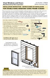
POCKET REPLACEMENT WITH <strong>FLUSH</strong> <strong>FLANGE</strong>—FOR THE INSTALLATION OF NEW <strong>FLUSH</strong> <strong>FLANGE</strong> <strong>WINDOWS</strong> IN<br />
EXISTING ALUMINUM FRAMES WITH STUCCO WALLS IN ARID CLIMATES<br />
Existing Aluminum<br />
Window Frame<br />
Flush Flange<br />
Interlocker<br />
Drain Slots<br />
1 PREPARE THE OPENING<br />
A. Measure the width and height of the<br />
opening in the remaining aluminum<br />
frame after sash/glass removal. The new<br />
window must be 1/2" to 3/4" smaller in<br />
width and height.<br />
B. Remove the sash and/or glass from<br />
the existing aluminum window. Refer<br />
to the sash removal instructions at the<br />
beginning of this booklet.<br />
C. Clean the existing frame so it is free of<br />
dirt and debris. Ensure the weep holes<br />
are open and clear.<br />
1A <br />
D. Apply sealant at the lower corners where the jamb and sill of the<br />
existing frame meet.<br />
E. Cut and/or rip wood blocking to<br />
1D<br />
fit inside the drywall return and to<br />
Sealant<br />
a depth 1/4" less than the existing<br />
frame.<br />
F. Cut one piece of flashing tape 6"<br />
longer than the existing aluminum<br />
frame width.<br />
1<br />
PREPARE<br />
THE OPENING<br />
(CONTINUED)<br />
K. Install and level sill shims. Place 1"<br />
wide x 1/4" to 3/8" thick shims 1/2"<br />
from each side. Keep shims back<br />
1/2" from the interior face of the<br />
window. Place additional shims under<br />
each mullion and sliding window<br />
1K 1D<br />
interlocker.<br />
L. Attach shims to prevent movement<br />
after they are level.<br />
NOTE: Improper placement of shims<br />
may result in bowing the bottom of<br />
the window.<br />
M. Dry fit the window into the opening from the exterior. Confirm the flush<br />
flange will overlap the existing aluminum frame or stucco by at least 3/4"<br />
on all 4 sides.<br />
<br />
<br />
G. Apply the tape over the wood<br />
blocking so it extends 1" into the first<br />
sill cavity of the existing aluminum<br />
frame and goes 3" up each jamb.<br />
H. Cut and or rip treated or <strong>com</strong>posite<br />
blocking to fit in the sill cavities of the<br />
existing aluminum frame. The height<br />
of the blocking should match the<br />
tallest leg of the existing aluminum<br />
frame.<br />
I. Cut notches in the sill filler blocking<br />
to align with the weep holes in the<br />
existing aluminum frame.<br />
J. Install the sill filler blocking into the<br />
sill cavity. Ensure the existing weeps<br />
are not blocked.<br />
Window Frame Depth minus 1/4"<br />
Flashing Tape<br />
Wood Filler<br />
Wood Blocking<br />
1G<br />
1J 1L<br />
1M <br />
<br />
<br />
NOTE: Fix any problems before proceeding.<br />
If the flange(s) must be trimmed to fit in a recessed opening, use a utility<br />
knife or circular saw for vinyl or fiberglass flanges. Use an electric scissorstyle<br />
shear for aluminum flanges.<br />
BMFF – 8<br />
Revised 06/29/2014 © 2014 <strong>Pella</strong> Corporation BM-FF_Booklet
POCKET REPLACEMENT WITH <strong>FLUSH</strong> <strong>FLANGE</strong> (CONTINUED)—FOR THE INSTALLATION OF NEW <strong>FLUSH</strong><br />
<strong>FLANGE</strong> <strong>WINDOWS</strong> IN EXISTING ALUMINUM FRAMES WITH STUCCO WALLS IN ARID CLIMATES<br />
2 PREPARE THE WINDOW<br />
A. Drill pilot holes (if necessary) in the new window frame. Refer to the<br />
anchor instructions at the end of this booklet.<br />
NOTE: Some vinyl windows require attachment clips. Refer to the<br />
anchor instructions at the end of this booklet.<br />
B. Place a 3/8" diameter bead of sealant on the exterior perimeter of the<br />
existing aluminum window frame.<br />
Leave 2" gaps in the sealant line at each weep hole.<br />
BMFF – 9<br />
2A<br />
2B 3A<br />
Accessory Groove<br />
Exterior View<br />
Attachment<br />
Clip<br />
Weep holes<br />
3 SET <strong>AND</strong> FASTEN THE WINDOW<br />
A. Insert the window into the opening by placing the<br />
front edge of the window sill on the opening sill and<br />
tilting the window up. Center the window between<br />
jambs.<br />
B. Place sealant under each clip (if applicable).<br />
C. Drill clearance holes at each pre-drilled hole in the<br />
new window frame through the existing aluminum<br />
frame.<br />
D. Place shims and begin driving screws at each<br />
predrilled hole in the window frame or each clip. Add<br />
additional shims at the ends of the meeting rails and<br />
as necessary to ensure even reveal between the frame<br />
and sashes.<br />
NOTE: Keep shims 1/2" from the interior surface<br />
of the window to allow for a continuous interior<br />
seal.<br />
Refer to the anchor instructions at the end of this<br />
booklet.<br />
NOTE: Ensure the window flange remains firmly<br />
embedded in sealant.<br />
E. Cut the checkrail band at each jamb and remove.<br />
Tilt the sashes to remove checkrail clips. (If<br />
applicable)<br />
<strong>Pella</strong>® ProLine/450 only: Push the remaining<br />
tails of the band into the jambliner holes.<br />
F. Check for plumb, level, square and window<br />
operation. Make any necessary adjustments<br />
to shims and finish installing frame screws<br />
and/or clip anchors.<br />
G. Adjust the screw jacks (if applicable) with<br />
a screwdriver. Turn clockwise to move the<br />
frame toward the sash.<br />
Tilt the lower sash inward to locate the jamb<br />
jacks in the interior balance channel near the<br />
checkrail.<br />
H. Install interior sealant. Refer to the<br />
interior sealant instructions at the end<br />
of this booklet. Use additional sealant<br />
around clips to prevent air and water<br />
infiltration.<br />
I. Install exterior sealant around<br />
the edge of the flush flange on<br />
3I<br />
all 4 sides. Leave 2" gaps in<br />
the sealant below each<br />
existing frame weep<br />
hole location.<br />
Revised 06/29/2014 © 2014 <strong>Pella</strong> Corporation BM-FF_Booklet<br />
3F<br />
Exterior<br />
Exterior View<br />
3A<br />
3F 3D<br />
2"
FULL FRAME REPLACEMENT WITH WOOD OR ENDURACLAD <strong>BRICKMOULD</strong> - FULL FRAME<br />
REPLACEMENT OF WOOD <strong>BRICKMOULD</strong> <strong>WINDOWS</strong> WITH NEW PELLA® ENDURACLAD® EXTERIOR TRIM OR WOOD<br />
<strong>BRICKMOULD</strong> PRODUCTS<br />
Sill Flashing Tape #1<br />
Sill Flashing Tape #2<br />
1 PREPARE THE OPENING<br />
Refer to the brickmould frame removal instructions at the beginning<br />
of this booklet.<br />
A. Measure the width and height of the brick/siding opening and the rough<br />
opening. The new brickmould must be 1/2" to 3/4" smaller than the brick/<br />
siding opening. The new window frame must be 1/2" to 3/4" smaller than<br />
the rough opening.<br />
B. Repair the wall surface around the opening (if necessary) by installing<br />
new blocking flush with the surface of the existing sheathing. Repair the<br />
existing building wrap with by cutting it flush with the rough opening and<br />
covering any gaps with flashing tape.<br />
Applications with Building Wrap<br />
C. Install head flashing by applying sealant to the back of the upturned leg<br />
and inserting the upturned leg behind the building wrap as shown.<br />
HEAD<br />
1<br />
PREPARE<br />
THE OPENING<br />
(CONTINUED)<br />
In place of the existing wood subsill, install a sloped sill. (Steps F-J).<br />
F. Cut an approx. 1/4" thick spacer equal to<br />
the width of the rough opening. Reduce the<br />
thickness (if necessary) to maintain enough<br />
opening height for window installation. Set the<br />
spacer along the interior of the sill.<br />
G. Cut 3/4" thick blocking (typically a 1x6) equal<br />
to the width of the rough opening.<br />
H. Apply a 1/4" diameter bead of sealant along<br />
the sides and front edge of the opening sill.<br />
I. Apply a bead of low expansion foam along the center of the<br />
rough opening sill.<br />
J. Set and fasten the 3/4" thick blocking on the spacer with nails or<br />
screws creating a sloped surface.<br />
1H<br />
Foam<br />
Spacer<br />
1C<br />
1I<br />
1J<br />
Applications without Building Wrap (steps D and E).<br />
D. Cut a piece of flashing tape equal to the width of the rough opening.<br />
E. Apply the tape across the top of the rough opening so it extends onto the<br />
surface of the wall at least 1".<br />
1D<br />
1"<br />
Sealant<br />
K. Cut 2 pieces of flashing tape 12" longer than opening width.<br />
L. Apply sill flashing tape #1 at the sill extending 1" to the exterior<br />
and 6" up each jamb.<br />
M. Cut 1" wide tabs at each corner by tearing the foil 1/2" each way<br />
from corner.<br />
N. Apply sill flashing tape #2 overlapping tape #1 by 1" minimum.<br />
NOTE: Press all tape down firmly.<br />
1E<br />
1"<br />
1"<br />
6"<br />
1L<br />
1N<br />
1/2"<br />
1/2"<br />
1M<br />
BMFF – 10<br />
Revised 06/29/2014 © 2014 <strong>Pella</strong> Corporation BM-FF_Booklet
FULL FRAME REPLACEMENT WITH WOOD OR ENDURACLAD <strong>BRICKMOULD</strong> (CONTINUED)<br />
1<br />
PREPARE<br />
THE OPENING<br />
(CONTINUED)<br />
O. Install and level wedge shaped sill shims. Place<br />
1" wide x 1/4" to 3/8" thick shims 1/2" from<br />
each side. Place additional shims under each<br />
mullion. Keep shims back 1/2" from the interior<br />
face of the window. Use wedge shaped shims<br />
to make a level surface for the window to set<br />
on.<br />
P. Attach shims to prevent movement after they<br />
are level.<br />
NOTE: Improper placement of shims may result<br />
in bowing the bottom of the window.<br />
2 PREPARE THE WINDOW<br />
A. Remove the packaging. Leave installation straps in<br />
place. (Enduraclad exterior trim only) Installation<br />
straps aide in pulling the brickmould tight against<br />
the wall surface.<br />
B. For frame screw attachment; drill pilot holes in the<br />
window frame.<br />
C. For installation clip attachment; use two #8 x 5/8"<br />
screws through the clip with the clip on its back.<br />
Refer to the screw spacing instructions at the end of<br />
this booklet.<br />
BMFF – 11<br />
#6 x 5/8” corrosion<br />
resistant screws<br />
3 SET <strong>AND</strong> FASTEN THE WINDOW<br />
A. Place a continuous 3/8" bead of sealant<br />
on the surface of the wall where the<br />
brickmould will be placed. Leave 2"<br />
gaps near each jamb along the sill.<br />
Lip<br />
3A<br />
2C<br />
Straps<br />
2A<br />
Cardboard<br />
2A 1O<br />
6“ from end<br />
3<br />
SET<br />
<strong>AND</strong> FASTEN THE WINDOW<br />
(CONTINUED)<br />
B. Insert the window into the opening by<br />
placing the front edge of the window<br />
sill on the opening sill and tilting the<br />
window up. Center the window between<br />
jambs.<br />
C. Wood Brickmould units only: Drive 16d<br />
galvanized finished nails at each upper<br />
corner through the brickmould and into<br />
the wood buck.<br />
D. Cut the cord to free up the installation<br />
straps (Enduraclad exterior trim only)<br />
and use a quick grip clamp with reversed<br />
jaws to push against the wall and pull the<br />
window against the opening.<br />
E. Place sealant under each clip (if<br />
applicable).<br />
F. Place shims and begin driving<br />
screws at each predrilled hole<br />
in the window frame or each<br />
clip. Use the quick grip clamp<br />
to fully embed the brickmould<br />
in the sealant and to make the<br />
distance from the interior of<br />
the new window to the surface<br />
of wall equal all around the<br />
window.<br />
Refer to the anchor instructions at<br />
the end of this booklet.<br />
Keep shims 1/2" from the interior surface of the<br />
window to allow for a continuous interior seal.<br />
G. Cut the checkrail band at each jamb and remove.<br />
Tilt the sashes to remove checkrail clips. (If<br />
applicable)<br />
<strong>Pella</strong>® ProLine/450 only: Push the remaining tails<br />
of the band into the jambliner holes.<br />
H. Check for plumb, level, square and window<br />
operation. Make any necessary adjustments to<br />
shims and finish installing frame screws or clip<br />
anchors.<br />
I. Install interior sealant. Refer to the interior<br />
sealant instructions at the end of this booklet.<br />
Use additional sealant around clips to prevent air<br />
and water infiltration (if applicable).<br />
3<br />
INTERIOR VIEW<br />
J. Install exterior sealant between the edge of the<br />
brickmould and the finished wall material. Refer to the exterior sealant<br />
instructions at the end of this booklet.<br />
Revised 06/29/2014 © 2014 <strong>Pella</strong> Corporation BM-FF_Booklet<br />
INTERIOR<br />
3F 3C<br />
3D<br />
in<br />
2<br />
1<br />
3F<br />
3H 3D<br />
3F<br />
NOTE
FULL FRAME REPLACEMENT IN STUCCO WITH <strong>FLUSH</strong> <strong>FLANGE</strong>—ROUGH OPENING PREPARATION USING<br />
WATER MANAGEMENT LINER (PATENT PENDING)<br />
Liners<br />
Jamb<br />
Flashing<br />
Tapes<br />
Filler Strip<br />
Sill Flashing Tape<br />
1 REMOVE THE EXISTING WINDOW 2 PREPARE THE OPENING<br />
CAUTION: Many windows in older homes are painted with lead-based<br />
paint. Removal of old windows may disturb this paint. Proper precautions<br />
must be taken to minimize exposure to dust and debris. Consult state or<br />
local authorities for more information.<br />
REMEMBER TO USE APPROPRIATE PERSONAL PROTECTIVE EQUIPMENT.<br />
A. Measure the width and height of the opening inside the drywall return.<br />
The new window frame size must be at least 1/2” to 3/4” smaller than this<br />
measurement.<br />
B. Cut through the existing window nailing fin on all sides. Cut against the<br />
edge of the frame with an angle grinder or circular saw with diamond<br />
blade. Use a reciprocating saw to finish the cutting the corners. Be careful<br />
not to chip or crack the stucco.<br />
NOTE: Use a vacuum with a HEPA filter to minimize dust while cutting.<br />
A. Place a 3/8" bead of sealant<br />
(or enough to cover the area)<br />
between the stucco and the<br />
wood framing at the jambs and<br />
sill. Do not seal across the top.<br />
B. Press the sealant into<br />
irregularities and smooth it with<br />
a putty knife.<br />
C. Place a 3/8" bead of sealant<br />
at each corner of the opening<br />
from the stucco to the interior<br />
edge of the rough opening.<br />
2A<br />
2B<br />
JAMBS<br />
<strong>AND</strong><br />
SILL<br />
ONLY<br />
2B<br />
TOOL<br />
SEALANT<br />
INTO<br />
OPENING<br />
EXTERIOR - STUCCO<br />
2C<br />
Drywall Return<br />
1B<br />
1B<br />
EXTERIOR - STUCCO<br />
1B<br />
Maintain a safe distance between the vacuum and power tool.<br />
C. Remove the existing window and dispose of it properly.<br />
D. Make any modifications or repairs to the opening at this time.<br />
E. Cut the stucco and existing window fin along the opening sill to ensure<br />
the stucco does not project above the sill framing.<br />
D. Cut one piece of flashing tape 12" longer than the width of the rough<br />
opening.<br />
E. Apply the tape across the sill and 6" up each jamb. Press the tape down<br />
firmly over the stucco, exposed sealant and up the surface of drywall.<br />
F. Cut 2 pieces of tape equal to the height of the rough opening.<br />
G. Apply the pieces at each jamb in the same manner as the sill, overlapping<br />
the sill tape.<br />
FLASHING TAPE<br />
PLACEMENT GUIDE<br />
1E<br />
2E<br />
Drywall Return<br />
JAMB TAPES<br />
F. Clean the rough opening by vacuuming all dust and debris.<br />
2G<br />
SILL TAPE<br />
BMFF – 12<br />
Revised 06/29/2014 © 2014 <strong>Pella</strong> Corporation BM-FF_Booklet
Foam<br />
FULL FRAME REPLACEMENT IN STUCCO WITH <strong>FLUSH</strong> <strong>FLANGE</strong> (CONTINUED)—ROUGH OPENING<br />
PREPARATION USING WATER MANAGEMENT LINER (PATENT PENDING)<br />
Stucco<br />
HEAD<br />
Drywall<br />
Insulating<br />
Foam<br />
Insulating Foam<br />
EXTERIOR - STUCCO<br />
Drywall<br />
No Sealant<br />
Below Drains<br />
Stucco<br />
SILL<br />
2 PREPARE THE OPENING (CONTINUED)<br />
H. Cut a 1/2" thick wood or <strong>com</strong>posite filler<br />
strip equal to the rough opening width. Stucco<br />
Rip it to a width equal No to Sealant the distance<br />
Below Drains<br />
from the exterior surface of drywall to the<br />
surface of the stucco – 1-5/8".<br />
I. Apply a 3/8" bead of sealant across the<br />
sill on top of the flashing tape against the<br />
drywall and along the end.<br />
J. Set the filler strip in the sealant and<br />
secure it with screws 6" from the ends and<br />
every 16".<br />
2" 1"<br />
Flashing<br />
Tape<br />
Drywall<br />
Return<br />
Filler Strip<br />
Sill Liner<br />
Drywall<br />
Return<br />
K. Cut the aluminum extruded sill liner equal to the width of the rough<br />
opening.<br />
L. Cut 1" wide weep slots 2" from each end.<br />
2L<br />
M. Apply two lines of 3/8" sealant across the<br />
opening sill and join them at the ends.<br />
N. Secure the sill liner over the sealant with<br />
1.25" self-drilling pan head screws 6" from<br />
the ends and every 12".<br />
O. Apply Sealant along each end of the sill<br />
liner.<br />
P. Fill any gaps with sealant along the joint<br />
between the stucco and the bottom of the<br />
sill liner.<br />
Q. Tool the sealant smooth. Remove excess<br />
sealant below the weep slots.<br />
2I<br />
2K<br />
2I<br />
2M<br />
2O<br />
SILL<br />
Insulating Foam<br />
Drywall<br />
2L<br />
1"<br />
Flashing<br />
Tape<br />
Sill Liner<br />
2"<br />
Drywall<br />
Return<br />
Filler Strip<br />
Drywall<br />
Return<br />
2 PREPARE THE OPENING (CONTINUED)<br />
R. Cut the head liner equal to the opening<br />
width.<br />
S. Make 1/4" deep by 3/4" wide tabs,<br />
bending them down as shown.<br />
T. Apply a 3/8" bead of sealant across<br />
the top of the opening 1-3/4" from the<br />
surface of the stucco and 1" down the<br />
sides.<br />
U. Secure the head liner over the sealant<br />
using self-drilling screws 6" from ends<br />
and every 12". The liner may be shifted<br />
to allow the stucco to extend below the<br />
rough opening.<br />
2U<br />
Stucco<br />
Stucco<br />
Sealant<br />
Drywall<br />
HEAD LINER (Flush Mount)<br />
Sealant<br />
Drywall<br />
HEAD LINER (Overlap Mount)<br />
V. Cut two jamb liners to fit between the<br />
head and sill liners.<br />
W. Apply 3/8" beads of sealant down each<br />
jamb 1-3/4" from the surface of the<br />
stucco.<br />
X. Secure the jamb liner over the sealant<br />
using self-drilling screws 6" from ends<br />
and every 12". The liner may be shifted<br />
to allow the stucco to extend below the<br />
rough opening.<br />
Y. Seal the upper corners where the head<br />
and jamb liners meet.<br />
Z. Seal the lower corners at the interior leg<br />
only.<br />
AA.Place <strong>com</strong>posite shims in the sill liner<br />
under the location where the installation<br />
shims will be installed.<br />
BB.Refer to the Pocket Replacement with<br />
Flush Flange instruction beginning at step 1 K in this booklet to<br />
<strong>com</strong>plete the installation.<br />
2S<br />
TAB<br />
2T<br />
DO NOT<br />
seal the<br />
tab area<br />
2X<br />
3G<br />
1-3/4“<br />
Flashing<br />
Tape<br />
Head Liner<br />
2W<br />
Jamb<br />
Liner<br />
Jamb<br />
Liner<br />
Head Liner<br />
Drywall<br />
Return<br />
2Z<br />
Sill Liner<br />
2AA<br />
Do not<br />
seal drain<br />
channel<br />
Sill Liner<br />
3G<br />
BMFF – 13<br />
Revised 06/29/2014 © 2014 <strong>Pella</strong> Corporation BM-FF_Booklet
FULL FRAME REPLACEMENT IN MASONRY CONSTRUCTION WITH STUCCO FOR <strong>FLUSH</strong><br />
<strong>FLANGE</strong> <strong>WINDOWS</strong><br />
Wood Buck<br />
Flashing Tape<br />
1 PREPARE THE OPENING<br />
Refer to the full frame removal instruction at the<br />
beginning of this booklet.<br />
A. Measure the width and height of the opening.<br />
The window must be approximately 1/2" smaller<br />
in width and height.<br />
If replacing a wood buck, trim back any finish<br />
materials to ac<strong>com</strong>modate the new wood bock.<br />
B. Apply 2 beads of sealant to the masonry opening<br />
where the wood buck will be attached.<br />
C. Fasten the treated wood buck to the masonry<br />
opening using code-approved fasteners.<br />
D. Apply sealant at the corners of the wood buck<br />
and at the intersection of the wood buck and<br />
stucco.<br />
E. Apply flashing tape from the stool over the top of<br />
the pre-cast concrete sill and 6" up each side.<br />
F. Apply water resistant coating or flashing<br />
tape over the wood buck. If using liquid<br />
applied flashing, allow it to dry according to<br />
the manufacturer’s re<strong>com</strong>mendations before<br />
proceeding.<br />
G. Install and level sill shims. Place 1" wide x 1/4" to<br />
3/8" thick shims 1/2" from each side. Keep shims<br />
back 1/2" from interior face of window. Place<br />
additional shims under each mullion and sliding<br />
window interlocker.<br />
For vinyl windows, add shims so maximum<br />
spacing is 18".<br />
H. Attach shims to prevent movement after they<br />
are level.<br />
NOTE: Improper placement of shims may result in<br />
bowing the bottom of the window.<br />
I. Measure the opening in the stucco and the size of<br />
the window to the tip of the flanges. If necessary,<br />
trim the flange.<br />
For Vinyl windows with 1/2" or 5/8" flanges on Pre-<br />
Cast Concrete sills use steps 1J, 1K, and 1L if there is<br />
not enough space for shims. If sill shims were used,<br />
skip to step 2.<br />
J. Apply a continuous, 3/8" tall bead of sealant on<br />
the surface of the buck where the Flush Flange<br />
will be placed at the sides and top only.<br />
Do NOT apply sealant at the sill.<br />
Proceed to Step 2.<br />
1D<br />
1E<br />
Interior<br />
1J<br />
1B<br />
1A<br />
1G<br />
1 PREPARE THE OPENING (CONTINUED)<br />
K. Place two 3/8" beads of sealant on the precast sill. Place the first bead<br />
1-1/2" from the exterior edge of the sill. Place the second bead 1/2" from<br />
the exterior edge of the sill.<br />
L. Place a bead of sealant on the front edge of the precast sill, connecting it<br />
to the bead of sealant on the surface of the wood buck.<br />
1-1/2"<br />
1/2"<br />
1K 1H<br />
2 PREPARE THE WINDOW<br />
FRAME SCREW INSTALLATION<br />
A. Prepare the frame (if applicable).<br />
Remove interior frame covers—Impervia casement.<br />
Remove the vent track—350 Series sliding window sill.<br />
Remove the sill riser—350 Series double hung and single hung.<br />
B. Drill pilot holes (if necessary) in the new window frame. See the anchor<br />
instructions at the end of this booklet.<br />
NOTE: WHERE POSSIBLE, USE FRAME SCREWS AT THE SILL TO AVOID<br />
PENETRATING THE INTERIOR SEAL. DO NOT SCREW THROUGH THE SILL<br />
WHEN A SILL TRACK IS PART OF THE WINDOW’S WEEP SYSTEM.<br />
CLIP INSTALLATION<br />
C. Pre-bend clips if anchors will be installed into the interior wall surface<br />
(Metal clips only).<br />
See the anchor spacing instructions at the end of this booklet.<br />
D. Secure clips to the window frame:<br />
En<strong>com</strong>pass by <strong>Pella</strong>®/Thermastar by <strong>Pella</strong>®/<strong>Pella</strong>®250 Series<br />
Sill accessory groove<br />
Attachment<br />
clip<br />
2D 1E<br />
SLIDING WINDOW SILL<br />
1I<br />
1L<br />
BMFF – 14<br />
Revised 06/29/2014 © 2014 <strong>Pella</strong> Corporation BM-FF_Booklet
FULL FRAME REPLACEMENT IN MASONRY CONSTRUCTION WITH STUCCO FOR <strong>FLUSH</strong><br />
<strong>FLANGE</strong> <strong>WINDOWS</strong> (CONTINUED)<br />
2 PREPARE THE WINDOW (CONTINUED)<br />
E. Slide clips into the frame grooves.<br />
NOTE: Pre-bend clips if anchors will be installed into the interior wall<br />
surface (Metal clips only).<br />
F. Secure the clips to the frame. Use a small piece of flashing tape to<br />
prevent the clips from sliding out of place (<strong>Pella</strong>® Impervia®). Drive two<br />
#8x1/2" pan head screws (provided) into the first row of pre-punched<br />
holes in the clip (All <strong>Pella</strong>® 350 Series head and jambs except sliding<br />
windows. Do not install screws at the sill.).<br />
2E<br />
Interior<br />
Top View<br />
Architect Series (850), Designer Series (750) and Proline (450)<br />
G. Install the clips into the fin grooves. Start one corner of the clip in the fin<br />
groove. Tap the corner into the fin groove with a hammer, then continue to<br />
tap the other corner until the clip is locked into the groove.<br />
H. Secure the clips to the frame. Drive one #8 x 5/8" screw through the<br />
slotted hole in the center of the clip.<br />
2G<br />
Frame<br />
head<br />
groove<br />
Frame<br />
sill<br />
groove<br />
<strong>Pella</strong>® Impervia® and <strong>Pella</strong>® 350 Series<br />
Fin groove<br />
Frame<br />
jamb<br />
groove<br />
Alternatively, it is acceptable to use<br />
two #8 x 5/8" screws through the<br />
clip with the clip on its back and not<br />
engaged in the fin groove.<br />
2G<br />
Lip<br />
#6 x 5/8” corrosion<br />
resistant screws<br />
2H<br />
2F<br />
6“ from end<br />
3 SET <strong>AND</strong> FASTEN THE WINDOW<br />
A. Insert the window into the opening by placing<br />
the front edge of the window sill on the opening<br />
sill and tilting the window up. Center the window<br />
between jambs.<br />
B. Place sealant under each clip (if applicable).<br />
C. Place shims and begin driving screws at each<br />
predrilled hole in the window frame or each clip.<br />
Install masonry screws at least 2" from wall edge.<br />
Refer to the anchor instructions at the end of this<br />
booklet.<br />
NOTE: Ensure the window flange or brickmould<br />
remains firmly embedded in sealant.<br />
Keep shims 1/2" from the interior surface of the<br />
window to allow for a continuous interior seal.<br />
D. Cut the checkrail band at each jamb and<br />
remove. Tilt the sashes to remove checkrail clips.<br />
(If applicable)<br />
<strong>Pella</strong>® ProLine/450 only: Push the remaining<br />
tails of the band into the jambliner holes.<br />
E. Check for plumb, level, square and window<br />
operation. Make any necessary adjustments to<br />
shims and finish installing frame screws or clip<br />
anchors.<br />
F. Adjust the screw jacks (if applicable) with a<br />
screwdriver. Turn clockwise to move the frame<br />
toward the sash.<br />
Tilt the lower sash inward to locate the jamb<br />
jacks in the interior balance channel near the<br />
checkrail.<br />
G. Install interior sealant. Refer to the interior<br />
sealant instructions at the end of this booklet.<br />
Use additional sealant around clips to prevent<br />
air and water infiltration.<br />
H. Install exterior sealant between the edge of<br />
the flush flange or brickmould and the finished<br />
wall material. Refer to the exterior sealant<br />
instructions at the end of this booklet.<br />
3C 2C<br />
Exterior<br />
3E 2B<br />
3H<br />
3C<br />
3A<br />
BMFF – 15<br />
Revised 06/29/2014 © 2014 <strong>Pella</strong> Corporation BM-FF_Booklet<br />
2"
<strong>FLUSH</strong> <strong>FLANGE</strong> <strong>AND</strong> <strong>BRICKMOULD</strong> FRAME WINDOW ANCHOR INSTRUCTIONS<br />
Note: Standard performance only. Additional anchoring may be required for performance upgrade, impact resistant products or to <strong>com</strong>ply<br />
with local building code requirements.<br />
PLACE FRAME SCREWS OR CLIPS AT THE LOCATIONS INDICATED<br />
E<br />
EVERY<br />
S<br />
E<br />
M2 M2 EVERY<br />
E S S<br />
M1 M1<br />
M2<br />
M1<br />
M2<br />
M1<br />
S<br />
E<br />
E<br />
EVERY<br />
S<br />
E<br />
E<br />
EVERY<br />
S<br />
M2<br />
M1<br />
M2<br />
M1<br />
S<br />
E<br />
E<br />
E<br />
E<br />
E<br />
S<br />
EVERY<br />
S<br />
E<br />
EVERY<br />
S<br />
E<br />
M1<br />
M1<br />
M2<br />
M2<br />
EVERY<br />
S<br />
EVERY<br />
S<br />
M1<br />
M1<br />
M2<br />
M2<br />
E<br />
EVERY<br />
S<br />
E<br />
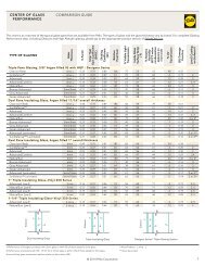
ARCHITECT SERIES® (850), DESIGNER SERIES® (750) <strong>AND</strong> PELLA® PROLINE (450) WINDOW ANCHOR SPACING INSTRUCTIONS<br />
Product<br />
Edge<br />
Spacing<br />
(E)<br />
Max.<br />
Intermediate<br />
Spacing<br />
(S)<br />
First<br />
Mullion<br />
Anchor<br />
(M1)<br />
Second<br />
Mullion<br />
Anchor<br />
(M2)<br />
Fastener<br />
Wood **<br />
Special Notes<br />
Casement / Awning 6" 16" 3"* 6" #8x3" Finish Screw<br />
Double- or<br />
Single- Hung<br />
6" 16" 3"* 6" #8x3" Finish Screw<br />
Fixed Frame 6" 16" 3"* 6" #8x3" Finish Screw<br />
** = For light gauge steel framing, use #10 self-drilling/self-tapping screws; For concrete or masonry, use 3/16" masonry screws<br />
with 1-1/4" minimum embedment.<br />
* = M1 anchor required if design pressure exceeds 20 psf.<br />
PILOT HOLE LOCATIONS <strong>AND</strong> SIZES<br />
Casement Head<br />
Double-Hung Head<br />
Double-Hung Head<br />
Clad Frame Head<br />
Drill 1/8"<br />
clearance<br />
hole<br />
1/2"<br />
Drill 1/8"<br />
clearance hole<br />
Drill 1/8"<br />
clearance hole<br />
1"<br />
Drill 1/8"<br />
clearance hole<br />
Casement Jamb<br />
Drill 1/8"<br />
clearance<br />
hole<br />
Double-Hung Jamb<br />
Double-Hung Jamb<br />
Drill 1/8"<br />
clearance hole<br />
1"<br />
Clad Frame Sill<br />
1/4"<br />
Drill 1/8"<br />
clearance hole<br />
Drill 1/8"<br />
clearance hole<br />
Drill 1/8"<br />
clearance hole<br />
Drill 1/8"<br />
clearance hole<br />
Drill 1/8"<br />
clearance hole<br />
1/2"<br />
Casement Sill<br />
Double-Hung Sill<br />
Double-Hung Sill<br />
BMFF – 16<br />
Revised 06/29/2014 © 2014 <strong>Pella</strong> Corporation BM-FF_Booklet
<strong>FLUSH</strong> <strong>FLANGE</strong> <strong>AND</strong> <strong>BRICKMOULD</strong> FRAME WINDOW ANCHOR INSTRUCTIONS (CONT.)<br />
Note: Standard performance only. Additional anchoring may be required for performance upgrade, impact resistant products or to <strong>com</strong>ply<br />
with local building code requirements.<br />
PELLA® IMPERVIA WINDOW ANCHOR SPACING INSTRUCTIONS<br />
Product<br />
Edge<br />
Spacing (E)<br />
Max.<br />
Intermediate<br />
Spacing (S)<br />
First Mullion Second Mullion<br />
Anchor (M1) Anchor (M2)<br />
Fastener<br />
Wood**<br />
Casement / Awning 6"* 16"* None 6" #8 x 3" Pan Head (provided)<br />
Single-Hung / Sliding<br />
Window<br />
6"* 16"* None 6" #8 x 3" Pan Head (provided)<br />
Double-Hung 6"* 16"* None 6" #8 x 3" Pan Head (provided)<br />
Special Notes<br />
Head and Sill anchors not required<br />
when frame width < 42"<br />
Do not use Frame screws<br />
through the sill.<br />
Fixed Frame 6"* 16"* None 6" #8 x 3" Pan Head (provided)<br />
* = Use Factory Drilled installation holes if present.<br />
** = For light gauge steel framing, use #10 self-drilling/self-tapping screws; For concrete or masonry, use 3/16" masonry screws with 1-1/4"<br />
minimum embedment.<br />
Install hole plugs after driving screws.<br />
3/16"<br />
Removable<br />
Frame Cover<br />
3/8"<br />
PILOT HOLE LOCATIONS <strong>AND</strong> SIZES<br />
3/8"<br />
3/8"<br />
3/8"<br />
Exterior<br />
3/16"<br />
Exterior<br />
5/32"<br />
Exterior<br />
5/32"<br />
Exterior<br />
5/32"<br />
Exterior<br />
5/32"<br />
Plug<br />
Casement**<br />
Double-Hung<br />
Sliding Window<br />
Single-Hung<br />
** If an Interior Frame Cover has a “Quick Release Band” around the cover; pull the band to help remove the cover.<br />
Fixed Frame<br />
PELLA® 350 SERIES WINDOW ANCHOR SPACING INSTRUCTIONS<br />
Product<br />
Edge<br />
Spacing (E)<br />
Max.<br />
Intermediate<br />
Spacing (S)<br />
First Mullion<br />
Anchor (M1)<br />
Second<br />
Mullion<br />
Anchor (M2)<br />
Fastener<br />
Wood**<br />
Special Notes<br />
Casement / Awning 6"* 16"* None 6" #10 x 3" Pan Head (provided)<br />
Sliding and Fixed<br />
Window<br />
Double- and<br />
Single-Hung<br />
6"* 16"* None 6" #10 x 3" Pan Head (provided)<br />
6"* 16"* None 6" #10 x 3" Pan Head (provided)<br />
Place 2 screws 4" from the center of the meeting rail<br />
at the head and sill of sliding windows.<br />
* = Use Factory Drilled installation holes if present.<br />
** = For light gauge steel framing, use #10 self-drilling/self-tapping screws; For concrete or masonry, use 3/16" masonry screws with 1-1/4"<br />
minimum embedment.<br />
Install hole plugs after driving screws.<br />
PILOT HOLE LOCATIONS <strong>AND</strong> SIZES<br />
3/8"<br />
Insert<br />
Screwdriver<br />
EXTERIOR<br />
INTERIOR<br />
EXTERIOR<br />
INTERIOR<br />
BMFF – 17<br />
Casement<br />
3/8"<br />
Remove sill riser<br />
(if applicable)<br />
5/32"<br />
Double/Single Hung<br />
5/32"<br />
1<br />
2<br />
Press<br />
Insert<br />
Screwdriver<br />
Exterior<br />
Remove vent track<br />
(if applicable)<br />
Sliding Window<br />
EXTERIOR<br />
3/8"<br />
SILL<br />
5/32"<br />
Sliding Window<br />
1-1/4"<br />
INTERIOR<br />
EXTERIOR<br />
SILL<br />
Fixed Window<br />
SILL<br />
Fixed Window<br />
Revised 06/29/2014 © 2014 <strong>Pella</strong> Corporation BM-FF_Booklet<br />
3/8"<br />
INTERIOR<br />
5/32"<br />
1/8" Allen<br />
wrench<br />
SILL
<strong>FLUSH</strong> <strong>FLANGE</strong> <strong>AND</strong> <strong>BRICKMOULD</strong> FRAME WINDOW ANCHOR INSTRUCTIONS (CONT.)<br />
Product<br />
15 Series Double-Hung<br />
20 Series Sliding Window<br />
(East and West)<br />
20 Series Single-Hung<br />
(West)<br />
20 Series Single- and<br />
Double-Hung (East)<br />
20 Series Casement / Awning<br />
and Fixed<br />
Note: Standard performance only. Additional anchoring may be required for performance upgrade, impact resistant products or to <strong>com</strong>ply<br />
with local building code requirements.<br />
ENCOMPASS BY PELLA®/THERMASTAR BY PELLA® /PELLA® 250 SERIES <strong>FLUSH</strong> <strong>FLANGE</strong> FRAME ANCHOR SPACING INSTRUCTIONS<br />
Edge<br />
Spacing (E)<br />
Max. Intermediate<br />
Spacing (S)<br />
Factory<br />
Pre-Drilled<br />
First Mullion<br />
Anchor (M1)<br />
Second<br />
Mullion<br />
Anchor (M2)<br />
6" 16" 3" / centered 8" / none<br />
6" 16" 3" 6"<br />
Factory<br />
Pre-Drilled**<br />
Fastener<br />
Wood***<br />
4" / 6" 8" / none #8 x 2" Pan Head (provided)<br />
#8 x 1-1/4" Pan Head<br />
(provided)<br />
#8 x 2-1/2" Pan Head<br />
(provided)<br />
4" 8" #10 x 2" Pan Head (provided)<br />
4"* 16"* 4" none #8 x 3" Pan Head (provided)<br />
250 DH/SH (single units) Factory Pre-Drilled** --- --- #10 x 2" Pan Head (provided)<br />
250 DH / SH / FX 4" 16" ** 3" 6"<br />
250 SW 4" 16" --- 6"<br />
250 SW ≥PG50 4" 12" --- 6"<br />
All venting products: Head and sill anchors are required on <strong>com</strong>posites only.<br />
* Use Factory Drilled installation holes if present.<br />
** For DH & SH units >62" tall add 2 screws per jamb, midway between top and bottom pre-drilled holes.<br />
*** For light gauge steel framing, use #10 self-drilling/self-tapping screws; for concrete or masonry, use<br />
3/16" masonry screws with 1-1/4" minimum embedment.<br />
#10 x 2" Pan Head (provided)<br />
Special Notes<br />
Use 2 clips at the sill 6"<br />
each side of mullions<br />
Use M1 and M2 spacing for screws at head of<br />
meeting rail. Center 1 clip below the<br />
meeting rail.<br />
Use M1 and M2 spacing for screws at the head<br />
only with mullions.<br />
Use M1 and M2 spacing for screws at head and<br />
clips at sill with mullions only.<br />
Use clips at the sill at mullions and centered<br />
under fixed casements in 3-wide <strong>com</strong>binations.<br />
Use self-adhesive spacer at all installation holes<br />
for ≥ PG50 Performance Installs<br />
Use M1 and M2 spacing for screws at head and<br />
clips at sill with mullions only. Use self-adhesive<br />
spacer at all installation holes for ≥ PG50<br />
Performance Installs<br />
250 Series DH PG50 ONLY: Add additional clip at center of mullion at sill only.<br />
Install hole plugs/caps after driving screws. Replace all covers, fillers and tracks removed earlier.<br />
Attachment<br />
clip<br />
Sill accessory groove<br />
Attachment<br />
clip<br />
PILOT HOLE LOCATIONS <strong>AND</strong> SIZES<br />
250 Series<br />
Allen Wrench<br />
3/8”<br />
1/2” 1/2”<br />
Drill (2) 5/32"holes<br />
3/8” from the edge<br />
in each clip.<br />
Plug<br />
SLIDING WINDOW SILL<br />
20 Series Casement/<br />
Awning and Fixed<br />
SW Vent Track<br />
SW Pocket Filler<br />
20 Series Single Hung (West)<br />
Take-out clip<br />
Take-out clip<br />
Take-out clip<br />
Take-out clip<br />
Balance hook<br />
EXTERIOR<br />
Balance hook<br />
EXTERIOR<br />
JAMB<br />
JAMB<br />
3/8"<br />
3/8"<br />
30º<br />
Balance<br />
Balance<br />
Tie Bar Tie Bar<br />
Before drilling jamb<br />
installation holes, pull out<br />
the bottom of the take-out<br />
clip on each jamb.<br />
Balance hook<br />
Tie Bar Tie Bar<br />
Raise the sash until the<br />
balance engages the<br />
take-out clips. Slide the<br />
sash all the way to one<br />
side and pull out the<br />
JAMB<br />
opposite side. Carefully<br />
set the sash aside.<br />
EXTERIOR<br />
Bottom<br />
end guide<br />
Bottom<br />
end guide<br />
Tie Bar<br />
Tie Bar<br />
Open venting windows to access screw holes.<br />
Loosen the tie bar guides and remove the tie<br />
bar to access screw holes (if necessary).<br />
3/8" 3/8"<br />
5/32" 5/32"<br />
3/8" 3/8"<br />
30º 30º<br />
5/32" 5/32"<br />
INTERIOR<br />
INTERIOR<br />
Self Adhesive spacer<br />
PG50 Frame Filler<br />
5/32"<br />
20 Series Fixed Window<br />
Pocket Cover Removal<br />
5/32"<br />
Separate the balances<br />
from the take out clips<br />
by holding them at top<br />
and bottom and pushing<br />
down 1". Tilt the top of<br />
the balance away from the<br />
frame and lift the hook out<br />
of the frame.<br />
BMFF – 18<br />
INTERIOR<br />
Drill<br />
3/16"<br />
holes<br />
Single Wall Flush<br />
Flange Venting<br />
Windows Tie Bar<br />
Drill<br />
3/16"<br />
holes<br />
Tie Bar<br />
Venting<br />
Window<br />
West Fixed<br />
Window<br />
Remove fixed window glazing beads<br />
before drilling installation holes. (West)<br />
Revised 06/29/2014 © 2014 <strong>Pella</strong> Corporation BM-FF_Booklet<br />
3/8"<br />
5/32"<br />
2B<br />
FIXED WINDOW<br />
3/8"<br />
30º<br />
3/16" (Drill at slight<br />
angle towards interior)<br />
1/2" (Counter-drill at<br />
slight angle towards interior)<br />
5/8"<br />
2D<br />
5/32"<br />
1/2" drill bit with<br />
drill guide placed<br />
1/4" from end of bit.<br />
Glazing Bead
INTERIOR <strong>AND</strong> EXTERIOR SEALANT<br />
Interior Sealant Instructions<br />
CAUTION: Use low pressure polyurethane window and door insulating foams. Follow the directions<br />
on the can. Do not use high pressure or latex foams.<br />
A. Insert the nozzle or straw between the rough opening and window frame. This can be done from the<br />
interior or exterior.<br />
B. Place a 1" deep bead of foam approx. 1" from the interior of the frame to allow for expansion. DO<br />
NOT fill the entire depth of the rough opening cavity.<br />
NOTE: Apply foam between the frame and rough opening, NOT between jamb extensions and the<br />
rough opening.<br />
C. To ensure a continuous interior seal, apply sealant over the interior surface of any shims or clips<br />
interrupting the foam seal.<br />
Backer rod (as necessary) and sealant can be used in place of the low expansion foam to create the<br />
interior seal. However, foam has greater insulating properties. Fiberglass batt or similar insulation is<br />
not re<strong>com</strong>mended as it can absorb water and does not act as an air seal.<br />
Use sealant instead of foam at all 4 sides on the interior of 1/2" flange vinyl windows installed in<br />
masonry construction with pre-cast sills. Add backer rod if the gap exceeds 3/16"<br />
NOTE: Use a low odor, paintable sealant such as <strong>Pella</strong> Window and<br />
Door Installation Sealant.<br />
Re-check window operation and remove shipping spacers after foam<br />
installation. Excess foam may be removed with a serrated knife after<br />
it cures.<br />
Backer rod<br />
and<br />
sealant typical<br />
Interior<br />
4A<br />
3/16" or<br />
greater<br />
Less than<br />
3/16"<br />
1/4” Min.<br />
Exterior Sealant Instructions<br />
CAUTION: Use a high quality, multi-purpose exterior sealant such as <strong>Pella</strong> Window and Door Installation<br />
Sealant. Follow the directions on the cartridge.<br />
Flush Flange Windows<br />
Place a corner bead of sealant on the top, sides and bottom of the window along the edge of the flush<br />
flange where it meets the stucco. Leave a 2" gap in the sealant bead at the bottom below the weep hole<br />
location in the existing aluminum frame.<br />
Exterior<br />
Brickmould Windows<br />
If the space between the new window brickmould and the opening is less than 1/4", go to step (B).<br />
A. Insert backer rod 3/8" deep in the space around the window. Backer rod adds shape and controls the<br />
depth of the sealant line.<br />
B. Apply a continuous bead of sealant to the entire perimeter of the window.<br />
C. Shape, tool and clean excess sealant. When finished, the sealant should be the shape of an hourglass.<br />
2"<br />
BRICK VENEER<br />
Backer Rod and<br />
Sealant typical<br />
3/8" Clearance<br />
WOOD SIDING<br />
WITH TRIM<br />
Backer Rod and<br />
Sealant typical<br />
3/8" Clearance<br />
Insulate<br />
and<br />
seal per<br />
Step 5<br />
Insulate<br />
and<br />
seal per<br />
Step 5<br />
Flush flange<br />
3/8"<br />
3/8"<br />
Corner bead<br />
BMFF – 19<br />
Revised 06/29/2014 © 2014 <strong>Pella</strong> Corporation BM-FF_Booklet
Installing Roto Cover and Crank<br />
Note: Finish the interior of the window and allow the window to dry before<br />
proceeding with these instructions. (To open the window for finishing,<br />
partially insert the lock handle into the jamb, unlock<br />
the unit, temporarily attach the crank handle and<br />
Pocket End<br />
turn to open.)<br />
A. Place the cover over the operator stud and snap<br />
into place. Position the pocket end of the cover into<br />
place.<br />
Screw Hole<br />
Note: If the cover does not have the screw hole,<br />
apply pressure on the pocket end of the cover to<br />
snap the cover into place and proceed to step C.<br />
B. Insert the provided screw into the hole in the<br />
bottom of the pocket. Use a # 1 Phillips screwdriver<br />
to secure the pocket screw snug against the bottom<br />
of the pocket to avoid scratching the crank handle<br />
knob. DO NOT over tighten.<br />
C. Use a medium size flat-blade screwdriver to loosen<br />
A<br />
B<br />
Operator Stud<br />
the set screw in the crank handle.<br />
Crank Handle<br />
D<br />
D. Slide the crank handle onto the stud. Unlock, open<br />
window, then close and lock window.<br />
E. Fold the crank handle down and check alignment<br />
Operator Stud<br />
of knob with the pocket.<br />
Note: You may need to adjust the crank position on<br />
Set Screw C<br />
the stud until the correct alignment is achieved.<br />
F. Open the crank and tighten the set screw.<br />
G. After the final installation, fold the crank over and<br />
snap the knob into the pocket.<br />
Note: Even with the window open the crank can<br />
Knob<br />
E<br />
be folded to avoid interferring with the window<br />
Pocket<br />
treatments.<br />
Lock Lever Installation and Removal<br />
A. Unlock and open the window.<br />
B. Place the lock lever in the locked<br />
position.<br />
C. From the exterior of the window, insert a<br />
small flat-blade screwdriver into the slot<br />
behind the lock lever.<br />
D. Pry the cam away from the side of the<br />
window by rotating the screwdriver a<br />
quarter turn. This will release the hook in<br />
the lever from the cam hook.<br />
E. Remove the lock lever by pulling it<br />
toward the interior of the building.<br />
F. To install a lock lever, hold it in the lock<br />
position and insert it, from the interior,<br />
into the slot until it snaps into the cam.<br />
Interior Frame Cover<br />
removed to show<br />
orientation of<br />
screwdriver between<br />
the lever and cam.<br />
B Interior Exterior C F<br />
Interior<br />
E<br />
Exterior Finish of Existing Frame (Pocket Replacement)<br />
It is the responsibility of the homeowner, contractor or installer to ensure any exposed unfinished wood is covered or finished. Possible methods include, however are not limited to,<br />
covering with aluminum coil stock or painting.<br />
Cleaning Instructions<br />
GLASS—Remove any protective film and labels and clean the glass, using a soft, clean, grit-free cloth and mild soap or detergent. Be sure to remove all liquid by wiping dry or use a<br />
clean squeegee.<br />
PELLA® ALUMINUM CLAD OR IMPERVIA FRAMES—The interior and exterior frame and sash are protected with a tough factory finish. Clean this surface with mild soap and water.<br />
Stubborn stains and deposits may be removed with mineral spirits. DO NOT use abrasives. DO NOT scrape or use tools that might damage the surface.<br />
ENCOMPASS BY PELLA®/THERMASTAR BY PELLA® <strong>AND</strong> PELLA® 250 SERIES <strong>WINDOWS</strong> FRAMES—The vinyl frame may be cleaned using the same method as the glass. For stubborn<br />
dirt, a “non-abrasive" cleaner such as Bon-Ami® or Soft Scrub® may be used. Do not use solvents such as mineral spirits, toluene, xylene, naphtha or muriatic acid as they can dull the<br />
finish, soften the vinyl and/or cause failure of the insulated unit seal. Keep door tracks clear of dirt and debris. Keep weep holes open and clear of obstructions.<br />
Use of inappropriate solvents, brickwash or cleaning chemicals will cause adverse reactions with window and door materials and voids the Limited Warranty.<br />
Interior Finish (Wood Windows)<br />
If products cannot be finished immediately, cover with clear plastic to protect from dirt, damage and moisture. Remove any construction residue before finishing. Sand all wood<br />
surfaces lightly with 180 grit or finer sandpaper. DO NOT use steel wool. BE CAREFUL NOT TO SCRATCH THE GLASS. Remove sanding dust. <strong>Pella</strong> products must be finished per the<br />
below instructions; failure to follow these instructions voids the Limited Warranty.<br />
• On casement and awnings, it is optional to paint, stain or finish the vertical and horizontal sash edges.<br />
• On single-hungs and double-hungs, do not paint, stain or finish the vertical sash edges, any finish on the vertical sash edges may cause the sash to stick; it is optional to paint,<br />
stain or finish the horizontal sash edges.<br />
Note: To maintain proper product performance do not paint, finish or remove the weatherstripping, mohair dust pads, gaskets or vinyl parts. Air and water leakage will<br />
result if these parts are removed. After finishing, allow venting windows and doors to dry <strong>com</strong>pletely before closing them.<br />
<strong>Pella</strong> Corporation is not responsible for interior paint and stain finish imperfections for any product that is not factory-applied by <strong>Pella</strong> Corporation. For additional information on<br />
finishing see the <strong>Pella</strong> Owner’s Manual or go to www.pella.<strong>com</strong>.<br />
Care and Maintenance<br />
Care and maintenance information is available by contacting your local <strong>Pella</strong> retailer. This information is also available at www.pella.<strong>com</strong>.<br />
IMPORTANT NOTICE<br />
Because all construction must anticipate some water infiltration, it is important that the wall system be designed and constructed to properly manage moisture. <strong>Pella</strong> Corporation<br />
is not responsible for claims or damages caused by anticipated and unanticipated water infiltration; deficiensies in building design, construction and maintenance; failure to install<br />
<strong>Pella</strong> products in accordance with <strong>Pella</strong>’s installation instructions; or the use of <strong>Pella</strong> products in wall systems which do not allow for proper management of moisture within the wall<br />
systems. The determination of the suitability of all building <strong>com</strong>ponents, including the use of <strong>Pella</strong> products, as well as the design and installation of flashing and sealing systems are<br />
the responsibility of the Buyer or User, the architect, contractor, installer, or other construction professional and are not the responsibility of <strong>Pella</strong>.<br />
<strong>Pella</strong> products should not be used in barrier wall systems which do not allow for proper management of moisture within the wall systems, such as barrier Exterior Insulation and<br />
Finish Systems (EIFS) (also known as synthetic stucco) or other non-water managed systems. Except in the states of California, New Mexico, Arizona, Nevada, Utah and Colorado,<br />
<strong>Pella</strong> makes no warranty of any kind on and assumes no responsibility for <strong>Pella</strong> windows and doors installed in barrier wall systems. In the states listed above, the installation of <strong>Pella</strong><br />
Products in barrier wall or similar systems must be in accordance with <strong>Pella</strong>’s installation instructions.<br />
Product modifications that are not approved by <strong>Pella</strong> Corporation will void the warranty.<br />
BMFF – 20<br />
Revised 06/29/2014 © 2014 <strong>Pella</strong> Corporation BM-FF_Booklet