PDF - Pella.com
PDF - Pella.com
PDF - Pella.com

Create successful ePaper yourself
Turn your PDF publications into a flip-book with our unique Google optimized e-Paper software.
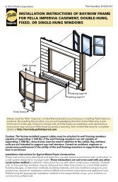
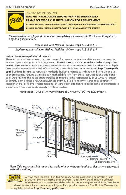
© 2011 <strong>Pella</strong> CorporationPart Number: 81DU0100INSTALLATION INSTRUCTION -NAIL FIN INSTALLATION BEFORE WEATHER BARRIER ANDFRAME SCREW OR CLIP INSTALLATION FOR REPLACEMENTALUMINUM-CLAD EXTERIOR HINGED PATIO DOORS (PELLA® PROLINE AND DESIGNER SERIES®)ALUMINUM-CLAD EXTERIOR ENTRY DOORS (PELLA® AND ARCHITECT SERIES®)Please read thoroughly and understand <strong>com</strong>pletely all the steps in this instruction prior tobeginning installation.Installation with Nail Fin follow steps 1, 2, 3, 4, 6, 7Replacement Installation Without Nail Fin follow steps 1, 2, 3, 5, 6, 7Instrucciones en español en el reverso.These instructions were developed and tested for use with typical wood frame wall constructionin a wall system designed to manage water. These instructions are not to be used with any otherconstruction method. Installation instructions for use with other construction methods or multipleunits may be obtained from <strong>Pella</strong> Corporation, a local <strong>Pella</strong> retailer or by visiting http://www.pella.<strong>com</strong>. Building designs, construction methods, building materials, and site conditions unique toyour project may require an installation method different from these instructions and additionalcare. Determining the appropriate installation method is the responsibility of you, your architector construction professional. Check with the individual (building owner, architect, contractor,installer and/or consumer) responsible for the project in addition to local building code officials todetermine if these products <strong>com</strong>ply with local codes.REMEMBER TO USE APPROPRIATE PERSONAL PROTECTIVE EQUIPMENT.FinCornerNailing Fin9"9" wide Flashing PaperSideFlashingTapeTopFlashingTapeAstragalSideFlashingTapeFlashingPaper9" Flashing Paper9"FlashingPaperSill SupportSill Flashing Tape #1Sill Flashing Tape #2Note: This instruction is intended for walls with or without sheathing. Illustrations show wallwithout sheathing.Always read the <strong>Pella</strong> ® Limited Warranty before purchasing or installing <strong>Pella</strong>products. By installing this product, you are acknowledging that this LimitedWarranty is part of the terms of the sale. Failure to <strong>com</strong>ply with all <strong>Pella</strong> installationand maintenance instructions may void your <strong>Pella</strong> product warranty. See Limited Warranty for<strong>com</strong>plete details at http://warranty.pella.<strong>com</strong>.
The performance of any building is dependent upon the design, installation, and workmanshiparchitect, contractor or structural engineer prior to installation of <strong>Pella</strong> products.The individual (building owner, architect, contractor, installer and/or consumer) responsible for theproject must take into account local conditions, building codes, inherent <strong>com</strong>ponent limitations,the effects of aging and weathering on building <strong>com</strong>ponents, and other design issues relevant toeach project.The determination of the suitability of all building <strong>com</strong>ponents for each project, as well as thedesign and installation of flashing and sealing systems, are the responsibility of the building owner,architect, contractor, installer and/or consumer.YOU WILL NEED TO SUPPLY:(Performance Upgrade & HurricaneShield) ® SmartFlash foil backed butyl window anddoor flashing tape or equivalent Window and Door Insulating FoamSealant by the Dow Chemical Company or equivalentlow pressure polyurethane window and doorInstallation Clip Option:TOOLS REQUIRED:and small flat blade)(Architect Series ® )(Designer Series ® )concrete applications1 ROUGH OPENING PREPARATION:A. Confirm the opening is plumb and level.Note: It is critical the bottom is level.
1 ROUGH OPENING PREPARATION (continued):B. Confirm the door will fit the opening.side, and in the center.Note: 1-1/2" or more of solid wood blocking isrequired around the perimeter of the opening.Fix any problems with the rough opening beforeproceeding.For Replacement Installation where nail fin is NOTbeing used, go to Step 5.Interior1BC. Apply flashing paper at the bottomrough opening. Position the top edge of the flashingpaper with the top of the sill plate. Center the flashingpaper with the opening width. Staple the flashing paperto the sill plate.Note: Sill flashing paper is not required for installationon concrete floors.D. Apply flashing paper to the sides of the roughopeninglonger than the height of the rough opening. Applyone piece to each jamb. Position the edge of theflashing paper with the inside edge of the trimmer (jackstud), and center the flashing paper with the height ofthe rough opening. Staple the flashing paper to thetrimmer.Exterior1D1CFOR DOORS USING OPTIONAL SILL PAN GO TO STEP 1I.E. Apply sill flashing tape #1.than the opening width. Apply at the bottom of the opening asNote: The tape is cut 12" longer than the width so that it willextend 6" up each side of the opening.F. Tab the sill flashing tape and fold.and press firmly to adhere it to the water resistive barrier. Apply sill flashing tape #2.In-swing doors: face of the framing.Note: The flashing tape may not fully cover the framing members.H. Attach the aluminum sill support or wood blocking to thePlace the sill support flush with the subfloor.GO TO STEP 2
1 ROUGH OPENING PREPARATION (continued):Optional Sill Pan Instructions:I. Cut the sill panNote: The 2" added onto the rough opening width is for a 1" bend on each end.J. Make a 1" cut in each fold at both end of the sill pan.Note: These cuts will allow the edges of the sill pan to be bent.Note: 4-5/8" wide for Out-Swing and In-Swing for 4-9/16" wall condition. For other wallconditions, measure wall depth and add 1/16".1"1JVariableINTERIOR SILL PAN LIP1"K. Cut 1" off each end of theinterior sill pan lip.1K1"EXTERIOR SILL PAN LIP 1"INTERIOR SILL PAN LIPEXTERIOR SILL PAN LIPL. Bend each end of the sill panupwards.1LINTERIOR SILL PAN LIPEXTERIOR SILL PAN LIP Install the sill pan by sliding intoplaceopening.N. Apply sill flashing tape. Cut athan the opening width. Applyat the bottom of the opening,shown.Note: If applicable, apply sprayadhesive to building felt prior toapplying the flashing tape.1MEXTERIOR SILL PAN LIPInstall flushagainst exteriorrough opening.1NEXTERIOR SILL PAN LIPFlashing TapeWeather BarrierExterior3"3"O. Cut two 9" pieces of flashing tape with acorners as shown.9"1O9"9"1-1/2"3"1-1/2"P. Apply the tabbed 9" pieces of flashingtap.cover the inside of the rough openingand lap over the side flange of the sillbottom flashing tape as shown.Q. Cut two 6" pieces of flashing tapeand apply to each side of the roughopening, overlapping the first pieceside flange of the sill pan as shown.9"1-1/2"1-1/2"1P1-1/2"TabsSideFlangeEXTERIOR SILL PAN LIPFlashing Tape9"1-1/2"1-1/2"1-1/2"Tabs1"1QEXTERIOR SILL PAN LIPFlashing Tape
EXTERIOR SILL PAN LIP1 ROUGH OPENING PREPARATION (continued):R. Cut a piece of flashing tape to the width of the opening. Install to the flanges of the sillflashing tape until the sill pan is covered to the interior sill pan lip.Note: The purpose of this tape is to seal the sill screws when installing the door.S. Cut two pieces of flashing tape 1-1/2" x 6"and apply to the bottom corners of the openingby beginning in the corner of the sill pan, withT. Attach the aluminum sill support or woodblockingsupport the edge of the door sill. Place the sillsupport flush with the subfloor.1SINTERIOR SILL PAN LIPEXTERIOR SILL PAN LIP1T 1PINTERIOR SILL PAN LIP1R1"2 PREPARE THE DOOR FOR INSTALLATION:TWO OR MORE PEOPLE WILL BE REQUIRED TO HANDLE THE PANEL AND FRAMESAFELY.A. Remove plastic wrap and cardboard packaging from door. Do not remove plasticshipping spacers. The shipping spacers will help keep the door square during installation.Do not open the door until it is fully fastened.Note: If grilles or hardware are removed from the door at this time, label them and storethem in a protected area.B. For doors without EnduraClad®Brickmould: Fold out installationremove or tear the fin corners.Note: If the fin corner is notat 90°, the door will not aligncorrectly on the interior.Note: The nail fin on doors withbrickmould and nail fin will<strong>com</strong>e from the factory folded up.Door withBrickmouldC. Doors using Installation Clips: Installinstallation clips. Place each clip sothe lip is facing up and against theinstallation fin at the locations shown inthe placement diagram. Secure each clipscrew through each of the outer twoholes of the three holes shown.Note: If clips are to be bent; pre-bendbefore attaching to frame.Note: Bending clips after attaching toframe will bow the frame.#6 x 5/8” corrosionresistant screwsLip2C6“ from end
EXTERIOR SILL PAN LIP3 SETTING AND FASTENING THE DOOR:A. Place three 3/8" beads of sealant.of the interior sill pan lip. This bead should also continue up the corner of the sill panbreak in the middle of the opening. Place a third sealant bead in the groove of the sill1/2"6"1st Bead2nd BeadINTERIOR SILL PAN LIP3ALeave a 2" breakin center of pan3216”3A3rd BeadTWO OR MORE PEOPLE WILL BE REQUIRED FOR THE FOLLOWING STEPS:Designer Series Doors:B. Cut and remove the strap that runs from the door lock to the sill of the door.Applications without sill panFor doors with no lock/bore:C. Remove the screws and blocking from the head and sill.Caution: The door panels will swing freely.D. Insert the door from the exterior of the building.DO NOT slide the bottom of the door into theopening. Sliding will damage the sealant lines.Place the bottom of the door at the bottomof the opening, then tilt the top into position.Center the door between the sides of theopening to allow clearance for shimming, andinsert one roofing nail in the first hole fromthe corner on each end of the top nailing fin.These are used to hold the door in place whileshimming it plumb and square.3DE. Plumb and square door. Place shims at eachhinge and lock strike location between thedoor and the sides of the opening. Keep shimsframe. Insert shims in other locations as neededsquare it in the opening. Check for frame twist;confirm consistent weatherstrip <strong>com</strong>pressionthe panels are even across the bottom.Note: On center latch double doors the lockstrike will not be shimmed since it is located inthe center of the unit. DO NOT over shim.3E
3 SETTING AND FASTENING THE DOOR (continued):F. Check the interior reveal. the measurement from the interior faceof the door to the interior face of thewall is equal at several points aroundthe door.Note: If dimensions are not equal,check to make sure the fins are foldedout to 90° at all points.3F 3Emm1INCHES2 320 30 40 50 60 70Interior3E 3D3E 3D3E 3FClip or Frame Screw Installation,go to Step 5I3E 3D Fasten the door punched hole in the nailing fin.Note: Make sure the fin corner is lying as flat as possible3GH. Carefully open the door(s) andremove all shipping spacers.Note: Be sure to remove thespacers from the bottom edgeof the door panel.Double Doors with Multipoint latch in center: Use the construction handle to operatethe active door handle. Operate the flushbolts per the instructions on the label onthe strike located on the astragal.I. Designer Series® Out-Swing: Install sill screws. Place a dab of sealant in eachre<strong>com</strong>mendations.All other: Sill screws are not needed.For <strong>com</strong>binations (Multi-wide): J. For Low Profile Sills: doors including a standard lock install tubs per instruction included with the sill strikepackage.Note: For concrete floors use masonry screws a minimum size of 3/16" diameter x 3"and pilot per manufacturer’s re<strong>com</strong>mendations for the screw.
3 SETTING AND FASTENING THE DOOR (continued):K. Double Doors Only:Designer Series®: Place a dab of sealant into the center sill3L 3KProLine®: Remove the screw from the sill strike located onthe door sill, then place a dab of sealant into the sill strikeEntry Doors: Remove the two screws from the sill strike3K 3Jlocated on the door sill. Place a dab of sealant into thescrews into the hole.L. Double Doors Only: Shim between the frame and the rough opening at the head strikethe door frame.Designer Series:hole.ProLine:Entry Doors: Remove the two screws from the head strike located on the door head. InstallNote: For doors with pre-drilled installation holes in the head. If installation holes arepresent, drill 1/8" diameter pilot hole into the rough opening and install a #8 x 3" corrosionresistant screw (provided) in each hole. the screw passes through the shims and into the structuralframing.N. Check door operation. Open and close the door to check forNote: If there are any problems with the operation, check toconfirm the door frame is installed plumb, level and square.If the reveal between the door panel(s) and frame is noteven, adjustments may be made:Doors without adjustable hinges: Plastic shims locatedbehind the hinges may be removed to adjust the revealbetween the door panel and door frame. Additional hingeshims may be added if required.Note: Doors with adjustable hinges will have a (+)(-) on thedoor panel hinge leaf to indicate possible adjustments anddoors without adjustable hinges do not have adjustmentindicators.Adjustable hinges are not designed to make up for incorrectinstallation of a door frame. Before adjusting hinges, confirmthe door is installed plumb, level and square.AdjustableHingeInteriorNon-AdjustableHingeO. For Doors with adjustable hinges: The hinges can be used to move the panel side to sideby moving all hinges in the same direction or the hinges can slightly rotate the panel byAllen wrench for Designer Series doors to turn the center screw clockwise (+) to increase thespace between the hinge side of the frame and door panel. Turn the center screws counterclockwise(-) to decrease the space between the hinge side of the frame and the door panel.Note: Do not adjust the hinge with the top and bottom screws loose; this could force thehinge to adjust beyond its design capability which can cause the hinge to bind, damagethe hinge and/or pull out the screws. A 3/4 turn of the center screw provides approximately5/32" adjustment.3M3LInterior
3 SETTING AND FASTENING THE DOOR (continued):P. Doors with a lock strike in the side (jamb) and without a sidelight on the lock side:holes located in the frame as follows:Door Frame Corner:Drill pilot holes through the pre-drilled hole located in the upper frame corner on the lockDoors with Multi-point Lock:Drill through the one pre-drilled hole located in each lock strike. (Pull back frameweatherstrip to locate open hole in strike).Center Latch and Deadbolt Lock:making sure it passes through the shim and into the rough opening.Note: This step does not apply to center latching double doors.3P1 3OJambHead~ 8”3P23P2Pull back weatherstrip to expose strike hole.3P33O4INTEGRATINGTHE DOOR TO THEWATER RESISTIVE BARRIER:Note: The flashing tape must be appliedapproximately 1/2" onto the frame cladding at thejambs and head. Pre-folding the tape at 1/2" beforeremoving the paper backing will make it easier toapply the tape correctly. If the siding is less than 1/2"thick, adjust the dimension of the fold so the exteriorsealant line will cover the exterior edge of the tape.FlashingTapeA. Apply side flashing tape. Cut two pieces of flashingthe nailing fin and onto the water resistive barrier onPress the tape down firmly while folding down the4A
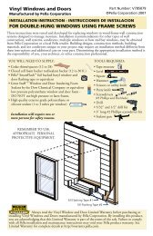
4INTEGRATINGTHE DOOR TO THEWATER RESISTIVE BARRIER (continued):B. Apply top flashing tape. Cut a piece of flashingtape long enough to go across the top of the doorcladding, over the top nailing fin as shown. Foldthe overlapping tape down, and press all tapedown firmly.Note: The top flashing tape must overlap the sideflashing tape to prevent water from getting behind it.4B C. Apply the top flashing paper. Cut one piece ofthe rough opening. Position the bottom edge of theflashing paper flush with the frame of the door andcenter the flashing paper with the door. Staple theflashing paper to the header.Note: When applying the first layer of building felt,ensure the sill flashing paper overlaps the buildingfelt. This will tie the door system into the buildingwater management system.4C 5DOORAs required by local code (such as Florida product approval system), additional anchorsmay be required. Install them at this time.REPLACEMENT IN SIDINGWITHOUT NAIL FIN:Head Flashing Instruction and Rough Opening PreparationNote: <strong>Pella</strong> Re<strong>com</strong>mends and some codes require the use of a head drip flashing. If thereis a functioning, existing flashing, proceed to step 5D.A. Prepare the head flashing by cutting it the same widthas the j-channel/siding opening.B. Pry the top (head) j-channel/siding away from thesheathing enough so the head flashing can be slidunder the house wrap.C. Insert the head flashing behind the j-channel/siding and behind the house wrap (if present).HOUSE WRAPSIDINGJ-CHANNELFLASHING TAPEHEAD FLASHING
5DOORREPLACEMENT IN SIDINGWITHOUT NAIL FIN (continued):D. Clean the vinyl j-channel/trim and rough opening with isopropyl alcohol orwindow cleaner to make sure it is free of dirt and debris before proceeding.E. Place a 3/8" bead of sealant (or enough to coverthe area) between the j-channel and the roughopening at the head and jambs only. Tool thesealant with a putty knife to press the sealant intothe opening.CAUTION: The cut fin may have sharp edges!HEADANDJAMBSONLY5E 2BF. Place a 3/8" bead of sealant at each corner ofthe opening.PRESSSEALANTINTOOPENING2C5F Starting at the top (head) of the opening, cutwidth of the rough opening. Place the flashingtape onto the j-channel edge, over the sealantFor Sill Preparation see steps 1E - 1T.5G H. Cut two pieces of flashingtape 6" longer than the heightof the opening. On one side(jamb) of the opening, start thetape in the upper corner andwork down and onto the sill.from the j-channel edge overthe sealant and onto the roughopening surface.5HSee steps 3A - 3F only for Setting the Door.
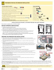
5DOORREPLACEMENT IN SIDINGWITHOUT NAIL FIN (continued):Fastening Door to OpeningI. After setting the door plumb level & square, secure the door to the opening. If usingframe screw method then have two people hold the door upright and secure while acorner, then open the other panel and repeat on the opposite jamb. See below for pilotALTERNATE ANCHORING METHODS, CLIP AND SCREW PLACEMENT:DOUBLE OPERABLESINGLE FIXED OR OPERABLE3P 5I3P 5I3" 3"6"6"6" 16" MAX 6"16" MAXO.C.O.C.6"6"6"6" 16" MAX 6"O.C.6"6"6" 16" MAX 6"O.C.6"6"6"3P 5I3P 5I3P 5I16"MAX.O.C.16"MAX.O.C.16"MAX.O.C.16"MAX.O.C.16"MAX.O.C.16"MAX.O.C.6"6" 16" MAX 6" 16" MAX 6"O.C. 6" O.C.3P 5I6"6"6" 16" MAX 6"O.C.6"6"6" 16" MAX 6"O.C.6"3" 3"6"6"Vent PlacementFixed PlacementVent PlacementFixed PlacementFixed and VentPlacementFixed PlacementVent PlacementOut-Swing Screw LocationsIn-Swing Screw Locations
5DOOR REPLACEMENT IN SIDINGWITHOUT NAIL FIN (continued):Frame Screw Method:Note: If installing with installation clips, proceed to step P.J. Jambsand not into the rough opening at the locations shown on the diagrams.Note: Out-Swing Doors Only - If choosing to locate clearanceholes through the frame to be concealed by door panel; removeframe weatherstrip and drill holes under the weatherstrip.5JK. Frame Headframe head only and not into the rough opening at the locations shown on the diagrams.L. Thresholdbut not into the rough opening at the locations shown on the diagrams Drill 1/8" x 1" deep pilot holes through the clearance holes and into the rough openingframing in the head, jambs and threshold of the unit frame.N. Secure the jambs and head of the door.screws through the door frame and shim, into the rough framing. Drive the screws untilsnug but DO NOT over-tighten the screws. DO NOT bend or bow the unit frame.O. Secure the sillGo back to 3H - 3P to <strong>com</strong>plete fastening through hinges and strikes.Installation Clip Method:See Step 2C for Clip Application DetailsP. Fasten the door to the opening by drivinginto the pre-punched holes in the clips.If the clips are bent and fastened to theinterior stud/block, install the screws asclose to the bend as possible.Note: DO NOT shim above the door. Formasonry openings use two masonry screwsthat are a minimum size of 3/16" x 1-1/2"per clip. Pre-drill the masonry per screwmanufacturer’s re<strong>com</strong>mendations beforeattempting to drive the screws in.5F 5PGo back to 3H - 3P to <strong>com</strong>plete fastening through hinges and strikes.
6 INTERIOR SEAL:Caution: Ensure use of low pressure polyurethane window and door insulating foamsand strictly follow the foam manufacturer’s re<strong>com</strong>mendations for application. Use ofhigh pressure foams or improper application of the foam may cause the door frame tobow and hinder operation.A. Add a sealant bead across the inner sill and 6" upeach jamb between the frame and rough opening.InteriorB. Apply insulating foam sealant. From the interior,between the door and the rough openingsurface of the shims to create a continuous seal.Follow foam manufacturer's instructions.Note: DO NOT place any foam between jambextensions and the rough opening.6"6C 6A6A 6BC. Check the door operation by opening andclosing the door.Note: If the door does not operate correctly,check to make sure it is still plumb, level, squareand that the sides are not bowed. If adjustmentsare required, remove the foam with a serratedknife. Adjust the shims, and reapply the insulatingfoam sealant.
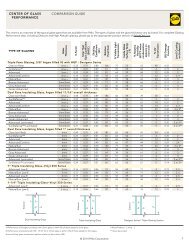
7SEALINGTHE DOOR TO THEEXTERIOR WALL CLADDING:When applying siding, brick veneer or other exterior finish material, leave adequate spacebetween the door frame and the material for sealant. Refer to the illustration corresponding toyour finish material.Note: The sealant details shown are standard re<strong>com</strong>mendations from the sealant industry.Contact your sealant supplier for re<strong>com</strong>mendations and instructions for these and any otherapplications.InsulatingFoamBRICKVENEER3/8"Backer Rodand Sealanttypical3/8"ClearanceAccessoryGroovePerimeter Sealantmust extend toroom side ofAccessory Groove.InsulatingFoamVINYL/STEELSIDING3/8"Backer Rodand Sealanttypical3/8"ClearanceAccessoryGroovePerimeter Sealantmust extend toroom side ofAccessory Groove.InsulatingFoamSOUTHWESTERNWALLWITHSTUCCO3/8"Backer Rodand Sealanttypical3/8"ClearanceAccessoryGroovePerimeter Sealantmust extend toroom side ofAccessory Groove.3/8"Min.3/8"Min.3/8"Min.InsulatingFoamWOODSIDINGWITHTRIM3/8"Backer Rodand Sealanttypical3/8"ClearanceAccessoryGroovePerimeter Sealantmust extend toroom side ofAccessory Groove.InsulatingFoamSTUCCO3/8"Backer Rod andSealant typical3/8" ClearanceAccessoryGroovePerimeter Sealantmust extend toroomside ofAccessory Groove.3/8"Min.3/8"Min.Replacement Frame:Note: When applying siding, brick veneer or other exterior finish materials, leave adequatespace between the door frame and the material for sealant. Refer to the illustrationcorresponding to your finish material. Not allowing adequate space or not using backer rodmay cause the sealant to break down prematurely and allow water to infiltrate.InsulatingFoamBRICK VENEERBacker rodandsealant typicalInsulatingFoamWOOD SIDINGWITH TRIMBacker rodandsealant typical3/8"3/8"3/8"Min.
7SEALINGTHE DOOR TO THEEXTERIOR WALL CLADDING (continued)A. Insert backer rod into the space around theclearance between the backer rod and theNote: Backer rod adds shape and depth forthe sealant line.B. Apply a bead of high quality exterior gradesealant to the entire perimeter of the door.C. Shape, tool and clean excess sealant. Whenfinished, the sealant should be the shape ofan hourglass.7A7BD. Remove plastic guards at the base of thedoor once construction is <strong>com</strong>plete.E. Install the hardware. Refer to the instructions
INTERIOR FINISHINGIf products cannot be finished immediately, cover with clear plastic to protect from dirt, damageand moisture. Remove any construction residue before finishing. Sand all wood surfaces lightly<strong>Pella</strong> products must be finished per the below instructions; failure to follow these instructions voidsthe Limited Warranty.FINISHING INSTRUCTIONSPaint or finish immediately after installation.Note: DO NOT paint, stain or finish weatherstrip or vinyl parts! If paint, stain or finish gets on theweatherstripping, wipe it off immediately with a damp cloth. To maintain proper performance, donot remove weatherstrip, foam corner seal wedges or gaskets. Air and water leakage may resultif these factory-installed items are removed. After finishing, allow doors to dry <strong>com</strong>pletely beforeclosing them. <strong>Pella</strong> will not be responsible for finishing imperfections. The use of unapprovedfinishes, solvents or cleaning chemicals may cause adverse reactions with door materials. <strong>Pella</strong> willnot be responsible for problems caused by the use fo unapproved materials. If in doubt, contactyour local retailer or representative.Use of inappropriate finishes, solvents, brickwash or cleaning chemicals will cause adverse actionswith window and door materials and voids the Limited Warranty.owner's manual by contacting your local <strong>Pella</strong> retailer. This information is also available on www.pella.<strong>com</strong>.Factory Prefinished Panels: A door panel that has been prefinished with stain or paint from thefactory requires no additional finishing. Clean the surface with mild soap and water. DO NOT useabrasives. DO NOT scrape or use tools that might damage the surface.Clad Exterior Frame:EnduraClad® baked-on-factory finish that needs no painting. Clean this surface with mild soap andwater. DO NOT use abrasives. DO NOT scrape or use tools that might damage the surface.Panel Cleaning and Prep Instructions for Unfinished or Primed Panels: Dry wipe dust fromconstruction. To remove smudges, lightly wipe surface with warm water. DO NOT sand surface ofsurface with mineral spirits for fiberglass panels and warm water for steel panels. Let door andsidelight surfaces dry <strong>com</strong>pletely before applying finish. Finish the door panels as soon as possibleafter installation.Staining fiberglass panels or unfinished interior frame members: Fiberglass door and sidelightpanels may be stained with a gel stain if a wood look is desired. <strong>Pella</strong> offers stain kits in a varietymay be stained with wood stains and should be finished with a minimum of two coats of a clearand the door panel.Note: The fiberglass base color tone will vary. This variance is normal and will not impact the staincolor of the door.Painting Instructions:that has a good blocking resistance. On units with glass, do not bridge paint between the outerFailure to use the correct type of finish may result in a door that sticks shut. Ask a qualified paintprofessional to specify a product with good blocking resistance.On patio doors:
TROUBLESHOOTING - Adjustable Strike Latching IssuesIssue 1:Door is difficultto latch. Removethe strike andadjustablestrike shim thenreinstall thestrike.Issue 2:Door needs to closemore tightly againstthe weather-strip.Remove the strikeand adjustablestrike shim. Removethe tabs from theadjustable strikeshim and installso that the thickerside is visible atthe strike edge.Reinstall the strike.