combination fire / smoke dampers installation instructions - NCA ...
combination fire / smoke dampers installation instructions - NCA ...
combination fire / smoke dampers installation instructions - NCA ...

You also want an ePaper? Increase the reach of your titles
YUMPU automatically turns print PDFs into web optimized ePapers that Google loves.
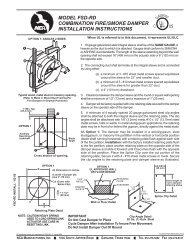
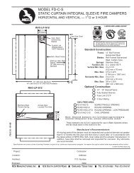
COMBINATION FIRE / SMOKE DAMPERS<br />
INSTALLATION INSTRUCTIONS<br />
C<br />
CLASSIFIED<br />
U L R<br />
US<br />
FSDGENINSTALL - 02-05 (INSTALLATIONFSD)<br />
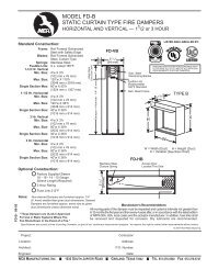
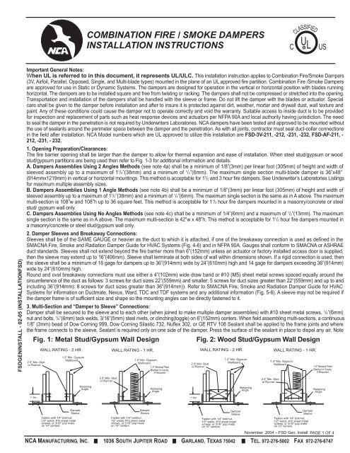
Important General Notes:<br />
When UL is referred to in this document, it represents UL/ULC. This <strong>installation</strong> instruction applies to Combination Fire/Smoke Dampers<br />
(3V, Airfoil, Parallel, Opposed, Single, and Multi-blade types) mounted in the plane of an UL approved <strong>fire</strong> partition. Combination Fire /Smoke Dampers<br />
are approved for use in Static or Dynamic Systems. The <strong>dampers</strong> are designed for operation in the vertical or horizontal position with blades running<br />
horizontal. The <strong>dampers</strong> are to be installed square and free from twisting or racking. The <strong>dampers</strong> shall not be compressed or stretched into the opening.<br />
Transportation and <strong>installation</strong> of the <strong>dampers</strong> shall be handled with the sleeve or frame. Do not lift the damper with the blades or actuator. Special<br />
care shall be given to the damper before <strong>installation</strong> and after to insure it is protected against dirt, weather, mortar and drywall dust, wall texture and<br />
paint. Any of these conditions could cause the damper not to operate correctly and void the warranty. Suitable access to inside duct is to be provided<br />
for inspection and replacement of parts such as heat response devices and actuators per NFPA 90A and local authority having jurisdiction. The need<br />
to seal the damper in the penetration is not required by Underwriters Laboratories. <strong>NCA</strong> <strong>dampers</strong> have been tested and approved to be mounted without<br />
the use of sealants around the perimeter space between the damper and the penetration. As with all joints, contractor must seal duct-collar connections<br />
in the field after <strong>installation</strong>. <strong>NCA</strong> Model numbers which are UL approved to utilize this <strong>installation</strong> are FSD-3V-211, -212, -231, -232, FSD-AF-211, -<br />
212, -231, - 232.<br />
1. Opening Preparation/Clearances:<br />
The <strong>fire</strong> barrier opening shall be larger than the damper to allow for thermal expansion and ease of <strong>installation</strong>. When steel stud/gypsum or wood<br />
stud/gypsum partitions are being used then refer to Fig. 1-3 for additional information and details.<br />
A. Dampers Assemblies Using 2 Angles Methods (see note 4a) shall be a minimum of 1/8”(3mm) per linear foot (305mm) of height and width of<br />
sleeved assembly up to a maximum of 1 1 /2”(38mm) and a minimum of 1 /4”(6mm). The maximum single section multi-blade damper is 36”x48”<br />
(914mmx1219mm) in vertical or horizontal mountings. This method is acceptable for 1 1 /2 and 3 hour <strong>fire</strong> <strong>dampers</strong>. See Underwriter’s Laboratories Listings<br />
for maximum multiple assembly sizes.<br />
B. Dampers Assemblies Using 1 Angle Methods (see note 4b) shall be a minimum of 1/8”(3mm) per linear foot (305mm) of height and width of<br />
sleeved assembly up to a maximum of 1 1 /2”(38mm) and a minimum of 1 /4”(6mm). The maximum single section is the same as in A above. The maximum<br />
multi-section is 108”w and 108”h up to 36 square feet. This method is acceptable for 1 1 /2 hour <strong>fire</strong> <strong>dampers</strong> mounted in a masonry/concrete or steel<br />
stud/ gypsum wall only.<br />
C. Dampers Assemblies Using No Angles Methods (see note 4c) shall be a minimum of 1/4”(6mm) and a maximum of 1 /2”(13mm). The maximum<br />
single section is the same as in A above. The maximum multi-section is 42”w x 48”h. This method is acceptable for 1 1 /2 hour <strong>fire</strong> <strong>dampers</strong> mounted in<br />
a masonry/concrete or steel stud/gypsum wall only.<br />
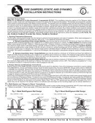
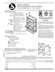
2. Damper Sleeves and Breakaway Connections:<br />
Sleeves shall be of the SAME GAUGE or heavier as the duct to which it is attached, if one of the breakaway connection is used as defined in the<br />
SMACNA Fire, Smoke and Radiation Damper Guide for HVAC Systems (Fig. 4-6) and in NFPA 90A. Gauges shall conform to SMACNA or ASHRAE<br />
duct standards. Sleeves shall not extend beyond the <strong>fire</strong> barrier more than 6”(152mm) unless an actuator or factory installed access door is supplied,<br />
then the sleeve may extend up to 16”(406mm). Sleeve shall terminate at both sides of wall within dimensions shown. If a rigid connection is used, then<br />
the sleeve shall be a minimum of 16 gage for <strong>dampers</strong> up to 36”(914mm) wide by 24”(610mm) high and 14 gage for <strong>dampers</strong> exceeding 36”(914mm)<br />
wide by 24”(610mm) high.<br />
Round and oval breakaway connections must use either a 4”(102mm) wide draw band or #10 (M5) sheet metal screws spaced equally around the<br />
circumference of the duct as follows: 3 screws for duct sizes 22”(559mm) and smaller; 5 screws for duct sizes greater than 22”(559mm) and up to and<br />
including 36”(914mm): 8 screws for duct sizes greater than 36”(914mm)). Refer to SMACNA Fire, Smoke and Radiation Damper Guide for HVAC<br />
Systems for information on Ductmate, Nexus, Ward, TDC and TDF systems and any additional information (Fig. 5-6). A sleeve may not be required if<br />
the damper frame is of sufficient size and shape so the mounting angles can be directly fastened to it.<br />
3. Multi-Section and “Damper to Sleeve” Connections:<br />
Damper shall be secured to the sleeve and to each other (when joined to make multiple damper assemblies) with #10 sheet metal screws, 1 /4”(6mm)<br />
nut and bolts, 1 /4”(6mm) tack welds, 3/16”(5mm) steel rivets, or clinching(toggle) on 6”(152mm) centers. When field assembling multi-sections, a continuous<br />
1/8” (3mm) bead of Dow Corning 999, Dow Corning Silastic 732, Nuflex 302, or GE RTV 108 Sealant shall be applied to the frame joints and where<br />
the frame connects to the sleeve. Sealant is required only on one side of the damper. Press the surface of the sealant in place to dispel any air. Note<br />
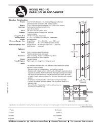
Fig. 1: Metal Stud/Gypsum Wall Design Fig. 2: Wood Stud/Gypsum Wall Design<br />
2.5" Min. Stud<br />
or Runner<br />
WALL RATING - 2 HR.<br />
1.2" Min. Gypsum<br />
Wallboard<br />
Retaining<br />
Angle<br />
2.5" Min. Stud<br />
or Runner<br />
WALL RATING - 1 HR.<br />
1.2" Min. Gypsum<br />
Wallboard<br />
1.5" Mineral Fiber<br />
Blanket in Cavity,<br />
If Required<br />
Retaining<br />
Angle<br />
2.5" Min. Stud<br />
or Runner<br />
WALL RATING - 2 HR.<br />
1.2" Min. Gypsum<br />
Wallboard<br />
Retaining<br />
Angle<br />
2.5" Min. Stud<br />
or Runner<br />
WALL RATING - 1 HR.<br />
1.2" Min. Gypsum<br />
Wallboard<br />
1.5" Mineral Fiber<br />
Blanket in Cavity,<br />
If Required<br />
Retaining<br />
Angle<br />
1" Min.<br />
1" Min.<br />
Damper<br />
Sleeve<br />
Fasten with 1/4" bolt/nut,<br />
1/2" welds, #10 sheet metal<br />
screws, or 3/16" pop rivets<br />
on 10" centers.<br />
Damper<br />
Sleeve<br />
Fasten with 1/4" bolt/nut,<br />
1/2" welds, #10 sheet metal<br />
screws, or 3/16" pop rivets<br />
on 10" centers.<br />
Damper<br />
Sleeve<br />
Fasten with 1/4" bolt/nut,<br />
1/2" welds, #10 sheet metal<br />
screws, or 3/16" pop rivets<br />
on 10" centers.<br />
Damper<br />
Sleeve<br />
Fasten with 1/4" bolt/nut,<br />
1/2" welds, #10 sheet metal<br />
screws, or 3/16" pop rivets<br />
on 10" centers.<br />
November 2004 – FSD Gen. Install PAGE 1 OF 4<br />
<strong>NCA</strong> MANUFACTURING, INC. 1036 SOUTH JUPITER ROAD GARLAND, TEXAS 75042 TEL. 972-276-5002 FAX 972-276-6747
Note: Gypsum panels screwed to all studs and<br />
runner flanges, 12” oc maximum<br />
surrounding opening. All fasteners are<br />
to be UL approved per UL design.<br />
4. Methods of Securing<br />
Damper in Opening:<br />
Screws<br />
Section A-A<br />
a. Two Angle (Two Sided) Method: This method is<br />
the oldest and most commonly used. This method is<br />
approved for use in UL approved concrete/masonry<br />
partitions, steel stud/gypsum walls, and wood<br />
stud/gypsum walls. In this method 2 sets of angles are<br />
used to secure the damper in the opening, one on each<br />
side of the partition (See Fig. 7). Two Angle Method is<br />
approved for 1 1 /2 and 3 hour <strong>dampers</strong>, vertical or<br />
horizontal orientation, and any maximum size multisection<br />
UL approved damper (see Underwriter’s<br />
Laboratories Listings for maximum assembly sizes).<br />
Angles shall be a minimum of 1 1 /2” x 1 1 /2” (37mmx37mm)<br />
x 16 gauge. Angles are to be fastened to the sleeve on<br />
6” centers with #10 (M5) sheet metal screws, 3/16”<br />
2.5" Min. Stud<br />
2.5" Min. Runner<br />
A<br />
Runner<br />
90 Bend<br />
Double Stud Not<br />
Required on Penetrations<br />
36" x 36"<br />
Or Smaller<br />
2 Panhead<br />
Screws<br />
24" O.C.<br />
Max.<br />
Fig. 3: Metal or Wood Stud Wall<br />
16" 16"<br />
A<br />
See UL Directory for<br />
Maximum Allowable<br />
Opening Size Per<br />
Fire Damper Model<br />
Width<br />
Height<br />
12"<br />
2"<br />
2"<br />
Ceiling Runner<br />
Floor<br />
Runner<br />
(5mm) steel pop rivets, 1 /2” (13mm) tack welds, or 1 /4”<br />
(6mm) diameter nut and bolts with not more than 2” (51mm) from each end with a minimum of two connections per side/leg. The<br />
angles are to overlap the partition a minimum of 1”(25mm). These angles may be of a unit type construction and may or may not be<br />
fastened to each other at the corners. When the duct work terminates at the damper or <strong>installation</strong> prohibits angles from turning<br />
out/away from the wall, the retaining angle shall be reversed (leg turned into the opening) providing the size of the opening is increased<br />
by an amount equal to twice the combined thickness of the angle and the height of the screw or bolt head to maintain expansion<br />
clearances. See note 1A for information on clearances. See Fig. 7 for detailed drawings of <strong>installation</strong>s.<br />
FSDGENINSTALL - 02-05 (INSTALLATIONFSD)<br />
b. One Angle (Single Sided) Method: In this method 1 set of angles are used to secure the damper in the opening. This method is<br />
approved for use in UL approved concrete/masonry partitions and steel stud/gypsum walls. Only one side of the <strong>fire</strong> partition will have<br />
the angles installed (see Fig. 8). One Angle Method is approved for 1 1 /2 hour <strong>dampers</strong> only, vertical and horizontal (angles on top side<br />
only) orientations, and the maximum size shall be 108” wide or 108” high up to 36 square feet and up to the maximum multi-section<br />
UL approved damper size (see Underwriter’s Laboratories Listings for maximum assembly sizes). Angle shall be a minimum of 1 1 /2”<br />
x 1 1 /2” (37mmx37mm) by 16 gauge. Angles are to be fastened to the sleeve on 6” centers with #10 (M5) sheet metal screws, 3/16”<br />
(5mm) steel pop rivets, 1 /2” (13mm) tack welds, or 1 /4” (6mm) diameter nut and bolts with not more than 2” (51mm) from each end with<br />
a minimum of two connections on each side/leg top and bottom. The angles are also to be fastened to the <strong>fire</strong> partition with: in<br />
concrete/masonry partitions with #10 (M5) self-tapping concrete anchors or concrete screws on 6” (152mm) centers and must<br />
engage the <strong>fire</strong> partition a minimum of 1 1 /2” (38mm); in steel stud/gypsum partitions secure the angles to the partition with #10 (M5)<br />
screws long enough to penetrate the J-Runners and E-Stud by a minimum of 3/8” (10mm). Use a minimum of two fasteners per side.<br />
The angles are to overlap the partition a minimum of 1” (25mm). These angles may be of a unit type construction and may or may<br />
not be fastened to each other at the corners. When the duct work terminates at the damper or <strong>installation</strong> prohibits angles from turning<br />
out/away from the wall, the retaining angle shall be reversed (leg turned into the opening) providing the size of the opening is increased<br />
by an amount equal to twice the combined thickness of the angle and the height of the screw or bolt head to maintain expansion<br />
clearances. Angles can be placed in front of or behind the drywall attaching directly to the steel studs or masonry. <strong>NCA</strong>’s Frame<br />
Retaining Angles (FRA) can be used in place of the angle mentioned above. See note 1B for information on clearances. See Fig. 8<br />
for detailed drawings of <strong>installation</strong>s.<br />
c. No Angle Method: In this method No angles are used to secure the damper in the opening. This method is approved for use in<br />
UL approved concrete/masonry partitions and steel stud/gypsum walls. This method uses a minimum 3 /4” (19mm) flange is on one<br />
end of the sleeve. The damper/sleeve assembly is placed in the opening so that the flange rest flush up to the partition, then the<br />
fasteners are placed through the sleeve into the partition (see Fig. 9). No Angle Method is approved for 1 1 /2 hour <strong>dampers</strong> only, vertical<br />
and horizontal (flange on top side only) orientations, and the maximum size shall be 42” (1067mm) wide by 48” (1219mm) high up to<br />
the maximum multi-section UL approved damper size (see Underwriter’s Laboratories Listings for maximum assembly sizes). The<br />
sleeve flange shall be a minimum of 3 /4” (19mm) high by 20 gauge steel. If a flange/angle is added, it shall be a minimum of 1” x 1”<br />
(25mm x 25mm) by 18 gauge steel and fastened with #10 (M5) bolts or screws, 1 /2” (13mm) welds, or 3/16” (5mm) rivets to the sleeve,<br />
at a maximum spacing of 6” (152mm) o.c., not more than 2” (51mm) from each end with a minimum of two fasteners per side. The<br />
sleeve is to be fastened to the <strong>fire</strong> partition with: in concrete/masonry partitions with #10 self-tapping concrete anchors or concrete<br />
screws on 6” (152mm) centers and must engage the <strong>fire</strong> partition a minimum of 1 1 /2” 38mm); in steel stud/gypsum partitions secure<br />
the angles to the partition with #10 (M5) screws long enough to penetrate the J-Runners and E-Stud by a minimum of 3/8” (10mm).<br />
Use a minimum of two fasteners per side. The sleeve flange can be placed in front of or behind the drywall attaching directly to the<br />
steel studs or masonry. Be sure to not stretch the damper when securing it into the partition. Stretching the damper can cause it to<br />
bind up and prevent it from operating properly. <strong>NCA</strong>’s Frame Retaining Angles (FRA) can be used in place of the angle mentioned<br />
above. See note 1C for information on clearances. See Fig. 9 for detailed drawings of <strong>installation</strong>s.<br />
November 2004 – FSD Gen. Install<br />
PAGE 2 OF 4<br />
<strong>NCA</strong> MANUFACTURING, INC. 1036 SOUTH JUPITER ROAD GARLAND, TEXAS 75042 TEL. 972-276-5002 FAX 972-276-6747
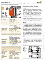
5. Actuator Connections:<br />
Electrical and/or pneumatic connections to damper actuators should be made in accordance with wiring and piping diagrams developed<br />
in compliance with applicable codes, ordinances and regulations. Be sure to check actuator for proper voltage and current draw.<br />
Tampering with the actuator’s <strong>installation</strong> or connecting the actuator to an improper voltage and current may void the warranty.<br />
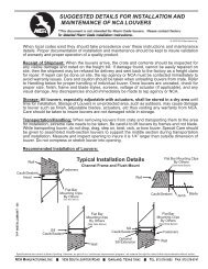
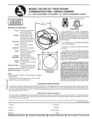
BREAKAWAY CONNECTIONS<br />
Traditional Breakaway Style Transverse Joints<br />
Transverse joints illustrated at right have always been<br />
approved as breakaway connections. SMACNA testing<br />
has also approved the following variations as breakaway<br />
connections.<br />
• Standing "S' joints can be applied with no. 10<br />
sheetmetal screws (through joint and duct) subject to<br />
the following limitations: Maximum 2 screws in each<br />
side and in bottom joint.<br />
• Transverse joints illustrated can<br />
be applied as top and bottom<br />
joints with Drive Slip - side joints<br />
in duct heights up to 20 inches.<br />
(508 mm)<br />
Drive Slip Joint<br />
Round and Oval Duct Breakaway Connections<br />
Fig. 4<br />
Plain "S" Slip Hemmed "S" Slip Double "S" Slip<br />
Inside Slip Joint Standing "S" Standing "S" (Alt.)<br />
Standing "S" (Alt.)<br />
Standing "S"<br />
(Bar Reinforced)<br />
Standing "S"<br />
(Angle Reinforced)<br />
FSDGENINSTALL - 02-05 (INSTALLATIONFSD)<br />
Round or flat oval ducts connected to Type R, CR or CO damper collars may use no. 10 sheetmetal screws as follows:<br />
• Ducts to 22" (558 mm) wide (or dia.) and smaller may use 3 screws.<br />
• Ducts larger than 22" (558 mm) wide (or dia.) and up to 36" (914 mm) dia. may use 5 screws.<br />
• Ducts larger than 36" (914 mm) wide (or dia.) may use 8 screws.<br />
NOTE: All breakaway connections described may have duct sealant applied in accordance with SMACNA reccomendations.<br />
Manufactured Flanged System<br />
Breakway Connections<br />
Flanged connection systems manufactured by Ductmate,<br />
Ward, and Nexus are approved as breakaway<br />
connections<br />
when installed as illustrated.<br />
Proprietary Flange System<br />
Breakaway Connections<br />
TDC and TDF systems are approved<br />
as breakaway connections when<br />
installed as described in the TDC or<br />
TDF addendum to the SMACNA Duct<br />
Construction Standards except the<br />
corners may not be bolted.<br />
Standard 6" (152 mm) metal clip may<br />
be used with spacing as shown<br />
in diagram.<br />
Sleeve<br />
Fig. 6<br />
Typical TDC/TDF Joint<br />
(Attach per<br />
manufacturers'<br />
<strong>instructions</strong>)<br />
Duct<br />
Duct<br />
6" long 1/16" max.<br />
thickness plastic<br />
cleats 12" c-c (min.<br />
1 per side)<br />
Flanged system<br />
angles<br />
60" Duct<br />
4 Reqd.<br />
Clip Spacing<br />
48" Duct<br />
3 Reqd.<br />
6"<br />
36" Duct<br />
3 Reqd.<br />
24" Duct<br />
2 Reqd.<br />
7"<br />
5"<br />
18" Duct &<br />
Smaller<br />
1 Reqd.<br />
5"<br />
Fig. 5<br />
Std. Clip<br />
Length<br />
6"<br />
Neoprene Gasket<br />
between all angles<br />
CL<br />
Duct<br />
© 2004 <strong>NCA</strong> Manufacturing<br />
Fire Damper Sleeve<br />
Do not bolt corners<br />
9"<br />
5"<br />
5"<br />
7"<br />
6"<br />
PAGE 3 OF 4<br />
<strong>NCA</strong> MANUFACTURING, INC. 1036 SOUTH JUPITER ROAD GARLAND, TEXAS 75042 TEL. 972-276-5002 FAX 972-276-6747
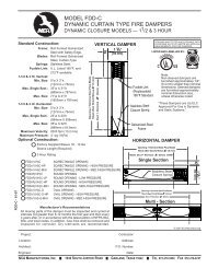
Fig. 7 – Two Angle (Two Sided) Method<br />
Retaining<br />
Angle<br />
Fire Wall<br />
Steel/Wood/Gypsum or<br />
Masonry<br />
As Found in the UL File<br />
Standard Turned Out Angles<br />
Fire Rated Partition<br />
Typ.<br />
Sides<br />
3.5<br />
Fire/Smoke<br />
Damper<br />
Sleeve<br />
Retaining<br />
Angle<br />
Fasteners<br />
Sleeve<br />
2"<br />
Actuator<br />
Fire Rated Partition<br />
Damper<br />
Sleeve<br />
Fasteners<br />
Fasteners<br />
Combination Fire and Smoke Damper<br />
Retaining<br />
Angle<br />
Sleeve<br />
Retaining Angle<br />
Min. 1" Overlap<br />
Actuator<br />
Damper<br />
Retaining<br />
Angle<br />
Fire Wall<br />
Steel/Gypsum or Masonry<br />
As Found in the UL File<br />
Resistance Directory<br />
Fig. 8 -- One Angle (Single Sided) Method<br />
Fire/Smoke<br />
Damper<br />
Sleeve<br />
Steel/Gypsum<br />
Wall<br />
Steel/Gypsum<br />
Wall<br />
Masonry Wall<br />
UL Approved<br />
Wall Design<br />
Actuator<br />
Retaining<br />
Angle<br />
Fasteners<br />
UL Approved<br />
Wall Design<br />
Sleeve<br />
Fasteners<br />
Retaining<br />
Angle<br />
UL Approved<br />
Wall Design<br />
Sleeve<br />
Retaining<br />
Angle<br />
Fasteners<br />
Sleeve<br />
FSDGENINSTALL - 02-05 (INSTALLATIONFSD)<br />
Grille<br />
Grille Mount<br />
UL Approved<br />
Wall Design<br />
Actuator<br />
Fire/Smoke<br />
Damper<br />
Sleeve<br />
Gypsum<br />
3/4" Flange<br />
(Typ. 4<br />
20 Ga. St.<br />
Damper<br />
#10 Sheet Metal<br />
Screws, 6"oc.<br />
Damper<br />
Fig. 9 – No Angle (Grille Mount) Method<br />
Grille Mount 'Out'<br />
Steel/Gypsum<br />
UL Approved<br />
Wall Design<br />
Gypsum<br />
Fire/Smoke<br />
Damper<br />
Gypsum<br />
3/4" Flange<br />
(Typ. 4<br />
20 Ga. St.<br />
#10 Sheet Metal<br />
Screws, 6"oc.<br />
Grille Mount 'In'<br />
Steel/Gypsum<br />
UL Approved<br />
Wall Design<br />
Fire/Smoke<br />
Damper<br />
Gypsum<br />
3/4" Flange<br />
(Typ. 4<br />
20 Ga. St.<br />
Masonry Walls<br />
#10 Self-Tapping<br />
Concrete Anchors,<br />
6" oc.<br />
Damper<br />
Grille Mount<br />
Masonry<br />
UL Approved<br />
Wall Design<br />
Fire/Smoke<br />
Damper<br />
The multi-blade type <strong>fire</strong> damper <strong>installation</strong> is the same as the curtain blade type <strong>fire</strong> damper shown.<br />
This instruction sheet has been reviewed and accepted by Underwriters Laboratories.<br />
Manufacturer’s Recommendations<br />
All moving parts of the damper must be inspected and cycled at intervals not greater than every six months and in accordance with the<br />
latest edition of NFPA 90A, 92A, local codes and the actuator manufacturer. In addition, fuse links shall be removed and inspected for<br />
When UL is referred to in this document, it represents UL/ULC.<br />
November 2004 – FSD Gen. Install PAGE 4 OF 4<br />
<strong>NCA</strong> MANUFACTURING, INC. 1036 SOUTH JUPITER ROAD GARLAND, TEXAS 75042 TEL. 972-276-5002 FAX 972-276-6747