fabrication and installation instructions for support mullions - NCA ...
fabrication and installation instructions for support mullions - NCA ...
fabrication and installation instructions for support mullions - NCA ...

You also want an ePaper? Increase the reach of your titles
YUMPU automatically turns print PDFs into web optimized ePapers that Google loves.
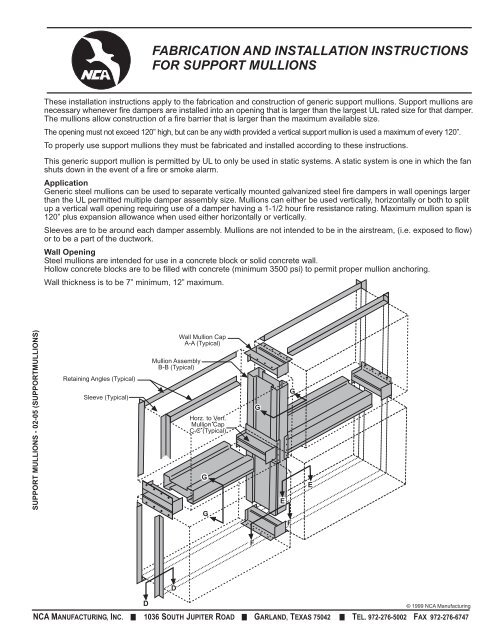
FABRICATION AND INSTALLATION INSTRUCTIONS<br />
FOR SUPPORT MULLIONS<br />
These <strong>installation</strong> <strong>instructions</strong> apply to the <strong>fabrication</strong> <strong>and</strong> construction of generic <strong>support</strong> <strong>mullions</strong>. Support <strong>mullions</strong> are<br />
necessary whenever fire dampers are installed into an opening that is larger than the largest UL rated size <strong>for</strong> that damper.<br />
The <strong>mullions</strong> allow construction of a fire barrier that is larger than the maximum available size.<br />
The opening must not exceed 120” high, but can be any width provided a vertical <strong>support</strong> mullion is used a maximum of every 120”.<br />
To properly use <strong>support</strong> <strong>mullions</strong> they must be fabricated <strong>and</strong> installed according to these <strong>instructions</strong>.<br />
This generic <strong>support</strong> mullion is permitted by UL to only be used in static systems. A static system is one in which the fan<br />
shuts down in the event of a fire or smoke alarm.<br />
Application<br />
Generic steel <strong>mullions</strong> can be used to separate vertically mounted galvanized steel fire dampers in wall openings larger<br />
than the UL permitted multiple damper assembly size. Mullions can either be used vertically, horizontally or both to split<br />
up a vertical wall opening requiring use of a damper having a 1-1/2 hour fire resistance rating. Maximum mullion span is<br />
120” plus expansion allowance when used either horizontally or vertically.<br />
Sleeves are to be around each damper assembly. Mullions are not intended to be in the airstream, (i.e. exposed to flow)<br />
or to be a part of the ductwork.<br />
Wall Opening<br />
Steel <strong>mullions</strong> are intended <strong>for</strong> use in a concrete block or solid concrete wall.<br />
Hollow concrete blocks are to be filled with concrete (minimum 3500 psi) to permit proper mullion anchoring.<br />
Wall thickness is to be 7” minimum, 12” maximum.<br />
SUPPORT MULLIONS - 02-05 (SUPPORTMULLIONS)<br />
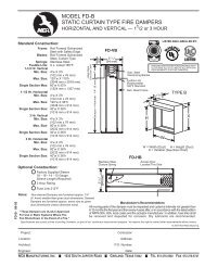
Retaining Angles (Typical)<br />
Sleeve (Typical)<br />
Mullion Assembly<br />
B-B (Typical)<br />
Wall Mullion Cap<br />
A-A (Typical)<br />
Horz. to Vert.<br />
Mullion Cap<br />
C-C (Typical)<br />
G<br />
G<br />
G<br />
E<br />
F<br />
G<br />
E<br />
F<br />
D<br />
D<br />
© 1999 <strong>NCA</strong> Manufacturing<br />
<strong>NCA</strong> MANUFACTURING, INC. 1036 SOUTH JUPITER ROAD GARLAND, TEXAS 75042 TEL. 972-276-5002 FAX 972-276-6747
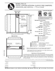
Support mullion assemblies consist of<br />
three basic parts: the wall mullion cap,<br />
the horizontal to vertical mullion cap<br />
<strong>and</strong> the mullion sections. Determine<br />
the number of each piece required to<br />
complete the <strong>installation</strong>.<br />
Table 1<br />
Dimensional In<strong>for</strong>mation<br />
Opening<br />
Width/Height D H<br />
12 11-1/2” 3-1/4”<br />
24 23-1/2” 3-3/8”<br />
36 33-3/8” 3-1/2”<br />
48 47-1/4” 3-5/8”<br />
60 59-1/8” 3-3/4”<br />
72 71” 3-7/8”<br />
84 82-7/8” 4”<br />
96 94-3/4” 4-1/8”<br />
108 106-3/4” 4-1/4”<br />
120 118-3/4” 4-3/8”<br />
E = Wall Thickness – 1/2”<br />
F = Wall Thickness + 1/4”<br />
2 1 13 /16 2<br />
SUPPORT MULLIONS - 02-05 (SUPPORTMULLIONS)<br />
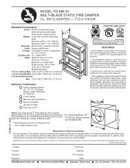
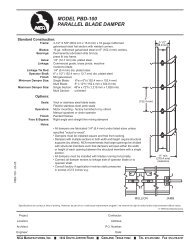
Fabrication of Wall Mullion Caps (Fig. A-A)<br />
Wall mullion caps must be constructed from 12 ga.<br />
steel with a minimum yield strength of 42,000 psi.<br />
1. Fabricate the <strong>for</strong>med section as shown to right.<br />
2. Shear the cap end plate to required dimensions.<br />
3. Weld the cap end plates to the <strong>for</strong>med section with<br />
1/8” fillet welds completely around the top edges<br />
of the <strong>for</strong>med section.<br />
4. Drill <strong>and</strong> countersink 8 holes (4 on each side <strong>for</strong> 1/4-20 flat<br />
head machine screws.<br />
Fabrication of Mullion Sections (Fig. B-B)<br />
Mullions must be constructed from 16 ga. steel with a minimum<br />
yield strength of 42,000 psi.<br />
Important: The “D’’ dimension shown has been calculated to<br />
include the necessary clearances required <strong>for</strong> thermal<br />
expansion in the <strong>mullions</strong>. The values can be found using the<br />
wall opening dimensions <strong>and</strong> tables on this page.<br />
1. Form two identical pieces of mullion section as shown.<br />
2. Connect the two mullion sections together. Use 3/16” steel<br />
bind rivets or 3/4” long intermittent welds 12” on center<br />
<strong>and</strong> a 6” maximum from both ends.<br />
Important: Both sides of the mullion piece should be fastened<br />
using the method described above.<br />
Detail A-A<br />
E/8<br />
Weld<br />
Detail B-B<br />
Formed Section<br />
End View<br />
3 3 /8<br />
E/4<br />
E/4<br />
E/4<br />
H<br />
E/8<br />
H<br />
Formed Section View (2 req’d.)<br />
3 /4<br />
2 C-4 2<br />
C=Wall Thickness<br />
D<br />
3 1 /2<br />
3/16” blind rivet (std.) or 3/4”<br />
long intermittent welds 12”<br />
on center, 6” max. from both<br />
ends, both sides of assembly.<br />
Wall Mullion Cap<br />
Assembled View<br />
3 1 /4<br />
Assembled View<br />
3 1 /4<br />
Cap End Plate<br />
(2 req’d.)<br />
7 /8<br />
H<br />
3/16” typical<br />
rivet location<br />
<strong>NCA</strong> MANUFACTURING, INC. 1036 SOUTH JUPITER ROAD GARLAND, TEXAS 75042 TEL. 972-276-5002 FAX 972-276-6747
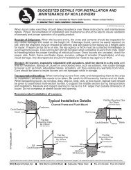
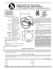
Fabrication of Horizontal to Vertical Mullion Caps (Fig. C-C)<br />
Horizontal to vertical mullion caps must be constructed from 12 ga. steel with a minimum yield strength of 42,000 psi.<br />
Important: The H, E <strong>and</strong> F dimensions shown have been calculated to provide the correct per<strong>for</strong>mance. The values can<br />
be found by using the wall opening dimensions <strong>and</strong> the tables on page 2.<br />
1. Form the horizontal mullion channel as shown.<br />
2. Drill 12, 3/16” dia. holes into the horizontal mullion channel using the dimensions shown.<br />
3. Form the center channel as shown.<br />
NOTE: If the center channel is to be made from two pieces, weld them together with an 1/8” fillet weld.<br />
4. Shear the end plates to the dimensions required.<br />
5. Weld the end plates to the center channel with 1/8” fillet welds completely around the top edges of the center section.<br />
One or two piece<br />
Horizontal Mullion Channel<br />
End Plate<br />
Center Channel<br />
Weld<br />
3/4<br />
3/16” dia.<br />
(12 holes)<br />
1-1/2<br />
H<br />
Side View<br />
Side View<br />
6<br />
F<br />
1/2<br />
1<br />
3/4<br />
1-1/2<br />
End View<br />
3-1/4<br />
E<br />
1 13 /16<br />
End View<br />
Top View<br />
1<br />
SUPPORT MULLIONS - 02-05 (SUPPORTMULLIONS)<br />
Detail C-C<br />
Weld<br />
Assembled View<br />
3/16<br />
Use 3/16 dia.. steel blind<br />
rivets at <strong>installation</strong><br />
1-3/8<br />
<strong>NCA</strong> MANUFACTURING, INC. 1036 SOUTH JUPITER ROAD GARLAND, TEXAS 75042 TEL. 972-276-5002 FAX 972-276-6747
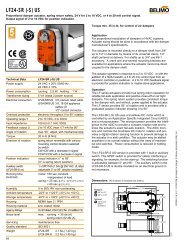
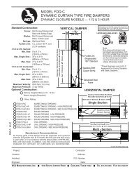
Mullion Installation<br />
Be<strong>for</strong>e the fire dampers are installed into the wall the <strong>mullions</strong> must first be<br />
anchored into the wall. The fire dampers may then be installed into the mullion<br />
assembly.<br />
To correctly attach the <strong>mullions</strong> to the wall follow these steps:<br />
1. Anchor wall mullion caps to wall using 1/4-20 x 5/16” long flat head steel<br />
bolts <strong>and</strong> 3/8” diameter by 1” long concrete expansion anchors (Hilti). If<br />
steel lintels are present, use two 1” long welds on each side of mullion caps.<br />
Note: End caps must be inserted into the ends of the <strong>mullions</strong> be<strong>for</strong>e they are<br />
anchored to the wall.<br />
2. Anchor horizontal mullion caps to vertical mullion caps with 3/16” diameter steel<br />
blind rivets in 12 places.<br />
Note: Mullion caps must be inserted into the ends of the <strong>mullions</strong> be<strong>for</strong>e they<br />
are anchored to the vertical <strong>mullions</strong> or wall.<br />
Fire Damper Installation<br />
Galvanized steel fire dampers must be UL classified <strong>for</strong> 1-1/2 hour fire resistance.<br />
They must be installed in galvanized steel sleeves <strong>and</strong> be retained by minimum<br />
1-1/2” x 1-1/2”, 16 ga. retaining angles on each side of the wall. Retaining angles<br />
must overlap <strong>mullions</strong> or wall by 1” minimum. Fasten to sleeve using 1/4” dia.<br />
bolts, 3/16” steel rivets, welding, or #10 sheet metal screws. All must be attached<br />
6” on centers, 2” maximum from corners. Do not fasten retaining angles to the<br />
wall or <strong>mullions</strong>. Mullions must be free to float.<br />
Total expansion clearance betwen sleeve <strong>and</strong> wall/mullion of 1/8” per foot of<br />
wall opening or mullion span should be allowed. Maximum clearance is 1-1/4”.<br />
Retaining<br />
Angles<br />
Wall<br />
1-1/2” x 1-1/2” min.<br />
10 ga. galv.<br />
Retaining Angle<br />
(typical)<br />
1” min.<br />
Detail E-E<br />
Detail D-D<br />
Mullion<br />
Sleeve<br />
Sleeve<br />
Mullion<br />
Mullion Cap<br />
SUPPORT MULLIONS - 02-05 (SUPPORTMULLIONS)<br />
G<br />
G<br />
G<br />
E<br />
G<br />
E<br />
1/4” Min.<br />
Detail F-F<br />
Detail G-G<br />
Wall Thickness<br />
7” min. & 12” max.<br />
End Cap<br />
Mullion<br />
FF<br />
D<br />
D<br />
F<br />
Manufacturer’s Recommendations<br />
All moving parts of the damper must be inspected <strong>and</strong> cycled at intervals not greater<br />
than every six months <strong>and</strong> in accordance with the latest edition of NFPA 90A, 92A, local<br />
codes <strong>and</strong> the actuator manufacturer. In addition, fuse links shall be removed <strong>and</strong><br />
inspected <strong>for</strong> corrosion. Dry lubricants are recommended.<br />
© 1999 <strong>NCA</strong> Manufacturing<br />
<strong>NCA</strong> MANUFACTURING, INC. 1036 SOUTH JUPITER ROAD GARLAND, TEXAS 75042 TEL. 972-276-5002 FAX 972-276-6747