BELIMO-GM24SR - NCA Manufacturing
BELIMO-GM24SR - NCA Manufacturing
BELIMO-GM24SR - NCA Manufacturing

You also want an ePaper? Increase the reach of your titles
YUMPU automatically turns print PDFs into web optimized ePapers that Google loves.
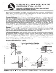
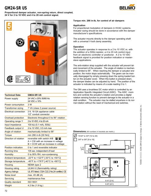
GM24-SR US<br />
Proportional damper actuator, non-spring return, direct coupled,<br />
24 V for 2 to 10 VDC and 4 to 20 mA control signal.<br />
®<br />
Torque min. 266 in-lb, for control of air dampers<br />
Application<br />
For proportional modulation of dampers in HVAC systems.<br />
Actuator sizing should be done in accordance with the damper<br />
manufacturer’s specifications.<br />
©<br />
The actuator mounts directly to the damper operating shaft<br />
with a universal V-bolt clamp assembly.<br />
Operation<br />
The actuator operates in response to a 2 to 10 VDC or, with<br />
the addition of a 500Ω resistor, a 4 to 20 mA control input<br />
from an electronic controller or positioner. A 2 to 10 VDC<br />
feedback signal is provided for position indication or masterslave<br />
applications.<br />
LISTED<br />
94D5<br />
TEMP. IND &<br />
REG. EQUIP.<br />
UL ®<br />
The anti-rotation strap supplied with the actuator will prevent lateral<br />
movement of the actuator. The angle of rotation is mechanically<br />
limited to 95°. When reaching the damper or actuator end<br />
position, the motor stops automatically. The gears can be manually<br />
disengaged by simply pressing down the spring loaded button<br />
on the actuator cover. When this button is pressed down,<br />
the damper blades can be adjusted by hand. The position of the<br />
actuator is indicated by means of a scale reading 0 to 1.<br />
Technical Data<br />
Power supply<br />
Power consumption<br />
Transformer sizing<br />
Electrical connection<br />
Overload protection<br />
Operating range Y<br />
Input impedance<br />
Feedback output U<br />
GM24-SR US<br />
24 VAC ± 20% 50/60 Hz<br />
24 VDC ± 10%<br />
3 W<br />
7 VA (class 2 power source)<br />
3 ft, 18 GA appliance cable<br />
1/2” conduit connector<br />
Electronic throughout 0 to 95° rotation<br />
2 to 10 VDC, 4 to 20 mA<br />
100 kΩ (0.1 mA), 500Ω<br />
2 to 10 VDC, 0.5 mA max<br />
Angle of rotation mechanically limited to 95°<br />
Torque<br />
Direction of rotation<br />
Position indication<br />
Running time<br />
Humidity<br />
Ambient temperature<br />
Storage temperature<br />
Housing NEMA type 2<br />
Housing rating<br />
Agency listings<br />
Noise level<br />
Servicing<br />
min 266 in-lb [30 Nm]<br />
reversible with switch A/B<br />
A = CW with an increase in voltage<br />
B = CCW with an increase in voltage<br />
0 to 1 and reversible indicator<br />
135 sec. independent of load<br />
5 to 95% RH, non-condensing<br />
-22°F to +122°F [-30°C to +50°C]<br />
-40°F to +176°F [-40°C to +80°C]<br />
UL94V-0 (flammability rating)<br />
UL 873 listed, CSA C22.2 No.24 certified, CE<br />
max. 45 dB (A)<br />
maintenance free<br />
Quality standard ISO 9001<br />
Weight<br />
4.2 lbs (1.9 kg.)<br />
The GM uses a brushless DC motor which is controlled by an<br />
Application Specific Integrated Circuit (ASIC). The ASIC monitors<br />
and controls the actuator’s rotation and provides a digital<br />
rotation sensing function to prevent damage to the actuator in a<br />
stall condition. The actuator may be stalled anywhere in its normal<br />
rotation without the need of mechanical end switches.<br />
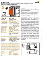
Dimensions (All numbers in brackets are metric.)<br />
15/32" to 3/4" [12 to 20]<br />
3/8" to 5/8" [9 to 16]<br />
2.12"<br />
[54]<br />
4.88"<br />
[124]<br />
1.02" [26]<br />
1.18" [30]<br />
8.43" [214]<br />
9.49" [241]<br />
3.15"<br />
[80]<br />
D012<br />
F20358 / 5 4 3 2 1 -01/04-10M-IG-Subject to change. © Belimo Aircontrols (USA), Inc.<br />
72
®<br />
GM24-SR US<br />
Proportional damper actuator, non-spring return, direct coupled,<br />
24 V for 2 to 10 VDC and 4 to 20 mA control signal.<br />
Accessories<br />
IRM-100 Input scaling module<br />
KH8 Universal crankarm<br />
KG10 Ball Joint<br />
NSV24 Battery back-up module<br />
P… Feedback potentiometer<br />
PTA-250 Pulse width modulation interface<br />
SGA24 Min. and/or manual positioner in NEMA 4 housing<br />
SGF24 Min. and/or man. positioner for flush panel mount<br />
S1,S2 Auxiliary switch<br />
Tool-01 10mm wrench<br />
ZAD24 Digital position indication<br />
ZDB-GM Angle of rotation limiter (Series 2)<br />
ZG-H2 Actuator operator handle<br />
ZG-GM2 Crankarm adaptor kit<br />
ZG-R01 500Ω resistor for 4 to 20 mA<br />
ZG-100 Universal mounting bracket<br />
ZG-101 Universal mounting bracket<br />
ZG-102 Multiple actuator mounting bracket<br />
ZG-103 Universal mounting bracket<br />
ZG-104 Universal mounting bracket<br />
ZS-100 Weather shield (metal)<br />
ZS-150 Weather shield (polycarbonate)<br />
ZS-260 Explosion-proof housing<br />
ZS-300 NEMA 4X housing<br />
NOTE: When using GM24-SR US actuators, use only the<br />
accessories listed on this page.<br />
GM24-SR US - Typical Specification:<br />
Control damper actuators shall be electronic direct coupled<br />
type which require no crankarm and linkage. Actuators shall<br />
be UL listed and CSA certified, have a 2 year warranty, and<br />
be manufactured under ISO 9001 International Quality Control<br />
Standards. Actuators shall have reversing switch and gear<br />
disengagement button on the cover. Actuators shall use a<br />
brushless DC motor and be protected from overload at all<br />
angles of rotation. Run time shall be constant and independent<br />
of torque. The actuator must provide proportional damper<br />
control in response to a 2 to 10 VDC or, with the addition of a<br />
500Ω resistor, a 4 to 20 mA control input from an electronic<br />
controller or positioner. A 2 to 10 VDC feedback signal shall<br />
be provided for position indication or master-slave applications.<br />
Actuators shall be as manufactured by Belimo.<br />
Model<br />
Multiple actuators mounted to shaft<br />
Maximum quantity per shaft<br />
GM24 US 2<br />
GM24-SR US 2<br />
GM<br />
F20358 / 5 4 3 2 1 -01/04-10M-IG-Subject to change. © Belimo Aircontrols (USA), Inc.<br />
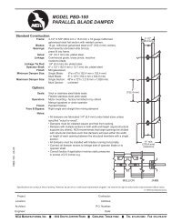
Wiring diagrams<br />
1 Provide overload protection and disconnect as required.<br />
2<br />
1<br />
Line<br />
Volts<br />
24 VAC Transformer<br />
2 to 10 VDC (–)<br />
Control Signal (+)<br />
Actuators may be connected in parallel. Power consumption<br />
and input impedance must be observed.<br />
0 to 10 VDC control of GM24-SR US<br />
1 Common<br />
2 + Hot<br />
3 Y Input, 2 to 10V<br />
1<br />
5 U Output 2 to 10V<br />
A<br />
2<br />
B GM24-SR US<br />
W072<br />
1<br />
2<br />
3<br />
4<br />
1<br />
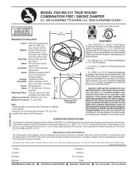
Line<br />
Volts<br />
24 VAC Transformer<br />
0 to 20 mA (–)<br />
Control Signal (+)<br />
2 to 10 VDC (–)<br />
Feedback Signal (+)<br />
2<br />
Ω<br />
500Ω<br />
4<br />
1 Common<br />
2 + Hot<br />
3 Y Input, 2 to 10V<br />
5 U Output 2 to 10V<br />
3 A<br />
To other<br />
actuators B GM24-SR US<br />
Provide overload protection and disconnect as required.<br />
Connect actuator common (wire 1) to negative (–) leg<br />
of control circuits only.<br />
Up to 4 actuators may be connected in parallel. With 4<br />
actuators wired to one 500Ω resistor, a +2% shift of<br />
control signal may be required. Power consumption<br />
must be observed.<br />
The 500Ω resistor converts the 4 to 20 mA control signal<br />
to 2 to 10 VDC.<br />
1<br />
5<br />
W073<br />
5<br />
Actuator may also be powered by 24 VDC.<br />
4 to 20 mA control of GM24-SR US with 2 to 10 VDC feedback<br />
output.<br />
73