SCD-LL-57 - NCA Manufacturing
SCD-LL-57 - NCA Manufacturing
SCD-LL-57 - NCA Manufacturing

Create successful ePaper yourself
Turn your PDF publications into a flip-book with our unique Google optimized e-Paper software.
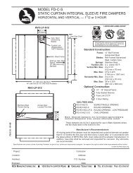
MODEL <strong>SCD</strong>-<strong>LL</strong>-<strong>57</strong><br />
LOW LEAKAGE<br />
STEEL CONTROL DAMPER<br />
<strong>SCD</strong>-<strong>LL</strong>-<strong>57</strong> - 02-05<br />
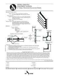
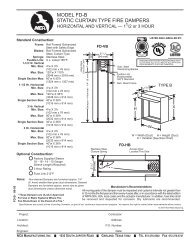
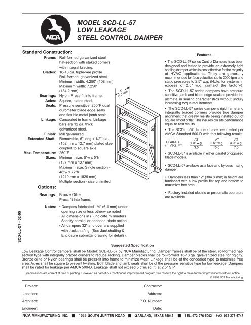
Standard Construction:<br />
Frame: Roll-formed galvanized steel<br />
hat-section with staked corners<br />
with integral bracing.<br />
Blades: 16-18 ga. triple-vee profile<br />
Roll-formed, galvanized steel<br />
Minimum width: 4.250" (108 mm)<br />
Maximum width: 7.250"<br />
(184.2 mm)<br />
Bearings: Nylon. Press-fit into frame.<br />
Axles: Square, plated steel.<br />
Seals: Pressure sensitive, 250°F dual<br />
durometer blade edge seals<br />
and flexible metal jamb seals.<br />
Linkage: Concealed in frame. Linkage<br />
bars are 12 ga. thick<br />
galvanized steel.<br />
Finish: Mill galvanized.<br />
Extended Shaft: Removable, 6" long x 1/2” dia.<br />
(152 mm x 12.7 mm) plated steel<br />
coupled to square axle.<br />
Max. Temperature: 250°F<br />
Sizes: Minimum size: 5"w x 5"h<br />
(127 mm x 127 mm)<br />
Maximum size: Single section -<br />
48"w x 72"h<br />
(1219 mm x 1829 mm)<br />
Multiple section - size unlimited<br />
Options:<br />
Bearings:<br />
Notes:<br />
Bronze Oilite.<br />
Press fit into frame.<br />
5"<br />
(127 mm)<br />
• Dampers fabricated 1/4" (6.4 mm) under<br />
opening size unless otherwise noted<br />
• All dimensions in ( ) indicate millimeters<br />
Specify parallel or opposed blade action.<br />
• All dampers 32" and over are supplied<br />
with Jackshatfing. (See Jackshafting &<br />
Enclosure submittal drawing for details).<br />
Suggested Specification<br />
Features<br />
• The <strong>SCD</strong>-<strong>LL</strong>-<strong>57</strong> series Control Dampers have been<br />
designed and tested to provide an extremely tight<br />
sealing damper which is cost effective for the majority<br />
of HVAC applications. They are generally<br />
recommended for face velocities up to 2000 fpm and<br />
static pressures to 2.5" w.g. (Note: for systems in<br />
excess of 2.5" w.g. contact the factory).<br />
• The <strong>SCD</strong>-<strong>LL</strong>-<strong>57</strong> series dampers have pressure<br />
sensitive jamb and blade edge seals to provide the<br />
ultimate in sealing characteristics without unduly<br />
increasing torque requirements.<br />
• The <strong>SCD</strong>-<strong>LL</strong>-<strong>57</strong> series damper's rigid frame and<br />
integrally braced corners provide true damper<br />
alignment that greatly resists being installed out of<br />
square or out of flat. This insures on site performance<br />
equal to test results.<br />
• The <strong>SCD</strong>-<strong>LL</strong>-<strong>57</strong> dampers have been tested per<br />
AMCA Standard 500-D with the following results:<br />
LEAKAGE<br />
cfm/SQ. FT.<br />
AT<br />
1.0" w.g.<br />
3.5<br />
AT<br />
2.5" w.g.<br />
5.0<br />
AT<br />
4.0" w.g.<br />
7.0<br />
• <strong>SCD</strong>-<strong>LL</strong>-<strong>57</strong> is available in either parallel or opposed<br />
blade models.<br />
• <strong>SCD</strong>-<strong>LL</strong>-<strong>57</strong> available as a face and by-pass mixing<br />
damper.<br />
• Dampers less than 12" (304.8 mm) in height are<br />
furnished with a low profile flat top and bottom to<br />
maximize free area.<br />
• Factory installed electric or pneumatic operators<br />
are available.<br />
Low Leakage Control dampers shall be Model: <strong>SCD</strong>-<strong>LL</strong>-<strong>57</strong> by <strong>NCA</strong> <strong>Manufacturing</strong>. Damper frames shall be of the steel, roll-formed hatsection<br />
type with integrally braced corners to reduce racking. Damper blades shall be roll-formed 16-18 ga. galavanized steel for rigidity.<br />
Bronze oilite or Nylon bearings shall be press-fit into frame to minimize wear. Linkage shall be of the concealed type to maximize free<br />
area. Axles shall be square to prevent twisting. Both blade and jamb seals shall be of the pressure sensitive type for low leakage. Dampers<br />
shall be rated for leakage per AMCA 500-D. Leakage shall not exceed 5 cfm/sq. ft. at 2.5" S.P.<br />
Specifications are correct at time of printing. However, as part of our ‘continuous improvement program,’ we reserve the right to make further improvements without notice.<br />
© 1999 <strong>NCA</strong> <strong>Manufacturing</strong><br />
Project:<br />
Location:<br />
Architect:<br />
Engineer:<br />
Contractor:<br />
Address:<br />
P.O. Number:<br />
Date:<br />
<strong>NCA</strong> MANUFACTURING, INC. 1036 SOUTH JUPITER ROAD GARLAND, TEXAS 75042 TEL. 972-276-5002 FAX 972-276-6747
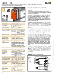
MODEL <strong>SCD</strong>-<strong>LL</strong>-<strong>57</strong><br />
LOW LEAKAGE<br />
STEEL CONTROL DAMPER<br />
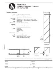
PRESSURE DROP - INCHES OF WATER (In. W.C.)<br />
DAMPER SIZE 36 x 36<br />
DAMPER SIZE 24 x 24<br />
DAMPER SIZE 12 X 12<br />
© 1999 <strong>NCA</strong> <strong>Manufacturing</strong><br />
Pressure drop testing was conducted by an independent laboratory in accordance with the AMCA Standard 500-D, Fig. 5.3<br />
ductwork upstream & downstream<br />
2.5<br />
2<br />
1.5<br />
1.0 .9<br />
.8<br />
.7<br />
.6<br />
.5<br />
.4<br />
.3<br />
.25<br />
.2<br />
.15<br />
.1<br />
.09<br />
.08<br />
.07<br />
.06<br />
.05<br />
.04<br />
.03<br />
.025<br />
.02<br />
.015<br />
2.5<br />
2<br />
1.5<br />
1.0 .9<br />
.8<br />
.7<br />
.6<br />
.5<br />
.4<br />
.3<br />
.25<br />
.2<br />
.15<br />
.1<br />
.09<br />
.08<br />
.07<br />
.06<br />
.05<br />
.04<br />
.03<br />
.025<br />
.02<br />
.015<br />
PRESSURE DROP<br />
2.5<br />
2<br />
1.5<br />
1.0 .9<br />
.8<br />
.7<br />
.6<br />
.5<br />
.4<br />
.3<br />
.25<br />
.2<br />
.15<br />
.1<br />
.09<br />
.08<br />
.07<br />
.06<br />
.05<br />
.04<br />
.03<br />
.025<br />
.02<br />
.015<br />
<strong>SCD</strong>-<strong>LL</strong>-<strong>57</strong> - 02-05<br />
.01<br />
100 150 200 300 400 500 700 900 1500 2000 3000 4000 6000<br />
1000<br />
VELOCITY THROUGH FACE AREA<br />
Pressure (In. W.G.)<br />
5<br />
4<br />
3<br />
2<br />
1<br />
PRESSURE LIMITATIONS<br />
0<br />
0 12 24 36 48<br />
Section Width (In.)<br />
.01<br />
100 150 200 300 400 500 700 900 1500 2000 3000 4000 6000<br />
1000<br />
VELOCITY THROUGH FACE AREA<br />
Pressure & Velocity<br />
Limitations presented in<br />
the adjoining graphs are<br />
conservative in order to<br />
avoid mis-applications.<br />
Please contact factory for<br />
application guidance if<br />
your requirements<br />
exceed published<br />
limitations.<br />
Velocity (FPM)<br />
.01<br />
3000<br />
2500<br />
2000<br />
1500<br />
100 150 200 300 400 500 700 900 1500 2000 3000 4000 6000<br />
1000<br />
VELOCITY THROUGH FACE AREA<br />
VELOCITY LIMITATIONS<br />
1000<br />
0 12 24 36 48<br />
LEAKAGE<br />
DAMPER SIZE 36 x 48<br />
Section Width (In.)<br />
10<br />
98<br />
7<br />
Leakage Performance test was<br />
conducted by an independent<br />
laboratory in accordance with AMCA<br />
Standard 500-D and is expressed as<br />
CFM/SQ. FT. of damper face area.<br />
STATIC PRESSURE<br />
6<br />
5<br />
4<br />
3<br />
2.5<br />
2<br />
1.5<br />
1.0<br />
1 1.5 2 3 4 5 7 9 15 20 30 40 60<br />
10<br />
LEAKAGE IN CFM/SQ. FT.<br />
<strong>NCA</strong> MANUFACTURING, INC. 1036 SOUTH JUPITER ROAD GARLAND, TEXAS 75042 TEL. 972-276-5002 FAX 972-276-6747