Submittal - 2-Position, Spring Return, No. 3 Pneumatic Actuator, 8 sq ...
Submittal - 2-Position, Spring Return, No. 3 Pneumatic Actuator, 8 sq ...
Submittal - 2-Position, Spring Return, No. 3 Pneumatic Actuator, 8 sq ...

You also want an ePaper? Increase the reach of your titles
YUMPU automatically turns print PDFs into web optimized ePapers that Google loves.
Technical Instructions<br />
Document <strong>No</strong>. 152-040P25<br />
Rev. 4, May, 2001<br />
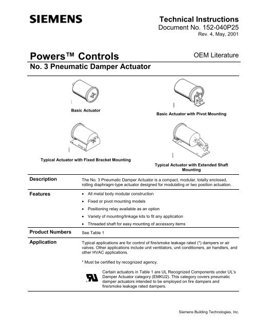
Powers Controls<br />
<strong>No</strong>. 3 <strong>Pneumatic</strong> Damper <strong>Actuator</strong><br />
OEM Literature<br />
Basic <strong>Actuator</strong><br />
Basic <strong>Actuator</strong> with Pivot Mounting<br />
Typical <strong>Actuator</strong> with Fixed Bracket Mounting<br />
Typical <strong>Actuator</strong> with Extended Shaft<br />
Mounting<br />
Description<br />
Features<br />
The <strong>No</strong>. 3 <strong>Pneumatic</strong> Damper <strong>Actuator</strong> is a compact, modular, totally enclosed,<br />
rolling diaphragm-type actuator designed for modulating or two position actuation.<br />
• All metal body modular construction<br />
• Fixed or pivot mounting models<br />
• <strong>Position</strong>ing relay available as an option<br />
• Variety of mounting/linkage kits to fit any application<br />
• Threaded shaft for easy mounting of accessory items<br />
Product Numbers See Table 1<br />
Application<br />
Typical applications are for control of fire/smoke leakage rated (*) dampers or air<br />
valves. Other applications include unit ventilators, unit conditioners, air handlers, and<br />
other HVAC applications.<br />
* Must be certified by recognized agency.<br />
Certain actuators in Table 1 are UL Recognized Components under UL’s<br />
Damper <strong>Actuator</strong> category (EMKU2). This category covers pneumatic<br />
damper actuators intended to be employed on fire dampers and<br />
fire/smoke leakage rated dampers.<br />
Siemens Building Technologies, Inc.
Technical Instructions<br />
Document Number 152-040P25<br />
Rev. 4, May, 2001<br />
Powers Controls <strong>No</strong>. 3 <strong>Pneumatic</strong> Damper <strong>Actuator</strong><br />
Table 1. Product Numbers for <strong>No</strong>. 3 <strong>Pneumatic</strong> Damper <strong>Actuator</strong>s.<br />
Description Mounting Style 3-7 psi<br />
(21-48 kPa)<br />
Part Number<br />
<strong>No</strong>minal <strong>Spring</strong> Range<br />
5-10 psi<br />
(35-69 kPa)<br />
8-13 psi<br />
(55-90 kPa)<br />
Basic <strong>Actuator</strong> only — 331-4326*<br />
331-4327*<br />
331-4526*<br />
331-4527*<br />
331-4826*<br />
331-4827*<br />
<strong>Actuator</strong> with pivot bracket Pivot 331-4322 331-4522 331-4822<br />
<strong>Actuator</strong> with front mounted fixed<br />
bracket<br />
Fixed bracket 331-4323 331-4523 331-4823<br />
<strong>Actuator</strong> with clevis Basic 331-4324* 331-4524* 331-4824*<br />
<strong>Actuator</strong> with clevis and positioner relay Basic ‡ ‡ 332-4824<br />
<strong>Actuator</strong> with pivot bracket, pivot post,<br />
clevis, and miscellaneous hardware<br />
<strong>Actuator</strong> with pivot bracket, pivot post,<br />
clevis, crank assembly, extended shaft<br />
mounting plate, damper drive blade,<br />
and mounting hardware<br />
* UL Recognized Component.<br />
‡ Available upon request.<br />
Pivot 331-4351 331-4551* 331-4851*<br />
331-4829*<br />
331-4841*<br />
Extended shaft mounting — — 331-4821*<br />
Specifications Effective diaphragm area 8 inches 2 (51.6 cm 2 )<br />
Stroke<br />
2-3/4 inches (70 mm)<br />
Housing (totally enclosed)<br />
Aluminum<br />
Stem<br />
Plated steel<br />
Diaphragm<br />
Ozone resistant rubber<br />
<strong>Spring</strong><br />
Steel<br />
Cup<br />
Zytel<br />
Maximum air pressure<br />
25 psig (172 kPa)<br />
<strong>No</strong>minal spring ranges See Table 1<br />
Operating temperature<br />
-20 to 160°F (-29 to 71°C)<br />
Air Connection<br />
Straight barb fitting for<br />
1/4 inch O.D. plastic tubing<br />
installed in 1/8 inch<br />
NPT opening<br />
Type of Mounting<br />
Fixed or pivot<br />
Thrust and Torque Rating See Table 2<br />
Shipping Weight:<br />
Basic <strong>Actuator</strong><br />
1.3 lbs. (0.58 kg)<br />
<strong>Actuator</strong> with Extended Shaft Mounting 3.1 lbs. (1.4 kg)<br />
<strong>Actuator</strong> with Fixed Bracket<br />
2.5 lbs. (1.1 kg)<br />
<strong>Actuator</strong> with Fixed Bracket and Clevis 2.7 lbs. (1.2 kg)<br />
<strong>Actuator</strong> with Extended Shaft Mounting<br />
and <strong>Position</strong>ing Relay<br />
4.8 lbs. (2.2 kg)<br />
Dimensions See Figures 4 through 8<br />
Agency Approvals<br />
Complies with UL555 and UL555S<br />
Page 2<br />
Siemens Building Technologies, Inc.
Powers Controls <strong>No</strong>. 3 <strong>Pneumatic</strong> Damper <strong>Actuator</strong><br />
Technical Instructions<br />
Document Number 152-040P25<br />
Rev. 4, May, 2001<br />
NOTE: The <strong>No</strong>. 3 <strong>Pneumatic</strong> Damper <strong>Actuator</strong> does not require any periodic cycling. However, it is strongly<br />
suggested that all systems are functionally checked periodically, and per local codes and ordinances.<br />
Accessories<br />
Linkage kit (4-inch link and crank) 331-958<br />
Linkage kit (4-inch rod, ball joint and crank) 331-947<br />
Damper shaft crank, selectable radius, 45°,<br />
60°, and 90°, angular rotation for 3/8 to 1/2-inch<br />
(9.5 to 13 mm ) diameter damper shafts 331-941<br />
Damper shaft crank adjustable radius<br />
3/4 to 2-7/8-inch (19 to 73 mm) for 1/2 inch<br />
(13 mm) diameter damper shaft 331-795<br />
Damper shaft crank adjustable radius<br />
3/4 to 4-5/8-inch (19 to 177 mm) for<br />
3/8 inch (9 mm) diameter damper shaft 331-805<br />
Damper shaft extension 1/2 inch × 9 inch long 333-042<br />
Damper shaft extension 1/2 inch shaft 331-631<br />
Damper shaft extension Adapter for 3/8-inch shaft 331-632<br />
Pivot mounting bracket only 333-134<br />
Pivot mounting kit (bracket and three<br />
mounting screws) 333-148<br />
Pivot post 333-139<br />
Fixed mounting bracket 331-916<br />
Extended shaft mounting plate 331-033<br />
Clevis, steel 333-207<br />
Clevis pin 331-293<br />
Hitch pin 331-807<br />
Damper actuator push rods:<br />
12 inch 338-041<br />
15 inch 338-042<br />
18 inch 338-043<br />
24 inch 338-044<br />
36 inch 338-045<br />
48 inch 338-046<br />
Damper blade rocker arm 333-034<br />
<strong>Position</strong>ing relay 147-2000<br />
Relay mounting kit 147-104<br />
Siemens Building Technologies, Inc. Page 3
Technical Instructions<br />
Document Number 152-040P25<br />
Rev. 4, May, 2001<br />
Powers Controls <strong>No</strong>. 3 <strong>Pneumatic</strong> Damper <strong>Actuator</strong><br />
<strong>No</strong>minal<br />
<strong>Spring</strong><br />
Range<br />
3 To 7 psi<br />
(21 to 48 kPa)<br />
5 to 10 psi<br />
(35 to 69 kPa)<br />
8-13 psi<br />
(55 to 90 kPa)<br />
Table 2. Thrust Torque Ratings.<br />
Maximum Thrust lbs. (N)<br />
Full Stroke Forward<br />
15 psi<br />
(103<br />
kPa)<br />
64<br />
(285)<br />
40<br />
(178)<br />
16<br />
(71)<br />
18 psi<br />
(124<br />
kPa)<br />
88<br />
(391)<br />
64<br />
(285)<br />
40<br />
(178)<br />
25 psi<br />
(172<br />
kPa)<br />
144<br />
(641)<br />
120<br />
(534)<br />
96<br />
(427)<br />
<strong>Spring</strong><br />
<strong>Return</strong><br />
(<strong>No</strong> Stroke)<br />
0 psig<br />
(0 kPa)<br />
* With maximum hysteresis of 2.5 psi (17.2 kPa) @ 90° rotation.<br />
Gradual<br />
Operation<br />
Torque Rating* lb/in (Nm)<br />
15 psi<br />
(103<br />
kPa)<br />
2-<strong>Position</strong> Operation<br />
18 psi<br />
(124<br />
kPa)<br />
25 psi<br />
(172<br />
kPa)<br />
24 (107) 10 (1.1) 20.2 (2.3) 20.2 (2.3) 20.2 (2.3)<br />
40 (178) 10 (1.1) 33.6 (3.8) 33.6 (3.8) 33.6 (3.8)<br />
64 (285) 10 (1.1) 13.4 (1.5) 33.6 (3.8) 53.8 (6.1)<br />
Operation<br />
Figure 1.<br />
Table 3. <strong>No</strong>. 3 Damper <strong>Actuator</strong> with Optional <strong>Position</strong>er Relay 147-2000<br />
and Relay Mounting Kit 147-104. (See Figure 1)<br />
Item Description Item Description<br />
1 <strong>Position</strong>ing relay mounting bracket 7 <strong>Spring</strong> arm<br />
2 Feedback spring−zinc plate or 8 3/8−24 hex nut<br />
yellow chr.<br />
3 Adjusting screw 1-3/4 inch<br />
(44 mm) long<br />
9 Clevis<br />
4 Wing nut 10 <strong>No</strong>. 10 – 16, 1/2-inch (13-mm)<br />
slotted hex screw<br />
5 Lock washer 11 90° Elbow connector<br />
6 Flat washer<br />
Page 4<br />
Siemens Building Technologies, Inc.
Powers Controls <strong>No</strong>. 3 <strong>Pneumatic</strong> Damper <strong>Actuator</strong><br />
Technical Instructions<br />
Document Number 152-040P25<br />
Rev. 4, May, 2001<br />
Operation,<br />
Continued<br />
NO. 8<br />
Figure 2.<br />
3/8 THROUGH 1/2 IN.<br />
(10 THROUGH 13 MM)<br />
DIAMETER<br />
Figure 3.<br />
Table 4. Extended Shaft Mounting with Pivot and Mounting Plate.<br />
Item Description Part Numbers<br />
1 Nuts (2) 041-133K<br />
2 Lock washers (2) 046-017K<br />
3 E-ring 047-051J<br />
4 Pivot shaft (post) 333-139<br />
5 Jamb nut 041-143K<br />
6 Clevis 333-207<br />
7 Hitch pin 331-807<br />
8 Clevis pin 331-293<br />
9 Crank assembly kit 331-941<br />
10 Extended shaft <strong>No</strong>. 3 actuator mounting plate 331-033<br />
NOTE: Kit number 331-101 including items 1, 2, 3, and 4, above, plus pivot bracket<br />
and self tapping screws, have a minimum order quantity of 50 pieces.<br />
Dimensions<br />
Figure 4. Dimensions Shown in Inches (mm).<br />
Siemens Building Technologies, Inc. Page 5
Technical Instructions<br />
Document Number 152-040P25<br />
Rev. 4, May, 2001<br />
Powers Controls <strong>No</strong>. 3 <strong>Pneumatic</strong> Damper <strong>Actuator</strong><br />
Dimensions,<br />
Continued<br />
Figure 5. Basic <strong>Actuator</strong><br />
Figure 6. Mounting Plate.<br />
Figure 7. Pivot Mount.<br />
Figure 8. Fixed Bracket Mount.<br />
Information in this publication is based on current specifications. The company reserves the right to make changes in specifications and<br />
models as design improvements are introduced. Powers is a trademark of Siemens Building Technologies, Inc. Other product or company<br />
names mentioned herein may be the trademarks of their respective owners. © 2001 Siemens Building Technologies, Inc.<br />
Siemens Building Technologies, Inc.<br />
Landis & Staefa Division<br />
1000 Deerfield Parkway<br />
Buffalo Grove, IL 60089-4513<br />
U.S.A.<br />
Your feedback is important to us. If you have<br />
comments about this document, please send<br />
them to technical.editor@sbt.siemens.com<br />
Document <strong>No</strong>. 152-040P25<br />
Printed in the U.S.A.<br />
Page 6