model fsd-af-s-212 and model fsd-af-s-232 - NCA Manufacturing
model fsd-af-s-212 and model fsd-af-s-232 - NCA Manufacturing
model fsd-af-s-212 and model fsd-af-s-232 - NCA Manufacturing

You also want an ePaper? Increase the reach of your titles
YUMPU automatically turns print PDFs into web optimized ePapers that Google loves.
STATE OF CALIFORNIA<br />
FSD-AF-S-<strong>212</strong> - 05-08<br />
St<strong>and</strong>ard Construction:<br />
Frame:<br />
Blades:<br />
Bearings:<br />
Axles:<br />
Seals:<br />
Linkage:<br />
Sleeve:<br />
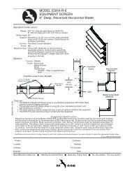
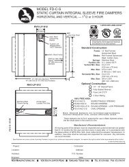
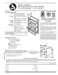
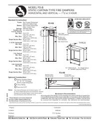
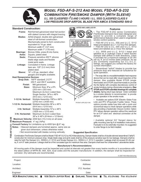
MODEL FSD-AF-S-<strong>212</strong> AND MODEL FSD-AF-S-<strong>232</strong><br />
COMBINATION FIRE/SMOKE DAMPER (WITH SLEEVE)<br />
U.L. 555 CLASSIFIED 1 1 /2 AND 3 HOURS / U.L. 555S CLASSIFIED CLASS II<br />
LOW PRESSURE DROP AIRFOIL BLADE PER AMCA STANDARD 500-D<br />
Roll-formed galvanized steel hat-section<br />
with staked corners with integral bracing.<br />
Airfoil-shaped, double skin galvanized<br />
steel of roll-formed construction.<br />
Mechanically joined to form construction<br />
equivalent to 14 ga. steel.<br />
Minimum width 5" (127 mm)<br />
Maximum width 7" (178 mm)<br />
Bronze Oilite, press-fit into frame.<br />
Square, plated steel.<br />
Pressure sensitive 450°F silicone<br />
blade edge seals <strong>and</strong> flexible<br />
metal jamb seals.<br />
Concealed in frame. Linkage<br />
bars are .125" (3.2 mm) thick<br />
plated steel.<br />
16” x 20 ga. st<strong>and</strong>ard, other<br />
gauges <strong>and</strong> lengths available.<br />
Heat Ressponsive Devices:<br />
Snap Disk: 165°F ° st<strong>and</strong>ard, ° <strong>212</strong>°F,<br />
250 F, <strong>and</strong> 350 F available.<br />
Finish: Mill galvanized.<br />
Sizes: Minimum Size: 8"w x 8"h<br />
(203 mm x 203 mm)<br />
Maximum UL/ULC Listed Size:<br />
Single Section: 36"w x 48"h<br />
(914 mm x 1219 mm)<br />
1-1/2 Hr. Vertical: Multiple Assembly-108"w x 96"h<br />
(2743 mm x 2438 mm)<br />
1-1/2 Hr. Horizontal: Multiple Assembly-36”w x 48”h<br />
(914 mm x 1219 mm)<br />
3 Hr. Vertical: Multiple Assembly-72”w x 48”h<br />
(1828 mm x 1219 mm)<br />
3 Hr. Horizontal: Maximum UL/ULC Listed Size:<br />
36”w X 48”h (914mm x 1219mm)<br />
Maximum Velocity: 2000 fpm (10.2 m/s) on all sizes<br />
Maximum Pressure: 4” wg (1kPa)<br />
Consult Factory for Limitations up to 4000 fpm @ 6” wg.<br />
Notes: • Sleeved dampers are furnished approx. same size as<br />
given duct dimension, unless otherwise noted.<br />
• Not recommended with blades running vertically.<br />
LISTING<br />
STATE<br />
FIRE<br />
S E R V<br />
5"<br />
(127 mm)<br />
M A R SH A L L<br />
IC E<br />
LISTED AND LABELLED BY:<br />
U.L. 555S CLASSIFIED<br />
AT 250°F OR 350°F<br />
DEPENDING UPON<br />
MOTOR/OPERATOR<br />
*SEE MOTOR/OPERATOR SCHEDULE<br />
16” MINIMUM BASED ON<br />
5” WALL OR FLOOR<br />
PATENT APPLIED FOR<br />
Suggested Specification<br />
Features<br />
• The FSD-AF-S-2X2 series Combination<br />
Fire/Smoke Dampers have been designed <strong>and</strong><br />
tested to provide a complete range of<br />
performance features when used in engineered<br />
smoke control systems.<br />
• FSD-AF-<strong>212</strong> is U.L. 555 <strong>and</strong> U.L.C. S112<br />
listed <strong>and</strong> labeled as a 1-1/2 hour fire damper.<br />
• FSD-AF-<strong>232</strong> is U.L. 555 <strong>and</strong> U.L.C. S112<br />
listed <strong>and</strong> labeled as a 3 hour fire damper.<br />
• U.L. 555S <strong>and</strong> U.L.C. S112.1 listed <strong>and</strong><br />
labelled as a Leakage Class II rated Smoke<br />
Damper with airflow in both directions. Class<br />
II provides for a maximum leakage of 20 cfm<br />
per sq. ft. at 4.0 inches static pressure. As we<br />
are constantly exp<strong>and</strong>ing our U.L./U.L.C.<br />
listings, we suggest you contact the factory for<br />
current information.<br />
• Streamlined "airfoil" blades to provide low<br />
pressure drop <strong>and</strong> reduced air turbulence for<br />
quiet operation.<br />
• The snap disk is a reusable/resettable heat response<br />
device that can be reset <strong>af</strong>ter visual inspection of the<br />
damper. Also available Model STO/R (single<br />
thermostat) <strong>and</strong> DTO/R (dual thermostat) to provide<br />
the fire fighter with complete discretionary control of<br />
smoke functions during a fire/smoke emergency. (See<br />
STO/R <strong>and</strong> DTO/R submittal drawings for complete<br />
details). Spring return type damper motor controlled<br />
by a smoke detector is recommended to provide<br />
proper operation in the smoke mode.<br />
• Available are options EGF (Electric Globe Fuse<br />
Link) <strong>and</strong> PFV (Pneumatic Fusible Valve). These<br />
options provide visible fuse links with a quick <strong>and</strong><br />
economical ways to check damper operations while<br />
also providing a Systematic Closure Control. Option<br />
PFV allows damper operation without the need/cost<br />
for an E-P valve <strong>and</strong> electrical connection at the<br />
damper.<br />
• Available optional 3/4” flanged sleeve for<br />
grille mounting (see fig.9 of installation instructions).<br />
If actuator is to be externally mounted, it is suggested<br />
to order flange to be field installed.<br />
Combination Fire/Smoke Dampers shall be Model: FSD-AF-S-<strong>212</strong> by <strong>NCA</strong> <strong>Manufacturing</strong>. Damper blades shall be of double-skinned streamlined ("airfoil")<br />
construction for minimum pressure drop. Single blade edge <strong>and</strong> jamb seals shall be of the pressure sensitive type for low leakage. Dampers shall be<br />
rated for both Fire Damper (U.L. 555S/U.L.C. S112) <strong>and</strong> Smoke Damper (U.L. 555S/U.L.C. S112.1) operation. Leakage shall not exceed 20 cfm per<br />
sq. ft. at 4.0" static pressure. Linkage shall be of the concealed type for maximum free area. Dampers shall bear the Underwriters' Laboratories labels.<br />
Manufacturer’s Recommendations<br />
All moving parts of the damper must be inspected <strong>and</strong> cycled at intervals not greater than every twelve months or in accordance with<br />
the latest edition of NFPA 80, 90A, 92A, local codes <strong>and</strong> the actuator manufacturer. In addition, the damper shall be inspected for<br />
corrosion. Dry lubricants are recommended.<br />
© 2007 <strong>NCA</strong> <strong>Manufacturing</strong><br />
Project:<br />
Location:<br />
Architect:<br />
Contractor:<br />
Address:<br />
P.O. Number:<br />
Engineer:<br />
<strong>NCA</strong> MANUFACTURING, INC. 1036 SOUTH JUPITER ROAD GARLAND, TEXAS 75042 TEL. 972-276-5002 FAX 972-276-6747<br />
Date:
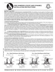
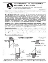
PRESSURE DROP - INCHES OF WATER (In. W.C.)<br />
© 2007 <strong>NCA</strong> <strong>Manufacturing</strong><br />
Pressure drop testing was done by an independent laboratory to the AMCA St<strong>and</strong>ard 500-D, Fig. 5.3<br />
ductwork upstream & downstream.<br />
1.0<br />
.9<br />
.8<br />
.7<br />
.6<br />
.5<br />
.4<br />
.3<br />
.25<br />
.2<br />
.15<br />
.1<br />
.09<br />
.08<br />
.07<br />
.06<br />
.05<br />
.04<br />
.03<br />
.025<br />
.02<br />
.015<br />
.01<br />
DAMPER SIZE 36 x 36<br />
MODEL FSD-AF-S-<strong>212</strong> AND MODEL FSD-AF-S-<strong>232</strong><br />
COMBINATION FIRE/SMOKE DAMPER (WITH SLEEVE)<br />
U.L. 555 CLASSIFIED 1 1 /2 AND 3 HOURS / U.L. 555S CLASSIFIED CLASS II<br />
LOW PRESSURE DROP AIRFOIL BLADE PER AMCA STANDARD 500-D<br />
100 150 200 300 400 500 700 900 1500 2000 3000 4000 6000<br />
1000<br />
VELOCITY THROUGH FACE AREA<br />
PERFORMANCE DATA<br />
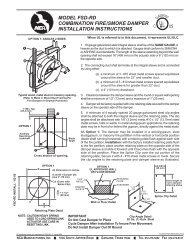
When the actuator is externally<br />
mounted <strong>and</strong> the wall thickness<br />
exceeds 5 inches, add 1 inch for each<br />
additional inch of wall thickness<br />
increased to ensure sleeve length<br />
through the penetration.<br />
As st<strong>and</strong>ard the actuator is externally<br />
installed on the lower right h<strong>and</strong> half<br />
of the damper when viewed from the<br />
jack sh<strong>af</strong>t side. The damper may be<br />
installed/rotate 180° such the<br />
actuator will be located on the upper<br />
left. The top of the damper is either<br />
side of the frame as long as the<br />
blades are running parallel.<br />
When ordering internally mounted<br />
actuators, be aware there is a min.<br />
height requirement (in some cases<br />
the sleeve can be increased to allow<br />
for internally mounting).<br />
The entire damper frame does not<br />
have to be installed in the plane of<br />
the wall of floor. The rule of thumb<br />
is with the damper in the closed<br />
position, the blade plane should<br />
be within the plane of the UL rated<br />
wall or floor.<br />
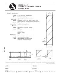
DAMPER SIZE 24 x 24<br />
DAMPER SIZE 12 x 12<br />
FSD-AF-S-<strong>212</strong> - 09-06<br />
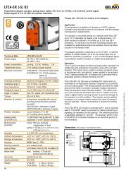
PRESSURE DROP - INCHES OF WATER (In. W.C.)<br />
1.0<br />
.9<br />
.8<br />
.7<br />
.6<br />
.5<br />
.4<br />
.3<br />
.25<br />
.2<br />
.15<br />
.1<br />
.09<br />
.08<br />
.07<br />
.06<br />
.05<br />
.04<br />
.03<br />
.025<br />
.02<br />
.015<br />
.01<br />
100 150 200 300 400 500 700 900 1500 2000 3000 4000 6000<br />
1000<br />
VELOCITY THROUGH FACE AREA<br />
<strong>NCA</strong> MANUFACTURING, INC. 1036 SOUTH JUPITER ROAD GARLAND, TEXAS 75042 TEL. 972-276-5002 FAX 972-276-6747