Submittal - True Round Fire Damper - 1-1/2 Hour - FDD-RD - NCA ...
Submittal - True Round Fire Damper - 1-1/2 Hour - FDD-RD - NCA ...
Submittal - True Round Fire Damper - 1-1/2 Hour - FDD-RD - NCA ...

Create successful ePaper yourself
Turn your PDF publications into a flip-book with our unique Google optimized e-Paper software.
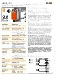
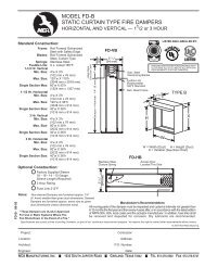
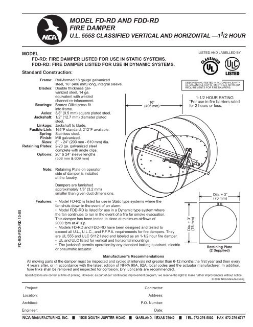
MODEL FD-<strong>RD</strong> AND <strong>FDD</strong>-<strong>RD</strong><br />
FIRE DAMPER<br />
U.L. 555S CLASSIFIED VERTICAL AND HORIZONTAL —1 1 /2 HOUR<br />
MODEL<br />
FD-<strong>RD</strong>: FIRE DAMPER LISTED FOR USE IN STATIC SYSTEMS.<br />
<strong>FDD</strong>-<strong>RD</strong>: FIRE DAMPER LISTED FOR USE IN DYNAMIC SYSTEMS.<br />
Standard Construction:<br />
Frame: Roll-formed 18 gauge galvanized<br />
steel, 16” (406 mm) long, integral sleeve.<br />
Blades: Double thickness galvanized<br />
steel, 14 ga.<br />
equivalent with welded<br />
channel re-inforcement.<br />
Bearings: Bronze Oilite press-fit<br />
into frame.<br />
Axles: 3/8” (9.5 mm) square plated steel.<br />
Jackshaft: 1/2” (12.7 mm) diameter plated<br />
steel.<br />
Linkage: Jackshaft to blade.<br />
Fusible Link: 165°F standard, 212°F available.<br />
Spring: Stainless steel.<br />
Finish: Mill galvanized.<br />
Sizes: 8” - 24” (203 mm - 610 mm) dia.<br />
Retaining Plates: 2-20 ga. galvanized steel<br />
complete with angle clips.<br />
Options: 20” & 24” sleeve lengths<br />
(508 mm & 609 mm)<br />
16”<br />
(406 mm)<br />
LISTED AND LABELLED BY:<br />
DESIGNED AND TESTED IN ACCO<strong>RD</strong>ANCE WITH<br />
UL-555 AND ULC-S112. MEETS ALL NFPA-90A<br />
REQUIREMENTS FOR FIRE DAMPERS.<br />
1-1/2 HOUR RATING<br />
*For use in fire barriers rated<br />
for 2 hours or less.<br />
Note:<br />
Retaining Plate on operator<br />
side of damper is installed<br />
at the facotry.<br />
FD-<strong>RD</strong>-<strong>FDD</strong>-<strong>RD</strong> 10-05<br />
Features:<br />
<strong>Damper</strong>s are furnished<br />
approximately 1/8” (3.2 mm)<br />
smaller than given duct dimensions.<br />
• Model FD-<strong>RD</strong> is listed for use in Static type systems where the<br />
fan shuts down in the event of an alarm.<br />
• Model <strong>FDD</strong>-<strong>RD</strong> is listed for use in a Dynamic type system where<br />
the fan continues to run in the event of a fire for smoke evacuation.<br />
This damper has been tested to close at minimum airflows of<br />
2000 fpm at 4” s.p.<br />
• Models FD-<strong>RD</strong> and <strong>FDD</strong>-<strong>RD</strong> have been designed and tested to<br />
exceed all U.L., U.L.C., and F.F.P.A. requirements for fire dampers. They<br />
are UL 555 and ULC S112 listed and labeled as an 1-1/2 hour fire damper.<br />
• UL and ULC listed for vertical and horizontal mountings.<br />
• The jackshaft permits operation by any standard locking quadrant, electric<br />
or pneumatic actuator.<br />
Retaining Plate<br />
(2 Supplied)<br />
Specifications are correct at time of printing. However, as part of our ‘continuous improvement program,’ we reserve the right to make further improvements without notice.<br />
© 2007 <strong>NCA</strong> Manufacturing<br />
Dia. + 3”<br />
(76 mm)<br />
Dia. + 3”<br />
(76 mm)<br />
Manufacturer’s Recommendations<br />
All moving parts of the damper must be inspected and cycled at intervals not greater than 6-12 months the first year and then every<br />
4 years after, or in accordance with the latest edition of NFPA 90A, 92A, local codes and the actuator manufacturer. In addition,<br />
fuse links shall be removed and inspected for corrosion. Dry lubricants are recommended.<br />
Project:<br />
Location:<br />
Architect:<br />
Engineer:<br />
Contractor:<br />
Address:<br />
P.O. Number:<br />
Date:<br />
<strong>NCA</strong> MANUFACTURING, INC. 1036 SOUTH JUPITER ROAD GARLAND, TEXAS 75042 TEL. 972-276-5002 FAX 972-276-6747
MODEL FD-<strong>RD</strong> AND <strong>FDD</strong>-<strong>RD</strong><br />
FIRE DAMPER<br />
U.L. 555S CLASSIFIED VERTICAL AND HORIZONTAL —1 1 /2 HOUR<br />
© 2005 <strong>NCA</strong> Manufacturing<br />
Pressure drop testing was done by an independent laboratory to the AMCA Standard 500-D, Fig. 5.3<br />
ductwork upstream & downstream.<br />
PRESSURE DROP<br />
PRESSURE DROP (INCHES W.G.)<br />
8” DIAMETER<br />
24” DIAMETER<br />
FACE VELOCITY (FPM)<br />
FD-<strong>RD</strong>-<strong>FDD</strong>-<strong>RD</strong>-02-06<br />
LEAKAGE OBTAINED IN TEST OF 8” DIAMETER AND 24” DIAMETER<br />
WAS LESS THAN 1 CFM/SQ. FT.<br />
<strong>NCA</strong> MANUFACTURING, INC. 1036 SOUTH JUPITER ROAD GARLAND, TEXAS 75042 TEL. 972-276-5002 FAX 972-276-6747