Installation Instructions for Series FD-RD and FDD-RD - NCA ...
Installation Instructions for Series FD-RD and FDD-RD - NCA ...
Installation Instructions for Series FD-RD and FDD-RD - NCA ...

You also want an ePaper? Increase the reach of your titles
YUMPU automatically turns print PDFs into web optimized ePapers that Google loves.
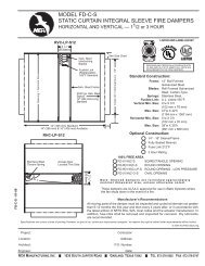
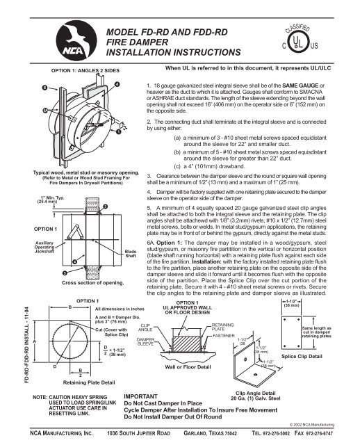
MODEL <strong>FD</strong>-<strong>RD</strong> AND <strong>FD</strong>D-<strong>RD</strong><br />
FIRE DAMPER<br />
INSTALLATION INSTRUCTIONS<br />
C<br />
CLASSIFIED<br />
U L R<br />
US<br />
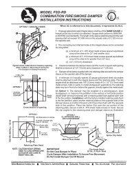
OPTION 1: ANGLES 2 SIDES<br />
When UL is referred to in this document, it represents UL/ULC<br />
8<br />
5A<br />
4<br />
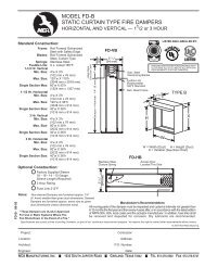
1. 18 gauge galvanized steel integral sleeve shall be of the SAME GAUGE or<br />
heavier as the duct to which it is attached. Gauges shall con<strong>for</strong>m to SMACNA<br />
or ASHRAE duct st<strong>and</strong>ards. The length of the sleeve extending beyond the wall<br />
opening shall not exceed 16” (406 mm) on the operator side or 6” (152 mm) on<br />
the opposite side.<br />
<strong>FD</strong>-<strong>RD</strong>-<strong>FD</strong>D-<strong>RD</strong> INSTALL - 11-04<br />
Typical wood, metal stud or masonry opening.<br />
(Refer to Metal or Wood Stud Framing For<br />
Fire Dampers In Drywall Partitions)<br />
1” Min. Typ.<br />
(25.4 mm)<br />
OPTION 1<br />
Auxiliary<br />
Operating<br />
Jackshaft<br />
A<br />
D<br />
5<br />
4<br />
Cross section of opening.<br />
B<br />
OPTION 1<br />
B<br />
2<br />
3<br />
Cut (Cover with<br />
Splice Clip)<br />
D<br />
2 + 1-1/2”<br />
(38 mm)<br />
Retaining Plate Detail<br />
Blade<br />
Shaft<br />
All dimensions in inches<br />
A <strong>and</strong> B = Damper Dia.<br />
plus 3” (76 mm)<br />
1<br />
CLIP<br />
ANGLE<br />
DAMPER<br />
SLEEVE<br />
2. The connecting duct shall terminate at the integral sleeve <strong>and</strong> is connected<br />
by using either:<br />
(a) a minimum of 3 - #10 sheet metal screws spaced equidistant<br />
around the sleeve <strong>for</strong> 22” <strong>and</strong> smaller duct.<br />
(b) a minimum of 5 - #10 sheet metal screws spaced equisdistant<br />
around the sleeve <strong>for</strong> greater than 22” duct.<br />
(c) a 4” (101mm) drawb<strong>and</strong>.<br />
3. Clearance between the damper sleeve <strong>and</strong> the round or square wall opening<br />
shall be a minimum of 1/2” (13 mm) <strong>and</strong> a maximum of 1” (25 mm).<br />
4. Damper will be factory supplied with one retaining plate secured to the damper<br />
sleeve on the operator side of the damper.<br />
5. A minimum of 4 equally spaced 20 gauge galvanized steel clip angles<br />
shall be attached to both the integral sleeve <strong>and</strong> the retaining plate. The clip<br />
angles shall be attachewd with 1/8” (3.2mm) rivets, #10 x 1/2” (12.7mm) steel<br />
metal screws, bolts or welds. In metal stud/gypsum applications, the retaining<br />
plate may be in front of or behind the gypsum, directly against the metal studs.<br />
6A. Option 1: The damper may be installed in a wood/gypsum, steel<br />
stud/gypsum, or masonry fire partitition in the vertical or horizontal position<br />
(blade shaft running horizontal) with a retaining plate flush against each side<br />
of the fire partition. <strong>Installation</strong>: with the factory installed retaining plate flush<br />
to the fire partition, place another retaining plate on the opposite side of the<br />
damper sleeve <strong>and</strong> slide it <strong>for</strong>ward until it becomes flush with the opposite<br />
side of the partition. Place the Splice Clip over the cut portion of the<br />
retaining plate. Secure it with 4 - #10 sheet metal screws or rivets. Secure<br />
the clip angles to the retaining plate <strong>and</strong> damper sleeve as illustrated.<br />
OPTION 1<br />
UL APPROVED WALL<br />
OR FLOOR DESIGN<br />
Wall or Floor Detail<br />
RETAINING<br />
PLATE<br />
FASTENER<br />
1-1/2”<br />
(38<br />
1-1/2”<br />
(38 mm)<br />
1-1/2”<br />
(38 mm)<br />
1-1/2”<br />
(38 mm)<br />
Same length as<br />
cut in damper/<br />
retaining plates<br />
Splice Clip Detail<br />
NOTE: CAUTION HEAVY SPRING<br />
USED TO LOAD SPRING/LINK<br />
ACTUATOR USE CARE IN<br />
RESETTING LINK.<br />
Clip Angle Detail<br />
IMPORTANT<br />
20 Ga. (1) Galv. Steel<br />
Do Not Cast Damper In Place<br />
Cycle Damper After <strong>Installation</strong> To Insure Free Movement<br />
Do Not Install Damper Out Of Round<br />
© 2002 <strong>NCA</strong> Manufacturing<br />
<strong>NCA</strong> MANUFACTURING, INC. 1036 SOUTH JUPITER ROAD GARLAND, TEXAS 75042 TEL. 972-276-5002 FAX 972-276-6747
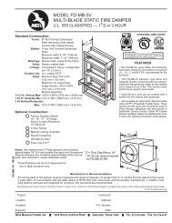
MODEL <strong>FD</strong>-<strong>RD</strong> AND <strong>FD</strong>D-<strong>RD</strong><br />
FIRE DAMPER<br />
INSTALLATION INSTRUCTIONS<br />
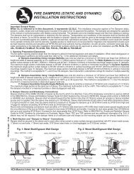
6B. Option 2: The damper may also be installed in a steel stud/gypsum,<br />
or masonry wall, in a vertical position (blade running horizontal), with a<br />
retaining plate on one side of the wall. <strong>Installation</strong>: with the factory installed<br />
retaining plate flush to the fire wall, place 8 screws (#10 sheet metal <strong>for</strong><br />
steel studs long enough to penetrate the metal stud by 1/2” minimum or<br />
#10 x 1-1/4” masonry screws) equidistant around the perimeter of the<br />
retaining plate. Screws are placed in each corner <strong>and</strong> halfway between the<br />
corners as shown.<br />
7. Electrical <strong>and</strong>/or pneumatic connections to damper actuators (if applicable)<br />
should be made in accordance with wiring <strong>and</strong> piping diagrams developed<br />
in compliance with applicable codes, ordinances <strong>and</strong> regulations.<br />
8. Refer to the installation instruction <strong>for</strong> Drywall Type Construction <strong>for</strong> the<br />
material <strong>and</strong> opening framing details.<br />
8<br />
OPTION 2: ANGLE 1 SIDE<br />
4<br />
OPTION 2<br />
Retaining Plate Detail<br />
OPTION 2<br />
STEEL STUD OR MASONRY<br />
WALL UL DESIGN<br />
Cutline on<br />
retaining<br />
plate<br />
(Cover with<br />
Splice Cap)<br />
FASTENER<br />
5<br />
RETAINING<br />
PLATE<br />
1<br />
CLIP ANGLE<br />
FASTENER<br />
DAMPER<br />
SLEEVE<br />
6B<br />
1-1/2”<br />
(38 mm)<br />
Wall Detail<br />
<strong>FD</strong>-<strong>RD</strong>-<strong>FD</strong>D-<strong>RD</strong> INSTALL - 11-04<br />
Typical masonry or metal stud opening.<br />
(Refer to Metal Stud Framing For<br />
Fire Dampers In Drywall Partitions)<br />
1” Min. Typ.<br />
(25.4 mm)<br />
OPTION 2<br />
Auxiliary<br />
Operating<br />
Jackshaft<br />
5<br />
6B<br />
4<br />
Cross section of opening.<br />
3<br />
Blade<br />
Shaft<br />
Same length as<br />
cut in damper/<br />
retaining plates<br />
Splice Clip Detail<br />
1-1/2”<br />
(38 mm)<br />
1-1/2”<br />
(38 mm)<br />
1-1/2”<br />
(38 mm)<br />
Clip Angle Detail<br />
20 Ga. (1) Galv. Steel<br />
Manufacturer’s Recommendations<br />
All moving parts of the damper must be inspected <strong>and</strong> cycled at intervals not greater than every six months <strong>and</strong> in accordance with<br />
the latest edition of NFPA 90A, 92A, local codes <strong>and</strong> the actuator manufacturer. In addition, fuse links shall be removed <strong>and</strong> inspected<br />
<strong>for</strong> corrosion. Dry lubricants are recommended.<br />
This installation sheet has been reviewed <strong>and</strong> accepted by Underwriters Laboratories.<br />
When UL is referred to in this document, it represents UL/ULC. © 2002 <strong>NCA</strong> Manufacturing<br />
<strong>NCA</strong> MANUFACTURING, INC. 1036 SOUTH JUPITER ROAD GARLAND, TEXAS 75042 TEL. 972-276-5002 FAX 972-276-6747