Wilo Top S Wet Rotor Circulation Pumps - Wilo Canada Inc.
Wilo Top S Wet Rotor Circulation Pumps - Wilo Canada Inc.
Wilo Top S Wet Rotor Circulation Pumps - Wilo Canada Inc.

You also want an ePaper? Increase the reach of your titles
YUMPU automatically turns print PDFs into web optimized ePapers that Google loves.
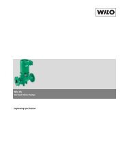
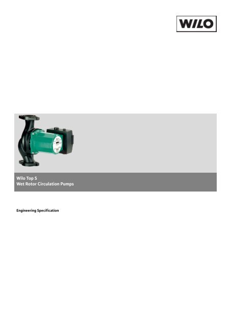
<strong>Wilo</strong> <strong>Top</strong> S<br />
<strong>Wet</strong> <strong>Rotor</strong> <strong>Circulation</strong> <strong>Pumps</strong><br />
Engineering Specification
PART 1 - GENERAL<br />
1.1 SUMMARY<br />
A. Furnish and install circulating pumps consistent with the hydronic system’s performance and requirements. The<br />
circulating pumps shall be suitable for the specified system function and capacity.<br />
1.2 REGULATORY<br />
A. Circulating pumps shall be rated to a minimum 125 PSI and 212 degrees Fahrenheit and where applicable, bear the<br />
approval symbol of the required regulatory body.<br />
B. Electrical assemblies (circuitry, wiring terminals and internal connections) of the circulating pumps shall be certified and<br />
registered to bear the emblem of UL, CSA or ETL as required. Electrical assembly shall meet codes and standards<br />
established by national bodies.<br />
1.3 REFERENCES<br />
A. UL 778 Standard<br />
1.4 SUBMITTALS<br />
A. Provide submittals, warranty information and shop drawings in accordance with the General Requirements and as<br />
specified herein. Submit detailed product drawings including wiring schematics. Indicate critical dimensions of the<br />
circulating pumps.<br />
B. Submit manufacturer’s technical data in the form of published Installation and Operation and Maintenance Manuals to<br />
be supplied with the circulating pumps at time of installation.<br />
C. Circulating pumps shall be tested and verified for performance. Copies of “Certification of Performance” shall be made<br />
available to the specifying engineer if requested.<br />
D. Submit catalogue data on all equipment, pipe, fittings, fasteners and associated items supplied by others to complete<br />
the installation of the circulating pumps in the system installation.<br />
1.5 DELIVERY, STORAGE AND HANDLING<br />
A. Circulating pumps shipped in boxes and are to remain in factory shipping condition until immediately prior to<br />
installation.<br />
B. Circulating pumps are to be stored indoors in a conditioned space, protected from exposure to the elements, and from<br />
exposure to other potential contaminants.<br />
C. Factory applied labels are to remain in place and un-obscured. These identification tags are to display model numbers,<br />
serial numbers, and evidence of certifications/listings.<br />
2<br />
WIL-SPC-TOPS001-07-11
1.6 WARRANTY<br />
A. The Manufacturer shall warrant the circulating pumps for a period of 2 years from date of manufacture or 1.5 years<br />
from the date of installation, subject to the Terms and Conditions of said Warranty. A copy of the Manufacturer’s<br />
Warranty shall be provided as part of the Submittals as outlined in Section 1.04 of this specification.<br />
PART 2 - PRODUCTS<br />
2.1 TERMINAL BOXES<br />
A. The circulating pumps shall have a high quality cast aluminum terminal box with NPT electrical connections and a<br />
secure, gasketed cover, Class 2 protection level.<br />
2.2 ELECTRICAL CONNECTIONS<br />
A. Circulating pump shall have a coded terminal strip indicating common/neutral/ground within the terminal box for field<br />
connections for single phase and L1, L2, L3 plus ground for three phase.<br />
2.3 ELECTRICAL<br />
A. All 24 volt wiring shall be of 18 gauge or larger, UL/CSA approved, 300 volts, 220 deg F maximum temperature.<br />
B. All 110 volt wiring shall be of 14 gauge or larger, UL/CSA approved, 300 volts, 220 deg F maximum temperature.<br />
C. The motor shall be a minimum of class H winding insulation as defined by UL 778.<br />
D. Voltage variances shall be less than +/- 5% from rated voltage with pump under load conditions. Amperage variance<br />
between phases on three phase systems shall be less than +/- 5%. Power to the pump is confirmed with a green light<br />
in the pump electrical terminal box. Rotation on three phase systems is reverse if red light appears in the pump<br />
electrical box (no red light is correct rotation).<br />
E. Stator thermal overload sensors are provided as an integral part of the pump and are potential-free, normally closed<br />
contact (maximum load 250 volt/1 amp). The thermal sensor shall be wired to the contactor via terminals P1 and P2. In<br />
the event of winding temperatures in excess of 375 deg F (190 deg C), the thermal sensor beaks contact to the relay<br />
(supplied by others) turning the power off to the pump until the overload has cooled down. If the thermal overload<br />
sensor system is not used the pump must be protected against overloading by the use of motor starter heaters. The<br />
heater set point is based on the model and speed as indicated on the nameplate of the pump. Single phase systems will<br />
incorporate circuit breakers to protect the pump against overload conditions.<br />
2.4 CONTROL, OPERATION AND DIAGNOSTICS<br />
A. Circulating pumps must be capable of multi-speed operation, manually changed in the terminal box after power to<br />
the pump has been discontinued.<br />
B. Single phase models shall have an LED indicating power is available at the terminal strip. Additionally, three phase<br />
models shall have a warning LED indicating the circulator is running in reverse rotation and that field wiring<br />
connections should be reviewed and corrected.<br />
C. A winding resistance chart shall be accessible for service and diagnostics as required.<br />
D. The circulating pumps shall be suitable for inclusion as part of a DDC or Building Management System as required<br />
under Division 23 Controls.<br />
3<br />
WIL-SPC-TOPS001-07-11
2.5 MATERIALS AND CONSTRUCTION<br />
A. Circulating pumps shall be constructed with either bronze or Cast-Iron bodies. Cast Iron body circulating pumps<br />
shall have a factory applied Catephoresic coating.<br />
B. Shafts shall be constructed of high quality stainless steel. Motor bearings shall be metal impregnated carbon.<br />
Impellers will be constructed of a high strength, glass filled polypropylene engineered composite.<br />
PART 3 EXECUTION<br />
3.1 PREPARATION<br />
A. Prior to commencing work the contractor will have read and understood both the Installation, and Operation and<br />
Maintenance Manuals (IOM) supplied and enclosed with the attendant circulating pumps. These are to be supplied in<br />
English, French and Spanish.<br />
B. The effectiveness of the system is dependant on the system being designed and installed correctly. Proper<br />
consideration of factors such as BTU loads, outdoor design temperature, indoor design temperature, room set-point<br />
temperature(s), differential fluid temperatures, head loss, flow rates and transfer capacities of the heat emitters is<br />
critical.<br />
C. Prior to final connection of the circulators as part of the hydronic system, the system piping shall be flushed of all<br />
contaminants and foreign objects.<br />
3.2 INSTALLATION<br />
A. The circulating pumps must be installed by a qualified installer/service technician.<br />
B. The circulating pumps shall be installed in accordance with the relevant requirements of the Local Authority<br />
HavingJurisdiction, as required to meet the performance requirements and function specified for the system.<br />
C. The circulating pumps must be installed and operated strictly in accordance with the terms set out in both the<br />
Installation and Operation and Maintenance Manuals supplied and enclosed with the attendant circulating pumps.<br />
D. The pump shall be installed with the motor shaft in a horizontal plane with no exceptions. The electrical terminal box<br />
shall be installed at the 3:00, 9:00 or 12:00 position, referenced from the nameplate end of the motor.<br />
E. The pump must be installed in a way that it is not stressed by the pipework. A minimum of three pipe diameters is<br />
recommended on the inlet of the pump. Pressure gauges are recommended, installed in the ¼” NPT suction and<br />
discharge pressure gauge tappings provided with the pump.<br />
F. Where antifreeze protection is required, the maximum concentration of heating system glycol is 50% by volume. High<br />
concentrations of glycol at lower system design temperatures may require increasing the design operating point. Use<br />
of leak sealant products or automotive antifreeze is not permitted.<br />
G. Fluid temperature limitations are 248 deg F (120 deg C) to 14 deg F (-10 deg C) for closed systems and 140 deg F (60<br />
deg C) to 14 deg F (-10 deg C) for open systems. Maximum ambient temperature surrounding the pump shall be<br />
between 32 deg F (0 deg C) to 104 deg F (40 deg C).<br />
H. Inlet pressure shall not exceed 145 psi (10 Bar). Minimum inlet pressure shall be enough<br />
3.3 FIELD QUALITY CONTROL<br />
A. Upon receipt and prior to commissioning the circulating pumps should be inspected for any sign of visible damage.<br />
B. Prior to commissioning the circulating pumps, the system connections should be complete and leak free. The system<br />
should be filled and purged as per instructions in the IOM manuals. The system fluid should be tested and have a pH<br />
level of between 8 and 9.5 and be suitable for hydronic system use.<br />
C. Following fill and purge, the system should undergo a pressure test, followed by a run-through of the sequence of<br />
operations listed in the IOM manuals.<br />
4<br />
WIL-SPC-TOPS001-07-11
Mark Qty. Duty Inlet<br />
design<br />
temp<br />
P-1 1 Primary loop<br />
pump<br />
P-2 1 Secondary loop<br />
terminal units<br />
P-3-5 3 Radiant loop<br />
manifold supply<br />
P-6 1 Snow Melt<br />
manifold supply<br />
Outlet<br />
design<br />
temp<br />
Typical Schedule:<br />
Manufacturer Model Electrical<br />
Service<br />
required<br />
180°F 160°F WILO TOP S 1.5 X<br />
35<br />
230/1/60,<br />
20 Amp<br />
required<br />
180°F 160°F WILO STAR S 21 115/1/60,<br />
15 Amp<br />
required<br />
130°F 110°F WILO STAR S 16 115/1/60,<br />
15 Amp<br />
required<br />
160°F 110°F WILO TOP S 1.25 x<br />
25<br />
115/1/60,<br />
15 Amp<br />
required<br />
Pump<br />
function<br />
Primary<br />
circulation<br />
Zone<br />
control to<br />
panel<br />
radiators<br />
Zone<br />
control to<br />
radiant<br />
panels<br />
Zone<br />
control to<br />
snowmelt<br />
panels<br />
Remarks<br />
Two speed<br />
Module with<br />
3 hi temp<br />
zones and a<br />
pressure<br />
bypass<br />
Radiant zone<br />
control<br />
panel, each<br />
to have 5<br />
zones low<br />
temp, 20<br />
MBH output<br />
Snow melt<br />
system with<br />
ECL 302<br />
snowmelt<br />
control and<br />
snow sensor.<br />
140 MBH<br />
Output<br />
capacity<br />
<strong>Wilo</strong> USA LLC<br />
1290 N 25th Ave<br />
Melrose Park, IL 60160<br />
Tel: 866-945-6872<br />
Fax: 708-338-9455<br />
Email: info@wilo-usa.com<br />
Web: www.wilo-usa.com<br />
<strong>Wilo</strong> <strong>Canada</strong> <strong>Inc</strong>.<br />
Bay 7-2915 10th Ave NE<br />
Calgary, AB T2A 5L4<br />
Tel: 866-945-6236<br />
Fax: 403-277-9456<br />
Email: info@wilo-canada.com<br />
Web: www.wilo-canada.com<br />
<strong>Wilo</strong> Mexico<br />
Managua No 978, Colonia Lindavista<br />
07300 México, D.F., México<br />
Tel: + 52 55 5586 3209<br />
Fax: + 52 55 5586 3209<br />
Email: info@wilo.com.mx<br />
Web: www.wilo-mexico.com<br />
5<br />
WIL-SPC-TOPS001-07-11