Wilo NL Base Mount End Suction Pumps - Wilo Canada Inc.
Wilo NL Base Mount End Suction Pumps - Wilo Canada Inc.
Wilo NL Base Mount End Suction Pumps - Wilo Canada Inc.

You also want an ePaper? Increase the reach of your titles
YUMPU automatically turns print PDFs into web optimized ePapers that Google loves.
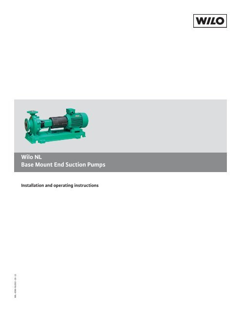
<strong>Wilo</strong> <strong>NL</strong><strong>Base</strong> <strong>Mount</strong> <strong>End</strong> <strong>Suction</strong> <strong>Pumps</strong>Installation and operating instructionsWIL-IOM-<strong>NL</strong>002-10-11
1 General1.1 DescriptionThe <strong>NL</strong> (<strong>End</strong> <strong>Suction</strong>) Series centrifugal pumps are framemounted pumps which feature – high efficiency, ruggedconstruction, compact design, foot mounted volute, centerdrop out coupler, and non-regreasable bearings. Thesefeatures, make installation, operation, and service easy toperform.1.2 Pump ApplicationThe standard <strong>NL</strong> (<strong>End</strong> <strong>Suction</strong>) Series centrifugal pump’sbronze fitted construction makes it ideal for service in thefollowing applications: unheated domestic and fresh water,boiler feed water, condensate, hydronic cooling or heating,pressure boosting, general pumping and benign liquids.For other applications contact your local <strong>Wilo</strong> representative.2 Safety InstructionsSafety InstructionsThis safety alert symbol will be used in this manual andon the pump safety instruction decals to draw attentionto safety related instructions. When used the safetyalert symbol means ATTENTION! BECOME ALERT! YOURSAFETY IS INVOLVED! FAILURE TO FOLLOW THE IN-STRUCTIONS MAY RESULT IN A SAFETY HAZARD.2.1 Instruction DecalsYour <strong>NL</strong> (<strong>End</strong> <strong>Suction</strong>) Series pump should have the followingsafety instruction decals displayed. If the decals aremissing or illegible contact your local <strong>Wilo</strong> representative fora replacement.1.3 Operational LimitsUnless special provisions have been made for your pump by<strong>Wilo</strong>, the operational limits for <strong>NL</strong> (<strong>End</strong> <strong>Suction</strong>) Series<strong>Pumps</strong> are as follows:Maximum Working Pressure,Listed on pump nameplate.175 psi (12 bar) standard250 psi (17 bar) available upon request1.4 Seal Operating LimitsStandard Mechanical SealsPH Limitations 7-11Temperature Range 0 to +250°F [-20 to +120°C]For use on closed or open systems which are relatively freeof dirt and/or other abrasive particles.1.5 Pump Identification<strong>Wilo</strong> pumps are designated by a series of numbers suchas <strong>NL</strong> (<strong>End</strong> <strong>Suction</strong> Series). The pump nameplate givesidentification and rating information as identified in Figure1. Permanent records for this pump are kept by the serialnumber and therefore must be used with all correspondenceand spare parts orders.Figure 2 - Decals2.2 Additional Safety Requirements• Electrical connections to be made by qualified Electricianin accordance with all national, state and local codes.• Motor must have properly sized starter with properlysized heaters to provide overload and under-voltageprotection.• If pump, motor or piping are operating at extremely highor low temperatures, guarding or insulation is required.• The maximum working pressure of the pump is listed onthe pump nameplate, do not exceed this pressure.2.3 Electrical SafetyWARNING: Electrical Shock HazardImminently Hazardous Situation!Electrical connections to be made by a qualified electricianin accordance with all applicable codes, ordinances,and good practices. Failure to follow these instructionscould result in serious personal injury or death, or propertydamage.Figure 1 - Nameplate2 WIL-IOM-<strong>NL</strong>002-10-11
WARNING: Electrical Overload HazardImminently Hazardous Situation!Three phase motors must have properly sized heatersto provide overload and undervoltage protection. Singlephase motors have built-in overload protectors. Failureto follow these instructions could result in serious personalinjury or death, or property damage.2.4 Thermal SafetyWARNING: Falling Objects HazardImminently Hazardous Situation!Eyebolts or lifting lugs, if provided, are for lifting only thecomponents to which they are attached. Failure to followthese instructions could result in serious personal injuryor death, or property damage.If lifting base pump is required, use a nylon string, chain, or wire rope, hitcharound bearing bracket and the casing. If lifting of the entire pump unit isrequired, do so with slings placed under the base rails as shown.WARNING: Extreme Temperature HazardImminently Hazardous Situation!If pump, motor, or piping are operating at extremely highor low temperatures, guarding or insulation is required.Failure to follow these instructions could result inseriouspersonal injury or death, or property damage.2.5 Mechanical SafetyWARNING: Unexpected Startup HazardImminently Hazardous Situation!If pump, motor, or piping are operating at extremely highor low temperatures, guarding or insulation is required.Failure to follow these instructions could result inseriouspersonal injury or death, or property damage.WARNING: Excessive System Pressure HazardImminently Hazardous Situation!The maximum working pressure of the pump is listed onthe nameplate, do not exceed this pressure. Do not use airto hydrotest pump. Failure to follow these instructionscould result in serious personal injury or death, or propertydamage.WARNING: Excessive Pressure Hazard - VolumetricExpansionImminently Hazardous Situation!The heating of water and other fluids causes volumetricexpansion. The associated forces may cause failure ofsystem components and release of high temperaturefluids. This will be prevented by installing properly sizedand located compression tanks and pressure relief valves.Failure to follow these instructions could result in seriouspersonal injury or death, or property damage.3 Pump LocationLocate the pump so there is sufficient room for inspection, maintenance andservice. If the use of a hoist or tackle is needed, allow ample head room.Figure 3 - Lifting UnitThe best pump location for sound and vibration absorption is on a concretefloor with subsoil underneath. If the pump location is overhead, specialprecautions should be undertaken to reduce possible sound transmission.Consult a sound specialist.If the pump is not on a closed system, it should be placed as near as possibleto the source of the liquid supply, and located to permit installation with thefewest number of bends or elbows in the suction pipe.The installation must be evaluated to determine that the Net Positive<strong>Suction</strong> Head Available (NPSHA) meets or exceeds the Net Positive <strong>Suction</strong>Head Required (NPSHR), as stated by the pump performance curve.IMPORTANT: Do not install and operate <strong>Wilo</strong> <strong>Pumps</strong>, Triple Duty (3-D)Valves, <strong>Suction</strong> Diffusers, etc., in closed systems unless the system isconstructed with properly sized safety devices and control devices. Suchdevices include the use of properly sized and located pressure relief valves,compression tanks, pressure controls, temperature controls, and flow controlsas appropriate. If the system does not include these devices, consultthe responsible engineer or architect before making pumps operational.4 Purpose of ManualThis manual is furnished to acquaint you with some of the practical ways toinstall, operate, and maintain this pump. Read it completely before doingany work on your unit and keep it handy for future reference. Equipment<strong>Wilo</strong> <strong>NL</strong> - Installation and Operation Manual3
cannot operate well without proper care. To keep this unit at top efficiency,Follow the recommended installation and servicing procedures outlined inthis manual.5 WarrantyShould your pump ever need servicing, please contact <strong>Wilo</strong> at 1-866-WILO-USA.6 Pump IdentificationThe pump should be installed with sufficient accessibility for inspection andmaintenance. A clear space with ample head room should be allowed for theuse of an overhead crane or hoist sufficiently strong to lift the unit.NOTE: Allow sufficient space to be able to dismantle pump without disturbingthe pump inlet and discharge piping.Select a dry place above the floor level wherever possible. Take care to preventpump from freezing during cold weather when not in operation. Shouldthe possibility of freezing exist during a shut-down period, the pump shouldbe completely drained, and all passages and pockets where liquid mightcollect should be blown out with compressed air. Make sure there is a suitablepower source available for the pump driver. If motor driven, electricalcharacteristics should be identical to those shown on motor data plate.All pumps are designated by Serial Number, Pump Series, and Size. Thisinformation is stamped on an identification plate which is mounted on thepump. Refer to pump identification in specific instruction section of thismanual for detailed information.7 Receiving PumpCheck pump for shortages and damage immediately upon arrival. (An absolutemust.) Prompt reporting to the carrier’s agent with notations made onthe freight bill, will expedite satisfactory adjustment by the carrier.<strong>Pumps</strong> and drivers normally are shipped from the factory mounted andpainted with single coat of primer and two finish coats. Couplings may beeither completely assembled or have the coupling hubs mounted on theshafts and the connecting members removed. When the connecting membersare removed, they will be packaged in a separate container and shippedwith the pump or attached to the base plate.Shafts are in alignment when the unit is shipped; however, due to shipping,the pumps may arrive misaligned and, therefore, alignment must beestablished during installation. <strong>Wilo</strong> has determined that proper and correctalignment can only be made by accepted installation practices. Refer to thefollowing paragraphs on “FOUNDATION”, “BASE PLATE SETTING”, “GROUT-ING PROCEDURE” and “ALIGNMENT PROCEDURE”.10 FoundationThe foundation for your pump must be sufficiently rigid to absorb anyvibration and stress encountered during pump operation. A raised foundationof concrete is preferable for most floor mounted pumps. The raisedfoundation assures a satisfactory base, protects against flooding, simplifiesmoisture drainage, and facilitates keeping the area clean.The foundation should be poured without interruption to within 1/2 [13mm]to 1-1/2 inches [38mm] of the finished height. The top surface of thefoundation should be well scored and grooved before the concrete sets; thisprovides a bonding surface for the grout.Foundation bolts should be set in concrete as shown in Figure 4. An optional4 inch [102mm] long tube around the bolts at the top of the concretewill allow some flexibility in bolt alignment to match the holes in the baseplate. Allow enough bolt length for grout, shims, lower base plate flange,nuts and washers. The foundation should be allowed to cure for several daysbefore the base plate is shimmed and grouted.8 Temporary StorageIf the pump is not to be installed and operated soon after arrival, store it ina clean, dry place having slow, moderate changes in ambient temperature.Rotate the shaft periodically to coat the bearings with lubricant and toretard oxidation, corrosion, and to reduce the possibility of false brinellingof the bearings.9 LocationFigure 4 - FoundationThe pump should be installed as near the suction supply as possible, but noless than five suction diameters with the shortest and most direct suctionpipe practical. The total dynamic suction lift (static lift plus friction losses insuction line) should not exceed the limits for which the pump was sold.The pump must be primed before starting. Whenever possible, the pumpshould be located below the fluid level to facilitate priming and assure asteady flow of liquid. This condition provides a positive suction head onthe pump. It is also possible to prime the pump by pressurizing the suctionvessel.When installing the pump, consider its relative location in relation to thesystem to assure that sufficient Net Positive <strong>Suction</strong> Head (NPSH) at pumpsuction is provided. Available NPSH (NPSHA) must always equal or exceedthe required NPSH (NPSHR) of the pump.11 <strong>Base</strong> Plate Setting (Before Piping)NOTE: This procedure assumes that a concrete foundation has been preparedwith anchor or hold down bolts extending up ready to receive unit. Itmust be understood that pump and motor have been mounted and roughaligned at the factory. If the motor is to be field mounted, consult factoryfor recommendations. <strong>Wilo</strong> cannot assume responsibility for final alignment.4 WIL-IOM-<strong>NL</strong>002-10-11
• Use blocks and shims under base for support at anchorbolts and midway between bolts, to position base approximately1” [25mm] above the concrete foundation,with studs extending through holes in the base plate.• By adding or removing shims under the base, level andplumb the pump shaft and flanges. The base plate doesnot have to be level.• Draw anchor nuts tight against base, and observe pumpand motor shafts or coupling hubs for alignment. (Temporarilyremove coupling guard for checking alignment.)• If alignment needs improvement, add shims or wedges atappropriate positions under base, so that retightening ofanchor nuts will shift shafts into closer alignment. Repeatthis procedure until a reasonable alignment is reached.• NOTE: Reasonable alignment is defined as that which ismutually agreed upon by pump contractor and the acceptingfacility (final operator). Final alignment proceduresare covered under “Alignment Procedures.”• Check to make sure the piping can be aligned to the pumpflanges without placing pipe strain on either flange.• Grout in base plate completely (See “Grouting Procedure”)and allow grout to dry thoroughly before attachingpiping to pump. (24 hours is sufficient time with approvedgrouting procedure.)12 Grouting ProcedureGrout compensates for uneven foundation, distributes weight of unit, andprevents shifting. Use an approved, non-shrinking grout, after setting andleveling unit (See figure 5).13 Coupling Guard Removal / InstallationWARNING: Unexpected Start-Up HazzardImminently Hazardous Situation!Disconnect and lock out power before servicing. Failureto follow these instructions could result in serious personalinjury or death and property damage.13.1 Removal• Remove the screws, clips, and washers holding the couplerguard halves together.• Remove the upper and lower coupler guard halves fromthe coupler guard support plate assembled to the driveend (inboard) of the pump.13.2 Installation• Check coupler alignment before proceeding. Correct ifnecessary.• Attach the upper and lower coupler guard halves onto thegroove in the coupler guard support plate• Attach the existing screws and washers to the uppercoupler guard half.• Attach the clip onto the lower coupler guard half.• Fasten coupler guard hardware, see Figure 6.• Build strong form around the foundation to contain grout.• Soak top of concrete foundation thoroughly, then removesurface water.• <strong>Base</strong> plate should be completely filled with grout.• After the grout has thoroughly hardened, check the foundationbolts and tighten if necessary.• Check the alignment after the foundation bolts aretightened.• Approximately 14 days after the grout has been pouredor when the grout has thoroughly dried, apply an oil basepaint to the exposed edges of the grout to prevent air andmoisture from coming in contact with the grout.Figure 6 - Coupler Guard Installation13.2 Replacement of Coupler GuardFigure 5 - Setting <strong>Base</strong> Plate and Grouting• New replacement coupler halves will be longer than theexisting ones.• Check the required guard length from the coupler guardsupport plate to the motor face.• Mark the length on the guard halves.• Cut the guard halves at the grooves.• Check coupler alignment before proceeding. Correct ifnecessary.• Attach the upper and lower coupler guard halves onto thegrove in the coupler guard support plate.• Attach the existing screws and washers to the uppercoupler guard half.• Attach the clip onto the lower coupler guard half.• Fasten coupler guard hardware.<strong>Wilo</strong> <strong>NL</strong> - Installation and Operation Manual5
14 Alignment ProcedureNOTE: A ‘flexible coupling’ will only compensate for small amounts of misalignment.Permissible misalignment will vary with the make of coupling.Consult coupling manufacturer’s data for specific tolerances.Allowances are to be made for thermal expansion during cold alignment,so that the coupling will be aligned at operating temperature. In all cases,a coupling must be in alignment for continuous operation. Even though thecoupling may be lubricated, misalignment causes excessive wear, vibration,and bearing loads that result in premature bearing failure and ultimate seizingof the pump. Misalignment can be angular, parallel, or a combination ofthese, and in the horizontal and vertical planes. Final alignment should bemade by moving and shimming the pump or motor on the base plate, untilthe coupling hubs are within the recommended tolerances measured in totalrun-out. All measurements should be taken with the pump and motor footbolts tightened. The shaft of sleeve bearing motors should be in the centerof its mechanical float.To check parallel alignment:• A straight edge should be held against the edges of thecoupling halves at any four places 90° apart around thecoupling.• The straight edge should be parallel to the pump anddriver shafts at all times.• Insert shims until the straight edge lies flat against bothcoupling halves at all four checkpoints.• The pump and driver will then be in proper parallel alignment.NOTE: Proper alignment is essential for correct pump operation. This shouldbe performed after base plate has been properly set and grout has driedthoroughly according to instructions. Final alignment should be made byshimming driver only. Alignment should be made at operating temperatures.WARNING: Unexpected Start-up HazardImminently Hazardous Situation!Disconnect and lock out power before servicing. Failureto follow these instructions could result in serious personalinjury or death and property damage.14.1 Initial Alignment of the Flexible Coupling (See figure 7)The pump and driver were accurately aligned at the factory. However, it isimpossible to maintain this alignment during shipping and handling. Thereforeit will be necessary for you to realign the pump and driver. Flexible couplingsare not universal joints. They should not be used to compensate formisalignment of the pump and motor shafts. Their function is to transmitpower from the driver to the pump while compensating for thermal expansionand shaft end movement. The coupling faces should be far enoughapart so that they do not make contact when the motor shaft is forced tothe limit of the bearing clearance toward the pump shaft.In order to properly align the coupling, you will need a taper gauge or set offeeler gauges, and a straight edge.There are two types of misalignment encountered with flexible couplings:angular misalignment, in which the shafts are not parallel, and parallel misalignmentwhere the shafts are parallel but not on the same axis.To check angular alignment:• Insert a feeler gauge or taper gage at any four places 90°apart around the coupling halves.• Insert shims under the driver feet until the same readingis obtained at all four check points.• The pump and driver will then be in angular alignment.Figure 7 - Checking Alignment (Straight Edge Method)14.2 For Fine Aignment, 3500 RPM OPERATION, For OtherCoupler Types (See figure 8)A dial indicator should be used when greater alignment accuracy is required.Use the following alignment tolerances unless specified otherwise by thecoupling manufacturer. On sleeve type couplings make sure there is atleast 1/8 inch [3mm] end clearance between the sleeve and the two couplinghalves.To check angular misalignment:• <strong>Mount</strong> the dial indicator base to the coupling half, andposition the dial indicator button on the front or rear faceof the opposite coupling half.• Set the dial to zero, rotate both coupling halves together,making sure the indicator• button always indicates off the same spot.• Misalignment values within 0.004 inches [.10mm] TIR perinch [25mm] of coupler radius is permissible.To check parallel misalignment:• <strong>Mount</strong> the dial indicator base to one coupling half, orshaft and position the dial indicator button on the outsidediameter of the opposite coupling half.• Set the dial to zero, rotate both coupling halves together,making sure the indicator button always indicates off thesame spot.• Misalignment within 0.004 inches [.10mm] TIR is permissible.6 WIL-IOM-<strong>NL</strong>002-10-11
Figure 8 - Checking Alignment (Dial Indicator Method)NOTE: Final alignment cannot be accomplished until the pump has been operatedinitially for a sufficient length of time to attain operating temperature.When normal operating temperature has been attained, secure thepump to re-check alignment and compensate for temperature accordingly.WARNING: Rotating Components HazardImminently Hazardous Situation!Do not operate pump without all guards in place. Failureto follow these instructions could result in serious personalinjury or death and property damage.15 <strong>Suction</strong> and Discharge Piping General PrecautionsFigure 9 - Installation of Eccentric Tapered Reducers15.3 Discharge Piping Precautions and RecommendationsDischarge piping should also be short and direct as possible, with few elbowsand fittings, to reduce head loss from friction.The discharge pipe diameter should be the same as, or larger than, thedischarge nozzle diameter.15.4 Valves in Discharge Piping Precautions and RecommendationsThe discharge piping should include a check valve and a gate valve. Thecheck valve should be located between the gate valve and the pump. If anincreaser is used in the discharge piping, the increaser should be installedbetween the pump nozzle and the check valve. The check valve protectsagainst a reverse flow of the liquid if the driver fails. (See Figure 10).When installing the pump piping, be sure to observe the followingprecautions:• Piping should always be run to the pump. Do not movepump to pipe. This could make final alignment impossible.• Both the suction and discharge piping should be supportedindependently near the pump and properlyaligned, so that no strain is transmitted to the pump whenthe flange bolts are tightened. Use pipe hangers or othersupports at necessary intervals to provide support. Whenexpansion joints are used in the piping system, they mustbe installed beyond the piping supports closest to thepump. Tie bolts should be used with expansion joints toprevent pipe strain. Do not install expansion joints nextto the pump or in any way that would cause a strain onthe pump resulting from system pressure changes. It isusually advisable to increase the size of both suction anddischarge pipes at the pump connections to decrease theloss of head from friction.• Install piping as straight as possible, avoiding unnecessarybends. Where necessary, use 45-degree or long sweep90-degree fitting to decrease friction losses.• Make sure that all piping joints are airtight.• Where flanged joints are used, assure that inside diametersmatch properly.• Remove burrs and sharp edges when making up joints.• Do not “spring” piping when making any connections.• Provide for pipe expansion when hot fluids are to bepumped.15.1 ReducersEccentric reducers should be installed directly at the suction nozzle, withthe taper at the bottom to prevent air pockets from forming. Straight taperreducers should never be used in a horizontal suction line because of the airpocket that is formed at the leg of the reducer and the pipe. (See Figure 9).Figure 10 - Gate Valve and Check ValveThe gate valve is used in the priming operation, as a throttling valve tocontrol pump volume, and to shut down the pump for inspection and maintenance.16 Pressure Gauges Precautions and RecommendationsProperly sized pressure gauges should be installed in both the suction anddischarge nozzles in the gauge taps (which are provided on request). Thegauges will enable the operator to easily observe the operation of thepump, and also determine if the pump is operating in conformance with theperformance curve. If cavitation, vapor binding, or other unstable operationshould occur, widely fluctuating discharge pressure will be noted.17 Pump Insulation Precautions and RecommendationsOn chilled water applications most pumps are insulated. As part of this<strong>Wilo</strong> <strong>NL</strong> - Installation and Operation Manual7
practice, the pump bearing housing grease fittings should accessible. Thevent slots on the sides and bottom of the bearing assembly should remainuncovered and completely open. Otherwise, this would tend to “trap” heatinside the housing. This could lead to increased bearing temperatures andpremature bearing failures.18 Mechanical Seals Precautions and RecommendationsMechanical seals are preferred over packing on some applications becauseof better sealing qualities and longer serviceability. Leakage is eliminatedwhen a seal is properly installed, and normal life is much greater than thatof packing on similar applications.<strong>Pumps</strong> containing single mechanical seals normally utilize the pumped liquidto lubricate the seal faces. This method is preferred when the pumped liquidis neither abrasive nor corrosive.19 Operation19.1 Pre-Start ChecksBefore Initial start of the pump, make the following inspectionsIf the pump is installed with a suction lift, priming must be done by othermethods such as foot valves, ejectors, or by manually filling the casing andsuction line.WARNING: Rotating Components HazardImminently Hazardous Situation!Do not operate pump without all guards in place. Failureto follow these instructions could result in serious personalinjury or death and property damage.19.3 Starting• Close drain valves and valve in discharge line.• Open fully all valves in the suction line.• Prime the pump.• NOTE: If the pump does not prime properly, or loses primeduring start-up, it should be shutdown and the conditioncorrected before the procedure is repeated.• When the pump is operating at full speed, open the dischargevalve slowly. This should be done promptly afterstart-up to prevent damage to pump by operating at zeroflow.• Check alignment between pump and motor.• Check all connections to motor and starting device withthe wiring diagram. Check voltage, phase, and frequencyon motor nameplate with line circuit.• Check suction and discharge piping and pressure gaugesfor proper operation.• Turn pump shaft by hand to assure that it rotates freely.• Check driver lubrication.• Assure that pump bearings are properly lubricated.• Assure that coupling is properly lubricated, if required.• Assure that pump is full of liquid (‘PRIMING’) and all valvesare properly set and operational, with the dischargevalve closed, and the suction valve open.• Check rotation. Be sure that the drive operates in thedirection indicated by the arrow on the pump casing asserious damage can result if the pump is operated withincorrect rotation.• Check rotation each time the motor leads have beendisconnected.WARNING: Rotating Components HazardImminently Hazardous Situation!Do not operate pump without all guards in place. Failureto follow these instructions could result in serious personalinjury or death and property damage.19.4 Operating Check• Check the pump and piping to assure that there are noleaks.• Check and record pressure gauge readings for futurereference.• Check and record voltage, amperage per phase, andpower (kW) if a wattmeter is available.• Check bearings for lubrication and temperature. Normaltemperature is 180°F [82°C] maximum.• Make all pump output adjustments with the dischargeline.CAUTION: Cavitation Damage HazardDo not throttle the suction line to adjust the pumpoutput. Failure to follow these instructions could result inproperty damage and/or moderate personal injury.19.5 Freezing Protection<strong>Pumps</strong> that are shut down during freezing conditions should be protectedby one of the following methods.CAUTION: Seal Damage HazardDo not run pump dry, seal damage may occur. Failure tofollow these instructions could result in property damageand/or moderate personal injury.19.2 Priming• Drain the pump; remove all liquids from the casing.• Keep fluid moving in the pump and insulate or heat thepump to prevent freezing.CAUTION: Bearing/Seal Damage HazardDo not let heated pump temperature rise above 150°F[66°C]. Failure to follow these instructions could result inproperty damage and/or moderate personal injury.If the pump is installed with a positive head on the suction, it can be primedby opening the suction and vent valve and allowing the liquid to enter thecasing.8 WIL-IOM-<strong>NL</strong>002-10-11
WARNING: Rotating Components HazardImminently Hazardous Situation!Do not operate pump without all guards in place. Failureto follow these instructions could result in serious personalinjury or death and property damage.One of the best rules to follow in the proper maintenance of your centrifugalpump is to keep a record of actual operating hours. Then, after a predeterminedperiod of operation has elapsed, the pump should be given a thoroughinspection. The length of this operating period will vary with differentapplications, and can only be determined from experience. New equipment,however, should be examined after a relatively short period of operation.The next inspection period can be lengthened somewhat. This system canbe followed until a maximum period of operation is reached which should beconsidered the operating schedule between inspections.19.6 Trouble ShootingBetween regular maintenance inspections, be alert for signs of motor orpump trouble. Common symptoms are listed below. Correct any trouble immediatelyand AVOID COSTLY REPAIR AND SHUTDOWN.20 Maintenance20.2 General Maintenance of Flooded <strong>Pumps</strong>WARNING: Unexpected Startup HazardImminently Hazardous Situation!Disconnect and lockout power before servicing. Failure tofollow these instructions could result in serious personalinjury or death, or property damage.20.1 General MaintenanceOperating conditions vary so widely that to recommend one schedule ofpreventative maintenance for all centrifugal pumps is not possible. Yetsome sort of regular inspection must be planned and followed. We suggest apermanent record be kept of the periodic inspections and maintenance performedon your pump. This recognition of maintenance procedure will keepyour pump in good working condition, and prevent costly breakdown.The servicing of centrifugal pumps after a flooded condition is a comparativelysimple matter under normal conditions.Bearings are a primary concern on pumping units. First, dismantle the bearingbracket, clean and inspect the bearings for any rusted or badly wornsurfaces. If bearings are free from rust and wear, reassemble them intothe bearing frame. Re-lubrication is not necessary since the bearings aresealed. Depending on the length of time the pump has remained in theflooded area, it is unlikely that bearing replacement is necessary; however,Table 1 - Trouble Shooting Chart<strong>Wilo</strong> <strong>NL</strong> - Installation and Operation Manual9
in the event that rust or worn surfaces appear, it may be necessary toreplace the bearings.Next, inspect the back cover, and clean out any foreign matter that mightclog the box. Packing that appears to be worn, or no longer regulates leakageproperly should be replaced. Mechanical seals should be cleaned andthoroughly flushed.Couplings should be dismantled and thoroughly cleaned. Lubricate thecoupling with one of the coupling manufacturer’s recommended lubricantswhere required.21 Lubrication21.1 Grease Lubrication of BearingsExcess grease is the most common cause of overheating therefore the ballbearings are supplied with seals or shields from the factory. Additionalgrease is not needed on these pumps because they are ‘greased for life’.The bearings should be watched the first hour or so after the pump hasbeen started to see that they are operating properly.21.2 Bearing TemperatureNormally the maximum desirable operating temperature for ball bearings is180°F [82°C]. Special designs may have higher limits. Should the temperatureof the bearing frame rise above the limit, the pump should be shutdown to determine the cause. Check with an accurate temperature measuringdevice to be sure.21.3 Coupling LubricationFlexible, rubber element type couplings (Lovejoy Jaw Type, Wood’s Sure-Flex or Falk Wrap Flex coupling for instance) provide smooth transmissionof power. There is no rubbing action of metal against rubber to cause wear.Couplings are not affected by abrasives, dirt, or moisture. This eliminatesthe need for lubrication or maintenance, and provides clean and quietperformance.If other type of couplings are used, follow maintenance instructions ofcoupling manufacturer.22 Mechanical Seal InformationGeneral instructions for operation of the various mechanical sealing arrangementsare included below. It is not feasible to include detailed instructionsfor all mechanical seals in this booklet because of the almost unlimitednumber of possible combinations and arrangements. Instead, seal manufacturer’sinstructions will be included as a separate supplement to this book,where required.• Mechanical seals are precision products and should betreated with care. Use special care when handling seals.Clean oil and clean parts are essential to prevent scratchingthe finely lapped sealing faces. Even light scratches onthese faces could result in leaky seals.• Normally, mechanical seals require no adjustment ormaintenance except routine replacement of worn orbroken parts.• A mechanical seal which has been used should not beput back into service until the sealing faces have beenreplaced or relapped. (Relapping is generally economicalonly in seals two inches [50mm] in size and above.)Four important rules which should always be followed for optimum seal lifeare:• Keep the seal faces as clean as possible.• Keep the seal as cool as possible.• Assure that the seal always has proper lubrication.• If seal is lubricated with filtered fluid, clean filter frequently.23 Cleaning without Dismantling PumpA short section of pipe so designed that it can be readily dropped out of theline can be installed adjacent to the suction flange. With this arrangement,any matter clogging the impeller is accessible by removing the pipe section.If the pump cannot be freed of clogging after the above methods have beentried, dismantle the unit as previously described to locate the trouble.24 Disassembly and Assembly InstructionsThe procedure outlined in this section covers the dismantling and reassemblyof the <strong>NL</strong> (<strong>End</strong> <strong>Suction</strong>) Series pump with mechanical seals on the shaft.When working on the pump, use accepted mechanical practices to avoid unnecessarydamage to parts. Check clearances and conditions of parts whenpump is dismantled and replace if necessary. Steps should usually be takento restore impeller and neck ring clearance when it exceeds three times theoriginal clearance.24.1 Recommended Tools and Instruments• Chain pulley block• Wire rope• Set of eye bolts• Set of Open-ended spanner wrenches• Set of Allen keys• Set of feeler gauges• Drill & drill bits• Bearing puller• Bearing induction heater• Loctite ® 577 used on pipe plugs• Calibrated Vernier Caliper• Calibrated Micrometer• Calibrated torque wrench24.2 Service Instructions for Replacment of Mechanical Sealson ShaftWARNING: Electrical Shock HazardImminently Hazardous Situation!Disconnect and lock out power before servicing. Failureto follow these instructions could result in serious1. Close valves on suction and discharge sides of pump. (If no valves havebeen installed, it will be necessary to drain the system.)10 WIL-IOM-<strong>NL</strong>002-10-11
Figure 11 - Exploded View of <strong>NL</strong> (<strong>End</strong> <strong>Suction</strong>) Series PumpCAUTION: Extreme Temperature HazardAllow pump temperatures to reach acceptable levelsbefore proceeding. Open drain valve, do not proceed untilliquid stops coming out of drain valve. If liquid does notstop flowing from drain valve, isolation valves are notsealing and should be repaired before proceeding. Afterliquid stops flowing from drain valve, leave drain valveopen and continue. Remove the drain plug located onthe bottom of the pump housing. Do not reinstall plug orclose drain valve until reassembly is completed. Failure tofollow these instructions could result in property damageand/or moderate personal injury.6. Remove the casing capscrews.7. Remove the pump assembly from the volute casing.8. Remove the impeller nut and nord-lockwasher.9. Remove the impeller and impeller key.10. Remove the bearing bracket fasteners.11. Remove the shaft spacer.12. Remove the rotating portion of the mechanical seal.13. Remove the bearing bracket from the casing back cover.14. Remove the stationary part of the mechanical seal from the casing backcover. See Picture 1.2. Remove coupler guard (Refer to the following paragraph “COUPLINGGUARD REMOVAL / INSTALLATION” and disconnect coupler.3. Loosen set screws in both coupler halves and slide each half back as far aspossible on its shaft. Remove coupler sleeve. Where a full diameter impelleris used, it may be necessary to remove the pump side coupler half andto slide the motor back on its base in order to gain sufficient clearance toremove the pump assembly from the volute.4. Remove the protective screen attached to the bearing housing.5. Remove the support foot hexagonal capscrews.CAUTION: Excessive Pressure HazardMake certain the internal pressure is relieved before continuing.Failure to follow these instructions could result inserious personal injury or death and property damagePicture 1 - Mechanical Seal15. Remove the water thrower and the v-seal from the shaft.16. Remove the wave spring washer.17. Remove the bearing end cover.18. Remove the v-seal from the shaft end on the drive side (inboard end).19. Remove the shaft with bearings from the bearing bracket.20. Disassemble the bearings from the shaft.<strong>Wilo</strong> <strong>NL</strong> - Installation and Operation Manual11
21. Heat new ball bearings, using either a dry heat (induction heater) or a 10to 15% soluble oil and water solution.IMPORTANT: Do not exceed 275°F [135°C].22. Using gloves press the heated bearings onto the shaft against supportwashers.23. Insert shaft with bearings into the bearing housing by tapping on theend of the pump shaft.24. Reinstall the wave spring washer.25. Re-install the bearing cover and tighten the screws in the proper sequenceto 4.5 ft-lb [6 N-m].NOTE: Tighten the screws in a cross or star configuration (like lug nuts oncar tire). This is necessary to maintain equal pressure on the otter race ofthe drive end (inboard) bearing.26. Re-install the v-seal on onto the shaft against the bearing cover.27. Re-install the v-seal on onto the non-drive end of the shaft.28. Reassemble the water thrower.29. Install new stationary portion of the mechanical seal in the bore of thecasing bracket.NOTE: Make sure the rubber boot of the mechanical seal is properly seatedor possible leakage could occur.30. Reassemble the bearing bracket and shaft assembly to the casingbracket.31. Torque the bolts to 18.5 ft-lb [25 N-m] for M10 screws or 29.5 ft-lb [40N-m] for M12 screws.30. Install new rotating portion of the mechanical sealuntil the two faces of the seal are touching. Use soapy water to help installthe seal onto the shaft.NOTE: this must be done within 12 minutes or else the adhesive on the rubberbellows will setup thus causing the seal to leak.32. Reinstall shaft spacer.33. Lightly apply molykote on the impeller neck diameters.34. Install impeller, impeller key, impeller nut, and nord-lockwasher.Tighten nut to proper torque.• For M18 nut apply 92 ft-lb [125 N-m]• For M24 nut apply 221 ft-lb [300 N-m]• For M30 nuts apply 369 ft-lb [500 N-m]35. Install new volute gasket (40.00) then install pump assembly into volute.Tighten volute capscrews to proper torque.• For M10 screw apply 37 ft-lb [50 N-m]• For M12 screw apply 66 ft-lb [90 N-m]36. Install support foot capscrews and tighten to 18.5 ft-lb [25 N-m].37. Reinstall protective screens onto bearing bracket.38. Install coupler and align. Install drain plug, close drain valve.39. Install couple guard. See Coupler Guard Removal/Installation Section.40. Open isolation valves, inspect pump for leaks, if not leaking return pumpto service.25 Necessary Replacment of Hydraulic ComponentsThe following components must always be replaced when the pump isdisassembled:• Bearings• Gaskets• V-Seals• Mechanical seals• Casing Neck Ring (if present)NOTE: Examine the following components for wear or damage and also,measure clearance/tolerance. If found excessive, then immediately replacethe following components.• Casing Neck Ring (if present)• Impeller• Bearings• Mechanical seal faces26 Ordering PartsThe pumps covered by this manual have been designed and built with certainreplaceable wearing parts. The recommended inventory of spare partsdepends upon the installationand the importance of continued operation.For critical service requiring a minimum of “down time” a complete or“quick change” rotating element is recommended.For normal service, with repairs to be made in the field, the following partsare recommended for stock.• 1 set of bearings• 1 set of casing neck rings (if present)• 1 set of gaskets• 1 sets of mechanical seals (complete)• 1 set of v-sealsParts should be ordered as far in advance of their use as possible since circumstancesbeyond the control of the company may reduce existing stock.Not all parts are stocked and must be manufactured for each order.To facilitate rapid handling of your order for spare parts, be sure to includethe following information:• Serial number of the pump.• Article / part number of the part.• Quantity of each part.• Name / description of the part.• Material desired. (Parts will be furnished in original materialsunless specified as a material change. All materialsubstitutions should be discussed with the factory.)27 Fastener Torque Requirements (See Table 2)28 Dealer ServicingIf trouble occurs that cannot be rectified, contact your local <strong>Wilo</strong> Representative.He/she will need the following information in order to give youassistance.• Complete nameplate data of pump and motor.• <strong>Suction</strong> and discharge pipe pressure gauge readings.• Ampere draw of the motor.• A sketch of the pumping hook-up and piping.12 WIL-IOM-<strong>NL</strong>002-10-11
30 MotorFor motor issues, consult the Motor Instruction, Operation and MaintenanceManual.Torque values are as noted unless otherwise specified.Table 2 - Torque Requirements Chart<strong>Wilo</strong> <strong>NL</strong> - Installation and Operation Manual13
WILO USA LLCTel: 888-945-6872Web: www.wilo-usa.comEmail: info@wilo-usa.com<strong>Wilo</strong> <strong>Canada</strong> <strong>Inc</strong>.Tel: 866-945-6236Web: www.wilo-canada.comEmail: info@wilo-canada.com<strong>Wilo</strong> MexicoTel: + 52 55 5586 3209Web: www.wilo-mexico.comEmail: info@wilo.com.mx<strong>Wilo</strong> <strong>NL</strong> - Installation and Operation Manual