Wilo NL Base Mount End Suction Pumps - Wilo Canada Inc.
Wilo NL Base Mount End Suction Pumps - Wilo Canada Inc.
Wilo NL Base Mount End Suction Pumps - Wilo Canada Inc.

You also want an ePaper? Increase the reach of your titles
YUMPU automatically turns print PDFs into web optimized ePapers that Google loves.
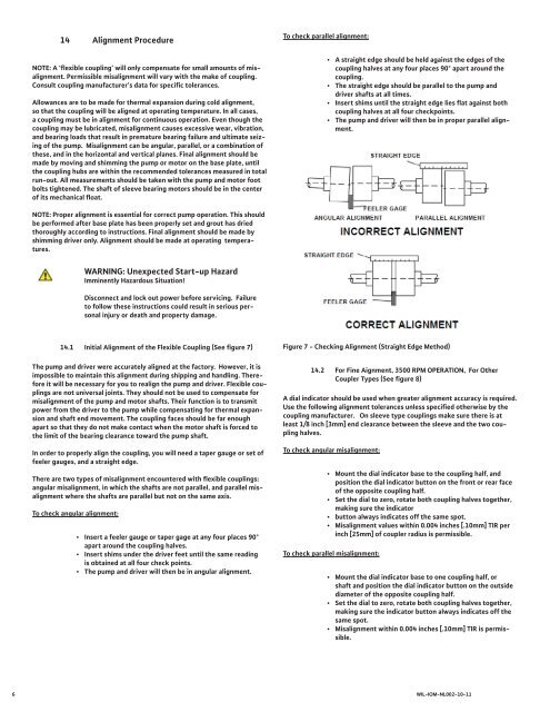
14 Alignment ProcedureNOTE: A ‘flexible coupling’ will only compensate for small amounts of misalignment.Permissible misalignment will vary with the make of coupling.Consult coupling manufacturer’s data for specific tolerances.Allowances are to be made for thermal expansion during cold alignment,so that the coupling will be aligned at operating temperature. In all cases,a coupling must be in alignment for continuous operation. Even though thecoupling may be lubricated, misalignment causes excessive wear, vibration,and bearing loads that result in premature bearing failure and ultimate seizingof the pump. Misalignment can be angular, parallel, or a combination ofthese, and in the horizontal and vertical planes. Final alignment should bemade by moving and shimming the pump or motor on the base plate, untilthe coupling hubs are within the recommended tolerances measured in totalrun-out. All measurements should be taken with the pump and motor footbolts tightened. The shaft of sleeve bearing motors should be in the centerof its mechanical float.To check parallel alignment:• A straight edge should be held against the edges of thecoupling halves at any four places 90° apart around thecoupling.• The straight edge should be parallel to the pump anddriver shafts at all times.• Insert shims until the straight edge lies flat against bothcoupling halves at all four checkpoints.• The pump and driver will then be in proper parallel alignment.NOTE: Proper alignment is essential for correct pump operation. This shouldbe performed after base plate has been properly set and grout has driedthoroughly according to instructions. Final alignment should be made byshimming driver only. Alignment should be made at operating temperatures.WARNING: Unexpected Start-up HazardImminently Hazardous Situation!Disconnect and lock out power before servicing. Failureto follow these instructions could result in serious personalinjury or death and property damage.14.1 Initial Alignment of the Flexible Coupling (See figure 7)The pump and driver were accurately aligned at the factory. However, it isimpossible to maintain this alignment during shipping and handling. Thereforeit will be necessary for you to realign the pump and driver. Flexible couplingsare not universal joints. They should not be used to compensate formisalignment of the pump and motor shafts. Their function is to transmitpower from the driver to the pump while compensating for thermal expansionand shaft end movement. The coupling faces should be far enoughapart so that they do not make contact when the motor shaft is forced tothe limit of the bearing clearance toward the pump shaft.In order to properly align the coupling, you will need a taper gauge or set offeeler gauges, and a straight edge.There are two types of misalignment encountered with flexible couplings:angular misalignment, in which the shafts are not parallel, and parallel misalignmentwhere the shafts are parallel but not on the same axis.To check angular alignment:• Insert a feeler gauge or taper gage at any four places 90°apart around the coupling halves.• Insert shims under the driver feet until the same readingis obtained at all four check points.• The pump and driver will then be in angular alignment.Figure 7 - Checking Alignment (Straight Edge Method)14.2 For Fine Aignment, 3500 RPM OPERATION, For OtherCoupler Types (See figure 8)A dial indicator should be used when greater alignment accuracy is required.Use the following alignment tolerances unless specified otherwise by thecoupling manufacturer. On sleeve type couplings make sure there is atleast 1/8 inch [3mm] end clearance between the sleeve and the two couplinghalves.To check angular misalignment:• <strong>Mount</strong> the dial indicator base to the coupling half, andposition the dial indicator button on the front or rear faceof the opposite coupling half.• Set the dial to zero, rotate both coupling halves together,making sure the indicator• button always indicates off the same spot.• Misalignment values within 0.004 inches [.10mm] TIR perinch [25mm] of coupler radius is permissible.To check parallel misalignment:• <strong>Mount</strong> the dial indicator base to one coupling half, orshaft and position the dial indicator button on the outsidediameter of the opposite coupling half.• Set the dial to zero, rotate both coupling halves together,making sure the indicator button always indicates off thesame spot.• Misalignment within 0.004 inches [.10mm] TIR is permissible.6 WIL-IOM-<strong>NL</strong>002-10-11