CNC PROGRAMMING ENHANCED LEARNING ... - Caminstructor
CNC PROGRAMMING ENHANCED LEARNING ... - Caminstructor
CNC PROGRAMMING ENHANCED LEARNING ... - Caminstructor

Create successful ePaper yourself
Turn your PDF publications into a flip-book with our unique Google optimized e-Paper software.
<strong>CNC</strong> <strong>PROGRAMMING</strong><br />
<strong>ENHANCED</strong> <strong>LEARNING</strong><br />
SYSTEM<br />
MILL<br />
By Matthew Manton and Duane Weidinger<br />
Sample<br />
not for<br />
Distribution
<strong>CNC</strong> Programming Enhanced Learning System - Mill<br />
Published by<br />
CamInstructor Incorporated<br />
330 Chandos Crt.<br />
Kitchener, Ontario<br />
N2A 3C2<br />
www.caminstructor.com<br />
Date: May 1, 2011<br />
Author: Matthew Manton and Duane Weidinger<br />
ISBN: 978-1-897466-88-9<br />
Copyright © 2011 CamInstructor Inc. - All rights reserved.<br />
This book is protected under the copyright laws of Canada and the United States. All rights are reserved. This<br />
document may not, in whole or part, be copied, photocopied, reproduced, translated or reduced to any<br />
electronic medium or machine-readable form without prior consent, in writing, from CamInstructor Inc.<br />
National Library of Canada Cataloguing in Publication<br />
To order additional copies of the book contact:<br />
CamInstructor Inc.<br />
330 Chandos Crt, Kitchener, ON, N2A 3C2<br />
Phone 1-877-873-6867<br />
Fax 1-866-741-8421<br />
email sales@caminstructor.com<br />
Limit of Liability/Disclaimer of Warranty: While the Publisher and Author have used their best efforts in<br />
preparing this book, they make no representations or warranties with respect to the accuracy or<br />
completeness of the contents of this book and specifically disclaim any implied warranties of<br />
merchantability or fitness for a particular purpose. No warranty may be created or extended by<br />
representatives. The advice and strategies contained in this book may not be suitable for the readers or<br />
users situation. Neither the publisher nor author shall be liable for any damage, loss or any other damages,<br />
including but not limited to special, incidental, consequential, or other damages including personal.<br />
Sample<br />
Notice<br />
CamInstructor Inc. reserves the right to make improvements to this book at any time and without notice.<br />
Trademarks<br />
All brands are the trademark of their respective owners.<br />
Printed in Canada<br />
not for<br />
Distribution<br />
Requirements<br />
Use of the Multi-media CD/DVD requires a computer with speakers, and CD/DVD ROM.<br />
September 1, 2011
TABLE OF CONTENTS<br />
LESSON-1 ..ABSOLUTE & INCREMENTAL POSITIONING ........................................................1<br />
EXERCISES 1 THROUGH 4 ABSOLUTE & INCREMENTAL ........................................... 5<br />
LESSON-2 .. INTRODUCTION TO <strong>CNC</strong> CODES .......................................................................9<br />
AUTOMATIC TOOL CHANGER STANDARD TOOL CAROUSEL ................................... 10<br />
COMMONLY USED PREPARATORY G-CODES ........................................................... 11<br />
COMMONLY USED MISCELLANEOUS M-CODES ...................................................... 12<br />
EXAMPLE OF PROGRAM START-UP BLOCKS ............................................................ 13<br />
EXAMPLE OF PROGRAM END BLOCKS ..................................................................... 14<br />
EXAMPLE OF PROGRAM TOOL CHANGE BLOCKS .................................................... 14<br />
RAPID (G00) AND LINEAR (G01) INTERPOLATION ................................................... 15<br />
<strong>CNC</strong> PART #1 – SPOT DRILLING SAMPLE PROGRAM ................................................ 17<br />
LESSON-3 .. CREATING <strong>CNC</strong> PRORAMS - <strong>CNC</strong> PART #1 .........................................................19<br />
<strong>CNC</strong> PART #1 – SPOT AND DRILLING SAMPLE PROGRAM1 ..................................... 20<br />
Sample<br />
LESSON-4 .. DRILLING USING CANNED CYCLES ....................................................................23<br />
DRILLING CANNED CYCLES ....................................................................................... 25<br />
<strong>CNC</strong> PART #1 – SPOT AND DRILLING PROGRAM USING G81 ................................... 26<br />
not for<br />
<strong>CNC</strong> PART #1 – WHAT COULD GO WRONG? ............................................................ 28<br />
Distribution
TABLE OF CONTENTS<br />
LESSON-5 .. DRILLING USING CANNED CYCLES ....................................................................29<br />
<strong>CNC</strong> PART #2 - SPOT AND DRILLING PROGRAM USING G81 .................................... 30<br />
<strong>CNC</strong> PART #2 - CREATE THE PROGRAM TO SPOT AND DRILL .................................. 32<br />
<strong>CNC</strong> - PART #2 - TYPING UP YOUR PROGRAM USING WINDOWS NOTEPAD........... 34<br />
<strong>CNC</strong> - PART #2 - BACKPLOTTING .............................................................................. 37<br />
<strong>CNC</strong> - PART #3 - CREATE THE PROGRAM ................................................................. 39<br />
<strong>CNC</strong> - PART #3 - BACKPLOTTING .............................................................................. 43<br />
<strong>CNC</strong> - PART #4 - CREATE THE PROGRAM ................................................................. 45<br />
LESSON-6 .. STRAIGHT LINE MILLING – LINEAR INTERPOLATION ..........................................49<br />
EXERCISE #1 - ABSOLUTE & INCREMENTAL POSITIONING ...................................... 50<br />
<strong>CNC</strong> PART #5 – STRAIGHT LINE MILLING SAMPLE PROGRAM ................................. 51<br />
<strong>CNC</strong> PART #6 – STRAIGHT LINE MILLING SAMPLE PROGRAM ................................. 54<br />
<strong>CNC</strong> PART #7 – CREATE THE PROGRAM ................................................................... 57<br />
Sample<br />
<strong>CNC</strong> PART #8 – CREATE THE PROGRAM ................................................................... 60<br />
LESSON-7 .. CIRCULAR INTERPOLATION ..............................................................................63<br />
CIRCULAR INTERPOLATION EXERCISES .................................................................... 65<br />
not for<br />
CIRCULAR INTERPOLATION SAMPLE PROGRAMS .................................................... 72<br />
LESSON-8 .. CIRCULAR INTERPOLATION ..............................................................................77<br />
Distribution<br />
<strong>CNC</strong> PART #9 – CIRCULAR INTERPOLATION CREATE THE PROGRAM ...................... 78<br />
<strong>CNC</strong> PART #10 - CIRCULAR INTERPOLATION CREATE THE PROGRAM ..................... 84<br />
Table of Contents - 2
TABLE OF CONTENTS<br />
LESSON-9 .. CIRCULAR INTERPOLATION ..............................................................................91<br />
<strong>CNC</strong> PART #11 - CIRCULAR INTERPOLATION CREATE THE PROGRAM ..................... 92<br />
<strong>CNC</strong> PART #12 - CIRCULAR INTERPOLATION CREATE THE PROGRAM ..................... 98<br />
LESSON-10 CUTTER COMPENSATION .................................................................................105<br />
INTRODUCTION TO CUTTER COMPENSATION ......................................................... 106<br />
<strong>CNC</strong> PART #13 - CUTTER COMPENSATION CREATE THE PROGRAM ........................ 108<br />
<strong>CNC</strong> PART #14 - CUTTER COMPENSATION CREATE THE PROGRAM ........................ 115<br />
APPENDIX ..........................................................................................................................123<br />
EXTRA <strong>CNC</strong> <strong>PROGRAMMING</strong> EXERCISES .................................................................. 124<br />
PREPATORY FUNCTIONS – G-CODES ........................................................................ 131<br />
MISCELLANEOUS FUNCTIONS – M-CODES .............................................................. 134<br />
STANDARD DRILL SIZES – INCHES ............................................................................ 136<br />
INCH TAP DRILL SIZES ............................................................................................... 137<br />
Sample<br />
METRIC TAP DRILL SIZES .......................................................................................... 138<br />
NCPLOT INSTALLATION GUIDE ................................................................................. 139<br />
not for<br />
Distribution<br />
Table of Contents - 3
Sample<br />
not for<br />
Distribution<br />
Table of Contents - 4
<strong>CNC</strong> <strong>PROGRAMMING</strong><br />
WORKBOOK<br />
Sample<br />
LESSON-1<br />
not for<br />
ABSOLUTE & INCREMENTAL POSITIONING<br />
Distribution<br />
Page 1
LESSON-1 – Introduction<br />
The <strong>CNC</strong> Enhanced Learning System includes the <strong>CNC</strong> Programming Student Workbook and a DVD with the<br />
following Videos and support files on it.<br />
1. Self-Learning Videos<br />
2. NCPlot Installation Software<br />
To view what’s on the DVD just follow the instructions below. We encourage you to take a few moments to<br />
watch the Getting Started video on the DVD as it provides an overview of how the system works.<br />
Just pop the DVD into your computer, the autorun feature should display the AutoPlay window. Click on the<br />
Run <strong>CNC</strong>-Mill.exe file as shown below. Note, if this window is not displayed after putting the DVD into your<br />
computer, go to the file manager feature on your computer and select the DVD drive and double click on the<br />
Run <strong>CNC</strong>-Mill.exe file.<br />
The following Menu Screen should appear;<br />
Page 2<br />
Sample<br />
not for<br />
Distribution<br />
Lesson 1 - 2
The Menu is your easy access to the Instructional Videos that will guide you through the content and<br />
provide you with all the information you need to get through this workbook. You will notice that there are<br />
10 Lessons and a Getting Started link. Each Lesson matches the corresponding lesson in this workbook. Be<br />
sure to watch the video first, it will guide you to refer to the workbook.<br />
Your first task is to watch the Getting Started Video. Don’t worry about taking notes or filling out anything in<br />
the workbook while you watch the Getting Started Video, it is just a preview of what to expect.<br />
The second item on the DVD is the NCPlot installation file. We have provided this to you free of charge so<br />
you can install NCPlot onto your computer. NCPlot Software enables you to type in the <strong>CNC</strong> Code (G Code)<br />
and watch what it will do. It is a handy tool to see if your <strong>CNC</strong> Programs are correct. To access the NCPlot<br />
installation file put the DVD into your computer and locate the NCPlot_V1-2 folder as shown below.<br />
Double click on the folder and then double click on the NCPlot_v120.exe file and follow the onscreen<br />
instructions.<br />
Sample<br />
not for<br />
Distribution<br />
Lesson 1 - 3<br />
Page 3
Okay let’s get started.<br />
LESSON-1 – Introduction<br />
Step 1 - Plug in your headphones or make sure your speakers are plugged in and turned on.<br />
Step 2 - Put the DVD into your computer and launch the menu.<br />
Step 3 - Click on Getting Started and watch the video through to the end. Feel free to pause and rewind the<br />
video if you need to watch something again.<br />
Step 4 - Click on Lesson 1 and then click on Lesson-1 – Unit-1, as indicated it is 9 minutes long.<br />
Step 5 - Proceed through the Videos in the proper order and make sure to follow along with the Workbook.<br />
Good luck and have fun.<br />
Page 4<br />
Sample<br />
not for<br />
Distribution<br />
Lesson 1 - 4
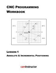
LESSON-1 – EXERCISE #1 - ABSOLUTE & INCREMENTAL POSITIONING<br />
G90 ABSOLUTE <strong>PROGRAMMING</strong><br />
All axis motions are based on a fixed zero reference point, known as ABSOLUTE ZERO (part zero).<br />
Each coordinate is in relation to this absolute zero using Cartesian Co-ordinates.<br />
G91 INCREMENTAL <strong>PROGRAMMING</strong><br />
All axis motions are based on the distance to the next location.<br />
Each coordinate is based on how far the cutter is to move from start to finish.<br />
� STARTING AT THE POINT O (ORIGIN), DESCRIBE THE PATH FROM O THROUGH ALL 9 POINTS AND<br />
BACK TO THE POINT O USING G90 & G91<br />
Sample<br />
G90 X Y G91 X Y<br />
O (Origin) 0 0 O → 1 3 3<br />
not for<br />
1 3 3 1 → 2 0 2<br />
2 3 5 2 → 3 2 2<br />
3 5 7 3 → 4 -6 0<br />
4 -1 7 4 → 5 -2 -3<br />
Distribution<br />
5 -3 4 5 → 6 -3 -6<br />
6 -6 -2 6 → 7 4 -3<br />
7 -2 -5 7 → 8 6 -1<br />
8 4 -6 8 → 9 3 3<br />
9 7 -3 9 → O -7 3<br />
Lesson 1 - 5<br />
Page 5
Page 6<br />
LESSON-1 – EXERCISE #2 - ABSOLUTE & INCREMENTAL POSITIONING<br />
G90 ABSOLUTE <strong>PROGRAMMING</strong><br />
All axis motions are based on a fixed zero reference point, known as ABSOLUTE ZERO (part zero).<br />
Each coordinate is in relation to this absolute zero using Cartesian Co-ordinates.<br />
G91 INCREMENTAL <strong>PROGRAMMING</strong><br />
All axis motions are based on the distance to the next location.<br />
Each coordinate is based on how far the cutter is to move from start to finish.<br />
� STARTING AT THE POINT O (ORIGIN), DESCRIBE THE PATH FROM O THROUGH ALL 9 POINTS AND<br />
BACK TO THE POINT O USING G90 & G91<br />
Sample<br />
G90 X Y G91 X Y<br />
O (Origin) O → 1<br />
not for<br />
1 1 → 2<br />
2 2 → 3<br />
3 3 → 4<br />
4 4 → 5<br />
5 5 → 6<br />
6 6 → 7<br />
7 7 → 8<br />
8 8 → 9<br />
9 9 → O<br />
Distribution<br />
Lesson 1 - 6
LESSON-1 – EXERCISE #3 - ABSOLUTE & INCREMENTAL POSITIONING<br />
G90 ABSOLUTE <strong>PROGRAMMING</strong><br />
All axis motions are based on a fixed zero reference point, known as ABSOLUTE ZERO (part zero).<br />
Each coordinate is in relation to this absolute zero using Cartesian Co-ordinates.<br />
G91 INCREMENTAL <strong>PROGRAMMING</strong><br />
All axis motions are based on the distance to the next location.<br />
Each coordinate is based on how far the cutter is to move from start to finish.<br />
� STARTING AT THE POINT O (ORIGIN), DESCRIBE THE PATH FROM O THROUGH ALL 9 POINTS AND<br />
BACK TO THE POINT O USING G90 & G91<br />
Sample<br />
G90 X Y G91 X Y<br />
O (Origin) O → 1<br />
1 1 → 2<br />
not for<br />
2 2 → 3<br />
3 3 → 4<br />
4 4 → 5<br />
5 5 → 6<br />
Distribution<br />
6 6 → 7<br />
7 7 → 8<br />
8 8 → 9<br />
9 9 → O<br />
Lesson 1 - 7<br />
Page 7
Page 8<br />
LESSON-1 – EXERCISE #4 - ABSOLUTE & INCREMENTAL POSITIONING<br />
� STARTING AT THE POINT O (ORIGIN), DESCRIBE THE PATH FROM O THROUGH ALL 9 POINTS AND<br />
BACK TO THE POINT O USING G90 & G91<br />
G90 X Y G91 X Y<br />
Sample<br />
O (Origin) 0 0 O → 1 0.750 0.500<br />
1 0.750 0.500 1 → 2 -0.200 1.875<br />
2 0.550 2.375 2 → 3 0.400 -1.000<br />
3 0.950 1.375 3 → 4<br />
not for<br />
4 4 → 5<br />
5 5 → 6<br />
6 6 → 7<br />
7 7 → 8<br />
8 8 → 9<br />
9 9 → O<br />
Distribution<br />
Lesson 1 - 8
<strong>CNC</strong> <strong>PROGRAMMING</strong><br />
WORKBOOK<br />
CODE FUNCTION<br />
G00<br />
G01<br />
Rapid traverse motion; This is used for non-cutting rapid moves of the machine axis, or<br />
rapid retract moves after cuts have been completed.<br />
Maximum rapid motion (I.P.M.) of a <strong>CNC</strong> Machine will vary dependent on machine<br />
model.<br />
Linear interpolation motion; Used for cutting in a straight line under a controlled<br />
feedrate. Maximum feed rate (I.P.M.) of a <strong>CNC</strong> Machine will vary depending on the<br />
model of the machine.<br />
G02 Circular Interpolation, Clockwise<br />
G03 Circular Interpolation, Counterclockwise<br />
G04 Dwell<br />
G17 Circular Motion XY Plane Selection<br />
G20 Verify Inch Coordinate Positions<br />
G21 Verify Metric Coordinate Positions<br />
G28<br />
Machine Home (Rapid traverse) G91 is required for rapid move to the G28 reference<br />
point.<br />
Sample<br />
G40 Cutter Compensation CANCEL<br />
LESSON-2<br />
not for<br />
INTRODUCTION TO <strong>CNC</strong> CODES<br />
Distribution<br />
Page 9
LESSON-2 - INTRODUCTION TO <strong>CNC</strong> CODES<br />
AUTOMATIC TOOL CHANGER<br />
STANDARD TOOL CAROUSEL<br />
The <strong>CNC</strong> Machining Center used in this text is set-up with following tools.<br />
All program examples and exercises in this workbook are using the tools and tool<br />
numbers listed below.<br />
Page 10<br />
Carousel # Tool Description<br />
1 0.125” Diameter Flat End Mill<br />
2 0.250” Diameter Flat End Mill<br />
3 0.375” Diameter Flat End Mill<br />
4 0.500” Diameter Flat End Mill<br />
5 0.750” Diameter Flat End Mill<br />
Sample<br />
6 0.375” Diameter Spot Drill<br />
7 0.250” Diameter Drill<br />
not for<br />
8 0.201” Diameter Drill – Number 7 drill<br />
9 0.25”-20 UNC Tap<br />
10 #4 Center Drill<br />
Distribution<br />
Lesson 2 - 2
COMMONLY USED PREPARATORY G CODES<br />
CODE FUNCTION<br />
G00<br />
G01<br />
Rapid traverse motion; This is used for non-cutting rapid moves of the machine axis, or<br />
rapid retract moves after cuts have been completed.<br />
Maximum rapid motion (I.P.M.) of a <strong>CNC</strong> Machine will vary dependent on machine<br />
model.<br />
Linear interpolation motion; Used for cutting in a straight line under a controlled<br />
feedrate. Maximum feed rate (I.P.M.) of a <strong>CNC</strong> Machine will vary depending on the<br />
model of the machine.<br />
G02 Circular Interpolation, Clockwise<br />
G03 Circular Interpolation, Counterclockwise<br />
G04 Dwell<br />
G17 Circular Motion XY Plane Selection<br />
G20 Verify Inch Coordinate Positions<br />
G21 Verify Metric Coordinate Positions<br />
G28<br />
Machine Home (Rapid traverse) G91 is required for rapid move to the G28 reference<br />
point.<br />
G40 Cutter Compensation CANCEL<br />
G41 Cutter Compensation LEFT of the programmed path<br />
G42 Cutter Compensation RIGHT of the programmed path<br />
G43 Tool Length Compensation<br />
G49 Tool Length Compensation CANCEL<br />
Sample<br />
G53 Positions the machine axis relative to Machine Home. It is non modal.<br />
G54 Work Coordinate #1 (Part zero offset location)<br />
G80 Canned Cycle CANCEL<br />
G81 Drill Canned Cycle<br />
not for<br />
G82 Spot Drill Canned Cycle<br />
G83 Peck Drill Canned Cycle<br />
G84 Tapping Canned Cycle<br />
G90 Absolute Programming Positioning<br />
G91 Incremental Programming Positioning<br />
G98 Canned Cycle Initial Point Return<br />
G99 Canned Cycle Rapid (R) Plane Return<br />
Distribution<br />
Lesson 2 - 3<br />
Page 11
COMMONLY USED MISCELLANEOUS M CODES<br />
CODE FUNCTION<br />
M00<br />
M01<br />
M03<br />
The M00 code is used for a Program Stop. The spindle stops and the coolant is turned<br />
off.<br />
Pressing CYCLE START again will continue the program.<br />
The M01 code is used for an Optional Program Stop command.<br />
Pressing the OPT STOP key on the control panel signals the machine to perform a stop<br />
command when the control reads an M01 command. It will then perform like an M00.<br />
Optional stops are useful when machining the first part to allow for inspection of the<br />
part as it is machined.<br />
Starts the spindle CLOCKWISE used for most machining. Must have a spindle speed<br />
defined.<br />
The M03 is used to turn the spindle on at the beginning of program or after a tool<br />
change.<br />
M04 Starts the spindle COUNTERCLOCKWISE. Must have a spindle speed defined.<br />
M05<br />
M06<br />
STOPS the spindle.<br />
The M05 is used to turn the spindle off at the end of program or before a tool change.<br />
If the coolant is on, the M05 will turn it off.<br />
The tool change command along with a tool number will action a tool change. This<br />
command will automatically stop the spindle, Z-axis will move up to the machine zero<br />
position and the selected tool will be put in the spindle. The coolant pump will turn off<br />
right before executing the tool change.<br />
M08 Coolant ON command.<br />
M09 Coolant OFF command.<br />
M30 Program End and Reset to the beginning of program.<br />
Note: Only one “M” code can be used per line. And the M-codes will be the last command to be executed in<br />
a line, regardless of where it is located in that line.<br />
Page 12<br />
Sample<br />
not for<br />
Distribution<br />
Lesson 2 - 4
%<br />
O00023<br />
N10 G20<br />
EXAMPLE OF PROGRAM START-UP BLOCKS<br />
N20 G00 G17 G40 G49 G80 G90<br />
N30 T8 M06<br />
Sample<br />
N40 G00 G90 G54 X1.0 Y1.0 S4000 M03<br />
N50 G43 H8 Z2. 0<br />
Programs must begin and end with “%” depending<br />
on the type of control.<br />
Letter “O” and up to a five digit program number.<br />
Blocks are always terminated by the “;” symbol:<br />
End of Block (EOB)<br />
Nnn - Sequence Number<br />
G20 - Verify Inch<br />
not for<br />
G00 - Rapid Traverse<br />
G17 - X, Y Circular Plane Selection<br />
G40 - Cutter Compensation Cancel<br />
G49 - Tool Length Compensation Cancel<br />
G80 - Canned Cycle Cancel<br />
G90 - Absolute Programming<br />
Lesson 2 - 5<br />
Startup<br />
Block<br />
(Machine<br />
Default<br />
Setting)<br />
T8 - Tool number #8 to be loaded into the spindle.<br />
M06 - Tool Change<br />
G00 - Rapid Traverse<br />
G90 - Activates control to be in ABSOLUTE.<br />
G54 - Selects work coordinate offset system No. 1<br />
X__ - Axis move to initial X position.<br />
Y__ - Axis move to initial Y position.<br />
S4000 - Spindle speed 4000 RPM for this tool.<br />
M03 - Turns the spindle on in a clockwise direction<br />
G43 - Tool Length Compensation: Recognizes the<br />
tool length offset value stored in the Hnn code offset<br />
display register in the offset length display.<br />
H8 - Defines to the control the offset register the<br />
tool offset value is stored in.<br />
* Tool Length offset # = Tool #<br />
Z2.0 - Informs the control to move from full spindle<br />
retract to this Z value and apply the tool length<br />
offset.<br />
Distribution<br />
Page 13
N200 G00 Z2.0<br />
EXAMPLE OF PROGRAM END BLOCKS<br />
G00 - Rapid Traverse<br />
Z2.0 – Retracts tool to 2.0 above part zero<br />
N210 M05 M05 – Turn off spindle<br />
N220 G28 G91 Z0<br />
* N220 G53 Z0<br />
N230 G28 X0 Y0<br />
* N230 G53 X0 Y0<br />
G91 - Incremental Programming<br />
G28 - Machine Zero Return<br />
Z0 - Z axis in the up direction to<br />
machine zero<br />
G28 - Machine Zero Return<br />
X0 - X axis to machine zero<br />
Y0 - Y axis to machine zero<br />
N240 M30 M30 – End of Program and Reset<br />
N100 G00 Z2.0<br />
EXAMPLE OF PROGRAM TOOL CHANGE LINES<br />
N110 M05 M05 – Turn off spindle<br />
Lesson 2 - 6<br />
Send to machine<br />
zero Z-axis first to<br />
avoid any crash.<br />
*G53 is another way<br />
to return to machine<br />
zero<br />
Rapid Traverse and Retracts tool to 2.0 above part<br />
zero<br />
N120 G28 G91 Z0 ; / *N120 G53 Z0 Machine Zero Return - Z axis Send to machine<br />
zero Z-axis first to<br />
N130 G28 X0 Y0 / *N130 G53 X0 Y0 Machine Zero Return - X, Y axis avoid any crash.<br />
N140 M01 Optional Program Stop<br />
N150 T9 M06 Tool Change - Tool # 9<br />
N160 G00 G90 G54 X1.0 Y1.0 S4000 M03 Turn on the spindle and Rapid traverse to X1. Y1.<br />
N170 G43 H9 Z2.0 Tool Length compensation for Tool #9 (H9)<br />
*G53 - Positions the machine axis relative to Machine Home. It is non modal.<br />
Page 14<br />
Sample<br />
not for<br />
Distribution
RAPID G00 AND LINEAR G01 INTERPOLATION<br />
G00 RAPID TRAVERSE<br />
This code is used for rapid motion of the cutter in air to traverse from one position to another as<br />
fast as possible. This code will work for all axis motion up to three axes at once.<br />
This G00 code is modal and causes all the following blocks to be in rapid motion until another<br />
Group 01 code is specified. The actual rapid federate is dependent on the machine.<br />
Generally, rapid motions "will not" be in a straight line. All the axes specified are moved at the<br />
maximum speed and will not necessarily complete each axis move at the same time. It activates<br />
each axis drive motor independently of each other and, as a result, the axis with the shortest move<br />
will reach its destination first. So you need to be careful of any obstructions to avoid with this type<br />
of rapid move.<br />
� G00 is used when you are positioning the cutter in ‘fresh air’.<br />
� Retracting from a hole you have drilled.<br />
� Rapid traverse is not used when cutting the part.<br />
� Used incorrectly, rapid traverse will break a cutter very easily.<br />
G01 LINEAR INTERPOLATION<br />
This G code provides for straight line (linear) motion with programmed feedrate for all axis motions<br />
Sample<br />
from point to point. Motion can occur up to three axes at once.<br />
All axes specified will start at the same time and proceed to their destination and arrive<br />
simultaneously at the specified feedrate.<br />
To program a feedrate, the F command is used. The F command is modal and may be specified in a<br />
previous block.<br />
G01 is used for<br />
� Drilling a hole<br />
� Machining a slot<br />
� Machining a profile<br />
not for<br />
Distribution<br />
Lesson 2 - 7<br />
Page 15
Page 16<br />
Sample<br />
LESSON-2 - <strong>CNC</strong> - PART #1<br />
not for<br />
Distribution<br />
Lesson 2 - 8
LESSON-2 - <strong>CNC</strong> - PART #1<br />
� WORK OUT THE X AND Y COORDIANTES FOR HOLES 1,2 AND 3<br />
� X0Y0 is at the centre of the part<br />
Sample<br />
not for<br />
G90 X Y<br />
1<br />
2<br />
3<br />
Distribution<br />
Lesson 2 - 9<br />
Page 17
LESSON-2 - <strong>CNC</strong> - PART #1<br />
� PROGRAM TO SPOT DRILL THE THREE HOLES ONLY USING A COMBINATION OF<br />
G00 AND G01 (CANNED CYCLE DRILL WILL BE USED LATER)<br />
� Below is the program to spot drill the three holes with an explanation of each block<br />
� Use a 0.375” diameter Spot Drill Tool # 6<br />
� Spindle Speed = 2750 Feed rate = 11 IPM<br />
� Spot Drill Depth = Z-0.150”<br />
� X0Y0 is at the centre of the part<br />
� Z=0 is the top of the part.<br />
� Information inside the parenthesis ( ) is a comment.<br />
� The <strong>CNC</strong> control will ignore all text between the parenthesis<br />
% (Program must begin and end with a %)<br />
O1 ( Program #1 - <strong>CNC</strong>-PART-1-SPOT DRILLING ONLY )<br />
N10 G20 (Inch programming)<br />
N20 G00 G17 G40 G49 G80 G90 (MACHINE DEFAULT SETTING)<br />
N30 T06 M06 (T6-Select tool number 6 to be loaded M06-Activates the tool changer)<br />
N40 G00 G90 G54 X-1.0 Y-0.875 S2750 M03 – (Rapid to the X and Y position and turn on the spindle at<br />
2750 RPM)<br />
N50 G43 H06 Z0.1 (G43 - Activate the tool offset value stored in H06 and rapid to Z0.1)<br />
N60 G01 Z-0.15 F11.0 (Hole #1 - Feed down to Z depth at 11 inches per minute)<br />
N70 G00 Z0.1 (G00- Retract out of hole #1 at rapid to 0.1 above the top of the work piece)<br />
N80 X0 Y0 (G00 is modal - Move at rapid in the X and Y axis to hole #2)<br />
N90 G01 Z-0.15 (Hole #2 - Feed down to Z depth at 11 inches per minute, Feed rate is modal)<br />
N100 G00 Z0.1 (G00- Retract out of hole #2 at rapid to 0.1 above the top of the work piece)<br />
N110 X1.0 Y0.875 (G00 is modal - Move at rapid in the X and Y axis to hole #3)<br />
N120 G01 Z-0.15 (Hole #3 - Feed down to Z depth at 11 inches per minute, Feed rate is modal)<br />
N130 G53 G00 Z0 M05 (G53 – Machine Zero positioning, non modal. Rapid to machine zero in Z, switch<br />
spindle off)<br />
N140 G53 X-15.0 Y0 (G53 – Rapid in relation to machine zero X-15.0 and Y0)<br />
N150 M30 (Program end rewind program to the beginning)<br />
% (Program must begin and end with a %)<br />
Page 18<br />
Sample<br />
not for<br />
Distribution<br />
Lesson 2 - 10
<strong>CNC</strong> <strong>PROGRAMMING</strong><br />
WORKBOOK<br />
Sample<br />
LESSON-3<br />
not for<br />
Distribution<br />
CREATING <strong>CNC</strong> PROGRAMS - <strong>CNC</strong> PART #1<br />
Page 19
LESSON-3 - <strong>CNC</strong> - PART #1<br />
� PROGRAM TO SPOT AND DRILL THE THREE HOLES USING A COMBINATION OF<br />
G00 AND G01 (CANNED CYCLE WILL BE USED LATER)<br />
� Below is the program to spot and drill the three holes with an explanation of each block<br />
� Use a 0.375” diameter Spot Drill Tool # 6<br />
� Spot Drill Spindle Speed = 2750 Feed rate = 11 IPM<br />
� Use a 0.250” diameter Drill Tool # 7<br />
� 0.250” diameter Drill Spindle Speed = 4500 Feed rate = 15 IPM<br />
� Spot Drill Depth = Z-0.150”<br />
� Drill Depth = Z-0.350”<br />
� X0Y0 is at the centre of the part<br />
� Z=0 is the top of the part.<br />
% (Program must begin and end with a %)<br />
O2 ( Program #2 - <strong>CNC</strong>-PART-1-SPOT AND DRILLING )<br />
N10 G20 (Inch programming)<br />
N20 G00 G17 G40 G49 G80 G90 (MACHINE DEFAULT SETTING)<br />
(SPOT DRILL 0.25” HOLES)<br />
N30 T06 M06 (T6-Select tool number 6 to be loaded M06-Activates the tool changer)<br />
N40 G00 G90 G54 X-1.0 Y-0.875 S2750 M03 (Rapid to the X and Y position of Hole #1 and turn on the<br />
spindle at 2750 RPM)<br />
N50 G43 H06 Z0.1 (G43 - Activate the tool offset value stored in H06 and rapid to Z0.1)<br />
N60 G01 Z-0.15 F11.0 (Hole #1 - Feed down to Z depth at 11 inches per minute)<br />
N70 G00 Z0.1 (G00- Retract out of hole #1 at rapid to 0.1 above the top of the work piece)<br />
N80 X0 Y0 (G00 is modal - Move at rapid in the X and Y axis to Hole #2)<br />
N90 G01 Z-0.15 (Hole #2 - Feed down to Z depth at 11 inches per minute, Feed rate is modal)<br />
N100 G00 Z0.1 (G00- Retract out of hole #2 at rapid to 0.1 above the top of the work piece)<br />
N110 X1.0 Y0.875 (G00 is modal - Move at rapid in the X and Y axis to hole #3)<br />
N120 G01 Z-0.15 (Hole #3 - Feed down to Z depth at 11 inches per minute, Feed rate is modal)<br />
N130 G53 G00 Z0 M05 (G53 – Machine Zero positioning, non modal. Rapid to machine zero in Z, switch<br />
spindle off)<br />
N140 G53 X-15.0 Y0 (G53 – Rapid in relation to machine zero X-15.0 and Y0)<br />
(DRILL 0.25” HOLES)<br />
N160 T07 M06 (T7-Select tool number 7 to be loaded M06-Activates the tool changer)<br />
N170 G00 G90 G54 X-1.0 Y-0.875 S4500 M03 (Rapid to the X and Y position of Hole #1 and turn on the<br />
spindle at 4500 RPM)<br />
N180 G43 H07 Z0.1 (G43 - Activate the tool offset value stored in H07 and rapid to Z0.1)<br />
N190 G01 Z-0.35 F15.0 (Hole #1 - Feed down to Z depth at 15 inches per minute through part)<br />
N200 G00 Z0.1 (G00- Retract out of hole #1 at rapid to 0.1 above the top of the work piece)<br />
Page 20<br />
Sample<br />
not for<br />
Distribution<br />
Lesson 3 - 2
LESSON-3 - <strong>CNC</strong> - PART #1 - Continued<br />
N210 X0 Y0 (G00 is modal - Move at rapid in the X and Y axis to hole #2)<br />
N220 G01 Z-0.35 (Hole #2 - Feed down to Z depth, at 15 inches per minute, Feed rate is modal)<br />
N230 G00 Z0.1 (G00- Retract out of hole #2 at rapid to 0.1 above the top of the work piece)<br />
N240 X1.0 Y0.875 (G00 is modal - Move at rapid in the X and Y axis to hole #3)<br />
N250 G01 Z-0.35 (Hole #3 - Feed down to Z depth at 15 inches per minute, Feed rate is modal)<br />
N260 G53 G00 Z0 M05 (G53 – Machine Zero positioning, non modal. Rapid to machine zero in Z, switch<br />
spindle off)<br />
N270 G53 X-15.0 Y0 (G53 – Rapid in relation to machine zero X-15.0 and Y0)<br />
N270 M30 (Program end rewind program to the beginning)<br />
% (Program must begin and end with a %)<br />
Sample<br />
not for<br />
Distribution<br />
Lesson 3 - 3<br />
Page 21
Page 22<br />
Sample<br />
not for<br />
Distribution<br />
Lesson 3 - 4
<strong>CNC</strong> <strong>PROGRAMMING</strong><br />
WORKBOOK<br />
Sample<br />
LESSON-4<br />
not for<br />
DRILLING USING CANNED CYCLES<br />
Distribution<br />
Page 23
LESSON-4 DRILL CANNED CYCLE G81<br />
G80 CANCEL CANNED CYCLE<br />
A canned cycle permits multiple function programming on one block.<br />
A canned cycle is canceled with G80.<br />
G81 CANNED CYCLE DRILL<br />
Format: G99 G81 Z-0.625 R0.1 F10.<br />
X Rapid X location (Optional)<br />
Y Rapid Y location (Optional)<br />
Z Z-depth (Feed to Z-depth starting from R Plane)<br />
R R-Plane (Rapid point to start feeding)<br />
F Feed rate in inches/min<br />
This G code permits the inclusion of multiple axis motions on one block of program. It is used to<br />
reduce the length of program. The figure below shows the axis motions that are included with a<br />
Canned Cycle Drill.<br />
All Z axis motions are in ABSOLUTE with any other axis motions unaffected.<br />
In a canned cycle drill, the cutter moves at rapid to the X and Y, then to a height above the part at<br />
rapid rate to the R Plane, which is a point above the work surface. From the R Plane the cutter feeds<br />
to the Z-depth at the specified feedrate. When the cutter reaches the Z depth, it retracts at rapid<br />
rate to the R Plane. G99 returns the tool to the R Plane after each hole, G98 returns the tool to the initial<br />
starting plane.<br />
Page 24<br />
Sample<br />
not for<br />
Distribution<br />
Lesson 4 - 2
DEEP HOLE PECK DRILL CANNED CYCLE G83<br />
G83 DEEP HOLE PECK DRILL CANNED CYCLE<br />
Format : G99 G83 Z-2.5 Q0.5 R0.1 F10. / G99 G83 Z-2.18 I0.5 J0.1 K0.2 R0.1 F9.<br />
X* Rapid X-axis location<br />
Y* Rapid Y-axis location<br />
Z Z-depth (feed to Z-depth starting from R plane)<br />
Q* Pecking equal incremental depth amount (if I, J and K are not used)<br />
I* Size of first peck depth (if Q is not used)<br />
J* Amount reducing each peck after first peck depth (if Q is not used)<br />
K* Minimum peck depth (if Q is not used)<br />
P Dwell time at Z-depth<br />
R R-plane (rapid point to start feeding)<br />
F Feed rate in inches (mm) per minute<br />
* Indicates optional<br />
This G code is similar to G81 but is used for drilling when the tool must be withdrawn periodically<br />
to allow chips to be removed from the hole.<br />
This cycle allows the tool to rapid to the R Plane, feeds towards the Z depth in increments<br />
(traversing to the R Plane and back to the point where drilling was interrupted after each<br />
increment) until the tool reaches the final Z depth.<br />
Sample<br />
not for<br />
Distribution<br />
Lesson 4 - 3<br />
Page 25
LESSON-4 - <strong>CNC</strong> - PART #1<br />
� CREATE THE PROGRAM TO SPOT AND DRILL THE THREE HOLES USING CANNED<br />
CYCLE G81<br />
� Use a 0.375” diameter Spot Drill Tool # 6<br />
� Spot Drill Spindle Speed = 2750 Feed rate = 11 IPM<br />
� Use a 0.250” diameter Drill Tool # 7<br />
� 0.250” diameter Drill Spindle Speed = 4500 Feed rate = 15 IPM<br />
� Spot Drill Depth = Z-0.150”<br />
� Drill Depth = Z-0.350”<br />
� X0Y0 is at the centre of the part<br />
� Z=0 is the top of the part.<br />
% (Program must begin and end with a %)<br />
O3 ( Program #3 - <strong>CNC</strong>-PART-1-SPOT AND DRILLING USING CANNED CYCLE DRILL G81 )<br />
N10 G20 (Inch programming)<br />
N20 G00 G17 G40 G49 G80 G90 (MACHINE DEFAULT SETTING)<br />
N30 T06 M06 (T6-Select tool number 6 to be loaded M06-Activates the tool changer)<br />
N40 G00 G90 G54 X-1.0 Y-0.875 S2750 M03 (Rapid to the X and Y position of Hole #1 and turn on the<br />
spindle at 2750 RPM)<br />
N50 G43 H06 Z0.1 (G43 - Activate the tool offset value stored in H06 and rapid to Z0.1)<br />
N60 G99 G81 Z-0.15 R0.1 F11.0 (Hole #1 – G81 - Feed down to Z depth at 11 inches per minute,<br />
and then retract at rapid to Z0.1, this is the R0.1 value.<br />
G99 returns the drill tip to the R value after drilling each hole)<br />
N70 X0. Y0. (Hole #2 - Move at rapid in the X and Y axis to Hole #2. Feed down to Z depth at 11<br />
inches per minute and then retract at rapid to Z0.1)<br />
N80 X1.0 Y.875 (Hole #3 - Move at rapid in the X and Y axis to Hole #3. Feed down to Z depth at 11<br />
inches per minute and then retract at rapid to Z0.1)<br />
N90 G80 (Cancel Canned Cycle Drill)<br />
N100 G53 G00 Z0 M05 (G53 – Rapid to machine zero in Z, switch spindle off)<br />
N110 G53 X-15.0 Y0 (G53 – Rapid in relation to machine zero X-15.0 and Y0)<br />
(DRILL 0.25” HOLES)<br />
N120 T07 M06 (T7-Select tool number 7 to be loaded M06-Activates the tool changer)<br />
N130 G00 G90 G54 X-1.0 Y-0.875 S4500 M03 (Rapid to the X and Y position of Hole #1 and turn on the<br />
spindle at 4500 RPM)<br />
N140 G43 H07 Z0.1 (G43 - Activate the tool offset value stored in H07 and rapid to Z0.1)<br />
Page 26<br />
Sample<br />
not for<br />
Distribution<br />
Lesson 4 - 4
LESSON-4 - <strong>CNC</strong> - PART #1 - Continued<br />
N150 G99 G81 Z-0.35 R0.1 F15.0 (Hole #1 – G81 - Feed down to Z depth at 15 inches per minute,<br />
and then retract at rapid to Z0.1, this is the R0.1 value.<br />
G99 returns the drill tip to the R value after drilling each hole)<br />
N160 X0. Y0. (Hole #2 - Move at rapid in the X and Y axis to Hole #2. Feed down to Z depth at 15<br />
inches per minute and then retract at rapid to Z0.1)<br />
N170 X1.0 Y.875 (Hole #3 - Move at rapid in the X and Y axis to Hole #3. Feed down to Z depth at 15<br />
inches per minute and then retract at rapid to Z0.1)<br />
N180 G80 (Cancel Canned Cycle Drill)<br />
N190 G53 G00 Z0 M05 (G53 – Rapid to machine zero in Z, switch spindle off)<br />
N200 G53 X-15.0 Y0 (G53 – Rapid in relation to machine zero X-15.0 and Y0)<br />
N210 M30 (Program end rewind program to the beginning)<br />
% (Program must begin and end with a %)<br />
Sample<br />
not for<br />
Distribution<br />
Lesson 4 - 5<br />
Page 27
Page 28<br />
LESSON-4 – WHAT COULD GO WRONG?<br />
� IDENTIFY SOME OF THE COMMON PROBLEMS THAT COULD RESULT IN A<br />
SCRAPPED PART<br />
� Do you have X0 Y0 Z0 in the correct position?<br />
� Is the spindle switched on and off at the appropriate time<br />
� Did you use the correct X and Y coordinates for the holes?<br />
� Did you use the correct tool numbers?<br />
� Did you use the correct tool length offset number (H??) for the tool?<br />
� Did you cancel any canned cycles with G80?<br />
� Are the feed-rates correct?<br />
� Is the Z depth in the canned cycle block set to a negative value?<br />
� Is the R value in the canned cycle block set to a positive value?<br />
� What is the difference between Z2 and Z2.0? No decimal point???<br />
� What is the difference between F10 and F10.0? No decimal point???<br />
� What else?<br />
Sample<br />
not for<br />
Distribution<br />
Lesson 4 - 6
<strong>CNC</strong> <strong>PROGRAMMING</strong><br />
WORKBOOK<br />
Sample<br />
LESSON-5<br />
not for<br />
DRILLING USING CANNED CYCLES - CONTINUED<br />
Distribution<br />
Page 29
Page 30<br />
LESSON-5 - <strong>CNC</strong> - PART #2<br />
Sample<br />
not for<br />
Distribution<br />
Lesson 5 - 2
LESSON-5 - <strong>CNC</strong> - PART #2<br />
� WORK OUT THE ABSOLUTE COORDINATES FOR THE NINE HOLES<br />
� X0Y0 is at the centre of the part<br />
Sample<br />
G90 X Y<br />
1<br />
not for<br />
2<br />
3<br />
4<br />
5<br />
6<br />
7<br />
8<br />
9<br />
Distribution<br />
Lesson 5 - 3<br />
Page 31
LESSON-5 - <strong>CNC</strong> - PART #2<br />
� CREATE THE PROGRAM TO SPOT AND DRILL THE NINE HOLES USING CANNED<br />
CYCLE G81<br />
� Use a 0.375” diameter Spot Drill Tool # 6<br />
� Spot Drill Spindle Speed = 2750 Feed rate = 11 IPM<br />
� Use a 0.250” diameter Drill Tool # 7<br />
� 0.250” diameter Drill Spindle Speed = 4500 Feed rate = 15 IPM<br />
� Spot Drill Depth = Z-0.150”<br />
� Drill Depth = Z-0.350”<br />
� X0Y0 is at the centre of the part<br />
� Z=0 is the top of the part.<br />
� Type up your program and check it for correctness using NCPlot<br />
%<br />
O4 ( Program #4 - <strong>CNC</strong>-PART-2-SPOT AND DRILLING USING CANNED CYCLE DRILL G81)<br />
N10 G20<br />
N20 G00 G17 G40 G49 G80 G90 (MACHINE DEFAULT SETTING)<br />
N30<br />
Page 32<br />
Sample<br />
not for<br />
Distribution<br />
Lesson 5 - 4
LESSON-5 - <strong>CNC</strong> - PART #2 - Continued<br />
Sample<br />
not for<br />
Distribution<br />
Lesson 5 - 5<br />
Page 33
LESSON-5 - <strong>CNC</strong> - PART #2 – TYPING UP YOUR PROGRAM<br />
USING WINDOWS NOTEPAD<br />
� Use Windows Notepad to type up your <strong>CNC</strong> program<br />
1. Launch Windows Notepad Start>All Programs>Accessories>Notepad.<br />
Page 34<br />
2. Select File Save As…<br />
3. Browse to where you would like to save this file.<br />
4. Open up the Save as type drop down and change to All files.<br />
5. Encoding should be set to ANSI.<br />
6. In the File name section enter <strong>CNC</strong>-PART-2.NC This will give this file an extension of .NC<br />
7. Click on the Save button<br />
Sample<br />
not for<br />
8. Start typing your program, ALL CAPITALS for the <strong>CNC</strong> program codes. Please note on the second line<br />
of this program O4 this is a letter O.<br />
Distribution<br />
Lesson 5 - 6
LESSON-5 - <strong>CNC</strong> - PART #2 – TYPING UP YOUR PROGRAM<br />
USING WINDOWS NOTEPAD<br />
9. When you have completed typing your program Save your file, File>Save or the shortcut Ctrl+S.<br />
� Now you can check for any Letter O’s in your <strong>CNC</strong> program. Please Note there should not be any<br />
letter O’s in your <strong>CNC</strong> program, G00 is “G Zero Zero” not G Letter O!<br />
10. Select Edit>Find.<br />
Sample<br />
11. Type in the Letter O in the Find what: space. Now hit the Find Next button. There will be some<br />
letter O’s in your program, for example the Letter O in the program number at the start of the<br />
program and any notes you have in your program enclosed by parenthesis ( ). But for the coding no<br />
letter O’s.<br />
not for<br />
12. I f you do find any letter O’s change them to a Zero.<br />
Distribution<br />
Lesson 5 - 7<br />
Page 35
Page 36<br />
LESSON-5 - <strong>CNC</strong> - PART #2 – TYPING UP YOUR PROGRAM<br />
USING WINDOWS NOTEPAD<br />
13. When you have checked your program select File>Save your file or the shortcut Ctrl+S.<br />
14. You may require a print of your <strong>CNC</strong> program to do this select File>Print or the shortcut Ctrl+P.<br />
15. Select which printer you wish to send the file to and then hit the Print button<br />
Sample<br />
16. To open your <strong>CNC</strong> program at a later date launch Windows Notepad.<br />
Start>All Programs>Accessories>Notepad.<br />
17. Select File>Open.<br />
not for<br />
Distribution<br />
18. Change the Files of type: to All Files and browse for your <strong>CNC</strong> program.<br />
Lesson 5 - 8
LESSON-5 - <strong>CNC</strong> - PART #2 - BACKPLOTTING<br />
� Use NCPlot to check for correctness<br />
Note: If you do not have NCPlot installed on your computer please go to the last page of the appendix for<br />
installation instructions.<br />
1. After typing up your program in Notepad launch the NCPlot application by clicking on the icon on<br />
your desktop or Start>All Programs>NCPlot v1.3> NCPlot v1.3<br />
2. Click on the open file icon and browse to your file location and select the <strong>CNC</strong> file to plot.<br />
3. On the toolbar select XY View and Zoom Extents.<br />
4. You plot should appear as below. The point on the left of the screen shot below is the G53 X-15.0 Y0<br />
movement in the program.<br />
Sample<br />
5. On the toolbar select ZX View and Zoom Extents.<br />
not for<br />
6. On the toolbar select XY View .<br />
Distribution<br />
Lesson 5 - 9<br />
Page 37
Page 38<br />
LESSON-5 - <strong>CNC</strong> - PART #2 - BACKPLOTTING<br />
7. Review and experiment with the various pull down menu options:<br />
8. Press the function F6 on your keyboard to action a Zoom Window. Zoom in on part of your plot.<br />
9. Select Ctrl+F on your keyboard to open the Find dialog box. In the Find What section type in the<br />
letter O and then hit the Find Next button to see if there are any letter O’s in the G and M codes.<br />
Sample<br />
10. You can use NCPlot instead of Windows Notepad to type up your <strong>CNC</strong> program.<br />
not for<br />
Distribution<br />
Lesson 5 - 10
LESSON-5 - <strong>CNC</strong> - PART #3<br />
� PART #3 IS SIMILAR TO PART #2 BUT HAS DIFFERENT DIMENSIONS FOR THE<br />
HOLE CENTRES<br />
Sample<br />
not for<br />
Distribution<br />
Lesson 5 - 11<br />
Page 39
LESSON-5 - <strong>CNC</strong> - PART #3<br />
� WORK OUT THE ABSOLUTE COORDINATES FOR THE NINE HOLES<br />
� X0Y0 is at the centre of the part<br />
Page 40<br />
Sample<br />
G90 X Y<br />
not for<br />
1<br />
2<br />
3<br />
4<br />
5<br />
6<br />
7<br />
8<br />
9<br />
Distribution<br />
Lesson 5 - 12
LESSON-5 - <strong>CNC</strong> - PART #3<br />
� CREATE THE PROGRAM TO SPOT AND DRILL THE NINE HOLES USING CANNED<br />
CYCLE G81<br />
� Use a 0.375” diameter Spot Drill Tool # 6<br />
� Spot Drill Spindle Speed = 2750 Feed rate = 11 IPM<br />
� Use a 0.250” diameter Drill Tool # 7<br />
� 0.250” diameter Drill Spindle Speed = 4500 Feed rate = 15 IPM<br />
� Spot Drill Depth = Z-0.150”<br />
� Drill Depth = Z-0.350”<br />
� X0Y0 is at the centre of the part<br />
� Z=0 is the top of the part.<br />
� Type up your program and check it for correctness using NCPlot<br />
%<br />
O5 ( Program #5 - <strong>CNC</strong>-PART-3 - SPOT AND DRILLING USING CANNED CYCLE DRILL G81)<br />
N10 G20<br />
N20 G00 G17 G40 G49 G80 G90 (MACHINE DEFAULT SETTING)<br />
N30<br />
Sample<br />
not for<br />
Distribution<br />
Lesson 5 - 13<br />
Page 41
Page 42<br />
LESSON-5 - <strong>CNC</strong> - PART #3 - Continued<br />
Sample<br />
not for<br />
Distribution<br />
Lesson 5 - 14
LESSON-5 - <strong>CNC</strong> - PART #3 - BACKPLOTTING<br />
� Use NCPlot to check for correctness<br />
1. After typing up your program in Notepad launch the NCPlot application by clicking on the icon on<br />
your desktop or Start>All Programs>NCPlot v1.3> NCPlot v1.3<br />
2. Click on the open file icon and browse to your file location and select the <strong>CNC</strong> file to plot.<br />
3. On the toolbar select XY View and Zoom Extents.<br />
4. You plot should appear as below.<br />
Sample<br />
not for<br />
Distribution<br />
Lesson 5 - 15<br />
Page 43
Page 44<br />
LESSON-5 - <strong>CNC</strong> - PART #4<br />
Sample<br />
not for<br />
Distribution<br />
Lesson 5 - 16
LESSON-5 - <strong>CNC</strong> - PART #4<br />
� WORK OUT THE ABSOLUTE COORDINATES FOR THE ELEVEN HOLES<br />
� X0Y0 is at the centre of the part<br />
� Use Trigonometry to work out the center positions of the holes or draw the part up on a CAD system<br />
and then identify the center positions of each hole.<br />
Sample<br />
G90 X Y<br />
1 0 0<br />
2<br />
not for<br />
3<br />
4<br />
5<br />
6<br />
7<br />
8<br />
9<br />
10<br />
11<br />
Distribution<br />
Lesson 5 - 17<br />
Page 45
LESSON-5 - <strong>CNC</strong> - PART #4<br />
� CREATE THE PROGRAM TO SPOT AND DRILL THE ELEVEN HOLES USING CANNED<br />
CYCLE G81<br />
� Use a 0.375” diameter Spot Drill Tool # 6<br />
� Spot Drill Spindle Speed = 2750 Feed rate = 11 IPM<br />
� Use a 0.250” diameter Drill Tool # 7<br />
� 0.250” diameter Drill Spindle Speed = 4500 Feed rate = 15 IPM<br />
� Spot Drill Depth = Z-0.150”<br />
� Drill Depth = Z-0.350”<br />
� X0Y0 is at the centre of the part<br />
� Z=0 is the top of the part.<br />
� Type up your program and check it for correctness using NCPlot<br />
%<br />
O99 (<strong>CNC</strong>-PART-4 - SPOT AND DRILLING USING CANNED CYCLE DRILL G81)<br />
N10 G20<br />
N20 G00 G17 G40 G49 G80 G90 (MACHINE DEFAULT SETTING)<br />
N30<br />
Page 46<br />
Sample<br />
not for<br />
Distribution<br />
Lesson 5 - 18
LESSON-5 - <strong>CNC</strong> - PART #4 - Continued<br />
Sample<br />
not for<br />
Distribution<br />
Lesson 5 - 19<br />
Page 47
Page 48<br />
Sample<br />
not for<br />
Distribution<br />
Lesson 5 - 20
<strong>CNC</strong> <strong>PROGRAMMING</strong><br />
WORKBOOK<br />
Sample<br />
LESSON-6<br />
STRAIGHT LINE MILLING – LINEAR<br />
INTERPOLATION<br />
not for<br />
Distribution<br />
Page 49
LESSON-6 – STRAIGHT LINE MILLING<br />
LESSON-6 – EXERCISE #1 - ABSOLUTE & INCREMENTAL POSITIONING<br />
� STARTING AT THE POINT O (ORIGIN), DESCRIBE THE ENDMILL PATH FROM O THROUGH ALL THE POINTS<br />
AND BACK TO THE POINT O USING G90 & G91. CUTTER DIAMETER = 0.5” RADIUS = 0.25’<br />
Page 50<br />
Sample<br />
G90 X Y G91 X Y<br />
O 0 0 O → 1 0.5 0.25<br />
1 0.5 0.25 1 → 2 0 2.5<br />
2 0.5 2.75 2 → 3<br />
3 3 → 4<br />
4 4 → 5<br />
5 5 → 6<br />
6 6 → 1<br />
1 1 → O<br />
O<br />
not for<br />
Lesson 6 - 2<br />
�DIRECTION OF CUT CW �<br />
Distribution
LESSON-6 - <strong>CNC</strong> - PART #5<br />
Sample<br />
not for<br />
Distribution<br />
Lesson 6 - 3<br />
Page 51
LESSON-6 - <strong>CNC</strong> - PART #5<br />
� WORK OUT THE ABSOLUTE COORDINATES FOR POSITION 1, 2 AND 3<br />
� X0Y0 is at the lower left corner of the part<br />
� These X and Y coordinates will be used to machine the L shaped slot<br />
Page 52<br />
Sample<br />
not for<br />
G90 X Y<br />
1<br />
2<br />
3<br />
Distribution<br />
Lesson 6 - 4
LESSON-6 - <strong>CNC</strong> - PART #5<br />
� PROGRAM TO MACHINE THE “L SHAPED” SLOT<br />
� Use a 0.5” diameter End Mill Tool # 4<br />
� Speed = 3050 Feed rate =20 IPM<br />
� X0Y0 is at the lower left corner of the part<br />
� Z=0 is the top of the part.<br />
� The slot depth is 0.125”<br />
� Enter the part at Position 1 and sink to depth using linear<br />
interpolation G01<br />
� Then move to Position 2 and finally Position 3<br />
% (Program must begin and end with a %)<br />
O6 ( Program #6 – Part #5 – STRAIGHT LINE MILLING)<br />
( T4 - 1/2 FLAT ENDMILL - H4 )<br />
N10 G20 (Inch programming)<br />
N20 G00 G17 G40 G49 G80 G90 (MACHINE DEFAULT SETTING)<br />
N30 T4 M6 (T4-Select tool number 4 to be loaded M06-Activates the tool changer)<br />
N40 G00 G90 G54 X0.75 Y2.5 S3050 M3 (Rapid to the X and Y to Position #1 and turn on the spindle at<br />
3050 RPM)<br />
N50 G43 H04 Z0.1 (G43 - Activate the tool offset value stored in H04 and rapid to Z0.1)<br />
N70 G1 Z-0.125 F10. (Position #1 - Feed down to Z depth at 10 inches per minute)<br />
N80 Y0.75 F20.0 (Move to Position #2 - at 20 inches per minute)<br />
N90 X2.375 (Move to Position #3 - at 20 inches per minute)<br />
N100 Z0.1 F10.0 (Retract out of the part at feedrate to 0.1 above the top of the work piece)<br />
N120 M05 (Spindle off)<br />
Sample<br />
N130 G00 G91 G28 Z0 (G28 – Machine Zero positioning. Rapid to machine zero in Z)<br />
N140 G28 X0 Y0 (G28 – Rapid in relation to machine zero X0 and Y0)<br />
N150 G90 (RETURN TO ABSOLUTE <strong>PROGRAMMING</strong>)<br />
N160 M30 (Program end rewind program to the beginning)<br />
not for<br />
% (Program must begin and end with a %)<br />
In earlier programs we used G53 to return the machine to coordinates in relation to the Machine Zero<br />
(home position). G28 is another code that will accomplish this. G28 is a more common way to send the<br />
machine to machine zero, it will work on many different types of <strong>CNC</strong> machines.<br />
Distribution<br />
As you can see above at block N130, G28 is activated in G91 incremental mode, and then at block N150 the<br />
program is returned to G90 absolute mode.<br />
Lesson 6 - 5<br />
Page 53
Page 54<br />
LESSON-6 - <strong>CNC</strong> - PART #6<br />
Sample<br />
not for<br />
Distribution<br />
Lesson 6 - 6
LESSON-6 - <strong>CNC</strong> - PART #6<br />
� WORK OUT THE ABSOLUTE X AND Y COORDINATES FOR THE VARIOUS<br />
POSITIONS TO MACHINE THE CONTOUR<br />
� X0Y0 is at the lower left corner of the part<br />
� Use a 0.5” diameter End Mill Tool # 4<br />
� Start at X-0.5 Y3.125 and machine the contour in a clockwise direction – climb milling<br />
Sample<br />
G90 X Y<br />
1 -0.5 3.125<br />
2<br />
not for<br />
3<br />
4<br />
5<br />
6<br />
7<br />
8<br />
9<br />
10<br />
11<br />
Distribution<br />
Lesson 6 - 7<br />
Page 55
LESSON-6 - <strong>CNC</strong> - PART #6<br />
� PROGRAM TO MACHINE THE CONTOUR<br />
� Use a 0.5” diameter End Mill Tool # 4<br />
� Speed = 3050 Feed rate =20 IPM<br />
� X0Y0 is at the lower left corner of the part<br />
� Z=0 is the top of the part.<br />
� Machine the contour at a depth is 0.125”<br />
% (Program must begin and end with a %)<br />
O8 ( Program #8 - <strong>CNC</strong>-PART-6 - STRAIGHT LINE MILLING)<br />
( T4 - 1/2 FLAT ENDMILL - H4 )<br />
N10 G20 (Inch programming)<br />
N20 G00 G17 G40 G49 G80 G90 (MACHINE DEFAULT SETTING)<br />
N30 T4 M6 (T4-Select tool number 4 to be loaded M06-Activates the tool changer)<br />
N40 G00 G90 G54 X-0.5 Y3. 125 S3050 M3 (Rapid to the X and Y to start Position #1 and turn on the<br />
spindle at 3050 RPM)<br />
N50 G43 H04 Z0.1 (G43 - Activate the tool offset value stored in H04 and rapid to Z0.1)<br />
N60 G1 Z-0.125 F10. (Position #1 - Feed down to Z depth at 10 inches per minute)<br />
N70 X1.375 F20.0 (Move to Position #2 - at 20 inches per minute)<br />
N80 Y1.75 (Move to Position #3)<br />
N90 X1.5 (Move to Position #4)<br />
N100 Y3.125 (Move to Position #5)<br />
N110 X2.875 (Move to Position #6)<br />
N120 Y1.75 (Move to Position #7)<br />
N130 X3.125 (Move to Position #8)<br />
N140 Y0 (Move to Position #9)<br />
N150 X0.125 (Move to Position #10)<br />
N160 Y3.375 (Move to Position #11)<br />
N170 Z0.1 F10.0 (Retract out of the part at feedrate to 0.1 above the top of the work piece)<br />
N180 M05 (Spindle off)<br />
N190 G00 G91 G28 Z0 (G28 – Machine Zero positioning. Rapid to machine zero in Z)<br />
N200 G28 X0 Y0 (G28 – Rapid in relation to machine zero X0 and Y0)<br />
N210 G90 (RETURN TO ABSOLUTE <strong>PROGRAMMING</strong>)<br />
N220 M30 (Program end rewind program to the beginning)<br />
% (Program must begin and end with a %)<br />
Page 56<br />
Sample<br />
not for<br />
Distribution<br />
Lesson 6 - 8
LESSON-6 - <strong>CNC</strong> - PART #7<br />
Sample<br />
not for<br />
Distribution<br />
Lesson 6 - 9<br />
Page 57
LESSON-6 - <strong>CNC</strong> - PART #7<br />
� WORK OUT THE ABSOLUTE X AND Y COORDINATES FOR THE VARIOUS<br />
POSITIONS TO MACHINE THE CONTOUR<br />
� X0Y0 is at the lower left corner of the part<br />
� Use a 0.5” diameter End Mill Tool # 4<br />
� Start at X-0.5 Y3.0 and machine the contour in a clockwise direction – climb milling<br />
Page 58<br />
Sample<br />
G90 X Y<br />
1 -0.5 3.0<br />
2<br />
3<br />
not for<br />
4<br />
5<br />
6<br />
7<br />
8<br />
9<br />
10<br />
11<br />
Distribution<br />
Lesson 6 - 10
LESSON-6 - <strong>CNC</strong> - PART #7<br />
� CREATE THE PROGRAM TO MACHINE THE CONTOUR<br />
� Use a 0.5” diameter End Mill Tool # 4<br />
� Speed = 3050 Feed rate =20 IPM<br />
� X0Y0 is at the lower left corner of the part<br />
� Z=0 is the top of the part.<br />
� Machine the contour at a depth is 0.125”<br />
� Start at X-0.5 Y3.0 and machine the contour in a clockwise<br />
direction – climb milling<br />
� Type up your program and check it for correctness using NCPlot<br />
%<br />
O009 ( Program #9 - <strong>CNC</strong>-PART-7 - STRAIGHT LINE MILLING)<br />
N10 G20<br />
N20 G00 G17 G40 G49 G80 G90 (MACHINE DEFAULT SETTING)<br />
N30<br />
Sample<br />
not for<br />
Distribution<br />
Lesson 6 - 11<br />
Page 59
Page 60<br />
LESSON-6 - <strong>CNC</strong> - PART #8<br />
Sample<br />
not for<br />
Distribution<br />
Lesson 6 - 12
LESSON-6 - <strong>CNC</strong> - PART #8<br />
� WORK OUT THE ABSOLUTE X AND Y COORDINATES FOR THE VARIOUS<br />
POSITIONS TO MACHINE THE CONTOUR<br />
� X0Y0 is at the lower left corner of the part<br />
� Use a 0.5” diameter End Mill Tool # 4<br />
� Start at X0 Y-0.375 and machine the contour in a clockwise direction – climb milling<br />
Sample<br />
G90 X Y<br />
1 0 -0.375<br />
2<br />
not for<br />
3<br />
4<br />
5<br />
6<br />
7<br />
8<br />
9<br />
10<br />
11<br />
Distribution<br />
Lesson 6 - 13<br />
Page 61
LESSON-6 - <strong>CNC</strong> - PART #8<br />
� CREATE THE PROGRAM TO MACHINE THE CONTOUR<br />
� Use a 0.5” diameter End Mill Tool # 4<br />
� Speed = 3050 Feed rate =20 IPM<br />
� X0Y0 is at the lower left corner of the part<br />
� Z=0 is the top of the part.<br />
� Machine the contour at a depth is 0.125”<br />
� Start at X-0.5 Y3.0 and machine the contour in a clockwise direction –<br />
climb milling<br />
� Type up your program and check it for correctness using NCPlot<br />
%<br />
O10 ( Program #10 - <strong>CNC</strong>-PART- 8 - STRAIGHT LINE MILLING)<br />
N10 G20<br />
N20 G00 G17 G40 G49 G80 G90 (MACHINE DEFAULT SETTING)<br />
N30<br />
Page 62<br />
Sample<br />
not for<br />
Distribution<br />
Lesson 6 - 14
<strong>CNC</strong> <strong>PROGRAMMING</strong><br />
WORKBOOK<br />
Sample<br />
LESSON-7<br />
not for<br />
CIRCULAR INTERPOLATION<br />
Distribution<br />
Page 63
LESSON-7 - CIRCULAR INTERPOLATION - G02 & G03<br />
� In the next series of circular interpolation exercises you will explore how to<br />
machine arcs and complete circles.<br />
� G02 and G03 allow the machining of circles and arcs<br />
When the machine is required to move in a straight line under a controlled federate, linear interpolation is<br />
used G01. When it is necessary to machine in a circular motion in any plane (XY, YZ, XZ) circular interpolation<br />
is used G02 and G03.<br />
All circular interpolation moves are defined using three pieces of information.<br />
1. DIRECTION OF TRAVEL: CLOCKWISE G02, COUNTER CLOCKWISE G03<br />
2. PROGRAMMED END POINT OF THE ARC<br />
3. ARC CENTER: INCREMENTAL DISTANCE FROM START POINT TO ARC CENTER (I, J, K OR R<br />
FOR RADIUS, I,J AND K ARE NOT USED)<br />
� When trying to figure out a circular interpolation move answer these three<br />
questions:<br />
I. What is the direction of travel, clockwise or counterclockwise – G02 or G03?<br />
II. Where is the programmed end point?<br />
III. What is the incremental distance from the start of the arc to the center of the arc being machined –<br />
I and J values?<br />
Page 64<br />
Sample<br />
not for<br />
Distribution<br />
G02 & G03 Circular Interpolation Format<br />
Lesson 7 - 2<br />
G02 X4.25 Y3. I 0. J-1.25<br />
G03 X2.25 Y1. I 0. J-.75<br />
XY PLANE
CIRCULAR INTERPOLATION - DIRECTION OF TRAVEL<br />
G02 -Clockwise or G03 Counter Clockwise?<br />
What are the circular interpolation movements G02 or G03?<br />
1. A to B Circular Interpolation (CW) G02<br />
2. A to C Circular Interpolation (CW) G02<br />
Sample<br />
3. D to C Circular Interpolation (CCW) ?<br />
4. D to B Circular Interpolation (CCW) ?<br />
not for<br />
5. A to A Circular Interpolation (CW) ?<br />
Distribution<br />
Lesson 7 - 3<br />
Page 65
CIRCULAR INTERPOLATION - PROGRAMED END POINT<br />
1.0” Diameter End Mill<br />
Radius = 0.5<br />
1. What are the coordinates at the center of the cutter for A, B, C, and D<br />
Page 66<br />
Sample<br />
A: X0 Y3.0<br />
C: X Y<br />
not for<br />
Lesson 7 - 4<br />
B: X Y<br />
D: X Y<br />
Distribution
CIRCULAR INTERPOLATION - ARC CENTER<br />
� I , J and K Values are measured from the tool start to the center of the arc<br />
� I , J and K values are INCREMENTAL<br />
� I= X Axis J = Y Axis K= Z Axis<br />
1.0” Diameter End Mill<br />
Radius = 0.5<br />
Sample<br />
1. What are the incremental distances from the start of cut to the center of the programmed<br />
arc?<br />
� I = The Incremental distance along the X axis from the start of the arc to the center of the<br />
programmed arc<br />
� J = The Incremental distance along the Y axis from the start of the arc to the center of the<br />
programmed arc<br />
not for<br />
A to the centre of the circle: I0 J-3.0<br />
C to the centre of the circle: I J<br />
Distribution<br />
Lesson 7 - 5<br />
B to the centre of the circle: I J<br />
D to the centre of the circle: I J<br />
Page 67
LESSON-7 - CIRCULAR INTERPOLATION - G02 & G03<br />
� What does the block of code look like moving from D to B clockwise?<br />
� G02 X3.0 Y0 I3.0 J0<br />
� What does the block of code look like moving from A to D counterclockwise?<br />
� G03 X-3.0 Y0 I-3.0 J0<br />
1.0” Diameter End Mill<br />
Radius = 0.5<br />
� When trying to figure out a circular interpolation move answer these three<br />
questions:<br />
I. What is the direction of travel, clockwise or counterclockwise – G02 or G03?<br />
II. Where is the programmed end point?<br />
III. What is the incremental distance from the start of the arc to the center of the arc being machined –<br />
I and J values?<br />
� Work out the following circular interpolation blocks<br />
C to D Clockwise:<br />
D to C Counterclockwise:<br />
A to A Clockwise:<br />
Page 68<br />
Sample<br />
not for<br />
Distribution<br />
Lesson 7 - 6<br />
B to C Counterclockwise:
LESSON-7 - CIRCULAR INTERPOLATION - G02 & G03<br />
� The center of the circle has now been changed to X5.0 Y5.0<br />
� What does the block of code look like moving from D to B clockwise?<br />
� G02 X8.0 Y5.0 I3.0 J0<br />
� What does the block of code look like moving from A to D counterclockwise?<br />
� G03 X2.0 Y5.0 I-3.0 J0<br />
1.0” Diameter End Mill<br />
Radius = 0.5<br />
� When trying to figure out a circular interpolation move answer these three<br />
questions:<br />
I. What is the direction of travel, clockwise or counterclockwise – G02 or G03?<br />
II. Where is the programmed end point?<br />
III. What is the incremental distance from the start of the arc to the center of the arc being machined –<br />
I and J values?<br />
� Work out the following circular interpolation blocks<br />
C to D Clockwise:<br />
D to C Counterclockwise:<br />
A to A Clockwise:<br />
X5.0 Y5.0<br />
Sample<br />
not for<br />
Distribution<br />
Lesson 7 - 7<br />
B to C Counterclockwise:<br />
To cut a complete circle of 360°, you do not need to specify an end point X, Y, or Z. Just program I, J, or K to<br />
define the centre of the circle.<br />
Page 69
LESSON-7 - CIRCULAR INTERPOLATION - G02 & G03<br />
Work out the following circular interpolation blocks<br />
PROGRAM CIRCULAR INTERPOLATION USING ABSOLUTE AND INCREMENTAL IN DIRECTION SHOWN<br />
X -<br />
Page 70<br />
Y +<br />
FINISH<br />
X - (5, 2)<br />
R=1.414<br />
Y +<br />
X - START/ FINISH (-10, -5)<br />
ABSOLUTE<br />
R=2<br />
START FINISH<br />
D=10<br />
Y -<br />
START<br />
Y -<br />
Y +<br />
(0, 0)<br />
X +<br />
INCREMENTAL<br />
Sample<br />
Y -<br />
X +<br />
X +<br />
Lesson 7 - 8<br />
ABSOLUTE<br />
START POINT X Y<br />
END POINT X Y<br />
.<br />
G X Y I J<br />
INCREMENTAL<br />
START POINT X Y<br />
END POINT X Y<br />
.<br />
G<br />
.<br />
X Y I J<br />
ABSOLUTE (COUNTER CLOCKWISE DIRECTION)<br />
START POINT X Y<br />
END POINT X Y<br />
.<br />
G<br />
.<br />
X Y I J<br />
INCREMENTAL (CLOCKWISE DIRECTION)<br />
START POINT X Y<br />
END POINT X Y<br />
.<br />
G<br />
.<br />
X Y I J<br />
ABSOLUTE<br />
not for<br />
START POINT X Y<br />
END POINT X Y<br />
.<br />
G<br />
.<br />
X Y I J<br />
Distribution<br />
INCREMENTAL<br />
START POINT X Y<br />
END POINT X Y<br />
.<br />
G<br />
.<br />
X Y I J
LESSON-7 – CIRCULAR INTERPOLATION G02<br />
Review the <strong>CNC</strong> program below that machines the contour.<br />
� The cutter being used is a 0.5” diameter end mill.<br />
� X0 Y0 is the lower left corner of the part.<br />
� Start position lower left corner, machines clockwise.<br />
� The blocks of <strong>CNC</strong> code are made up of G01 and a G02 moves.<br />
� Note that the G02 move to machine the 0.5” and 0.25” radius can use either I and J values or R for<br />
the radius.<br />
All circular interpolation moves are defined using three pieces of information.<br />
1. DIRECTION OF TRAVEL: CLOCKWISE G02, COUNTER CLOCKWISE G03<br />
2. ARC END POINT<br />
3. ARC CENTER: INCREMENTAL DISTANCE FROM START POINT TO ARC CENTER (I, J, K)<br />
Sample<br />
not for<br />
N160 G1 X-.25 Y-.25 (start position)<br />
N170 Y1.5<br />
N180 G2 X.5 Y2.25 I.75 J0. (OR R0.5)<br />
N190 G1 X2.75<br />
N200 Y.25<br />
N210 G2 X2.25 Y-.25 I-.5 J0. (OR R0.25)<br />
N220 G1 X-.25<br />
I = The Incremental distance along the X axis<br />
from the start of the arc to the center of the<br />
programmed arc<br />
Distribution<br />
J = The Incremental distance along the Y axis<br />
from the start of the arc to the center of the<br />
programmed arc<br />
Lesson 7 - 9<br />
Page 71
LESSON-7 – CIRCULAR INTERPOLATION G02<br />
Review the <strong>CNC</strong> program below that machines the contour.<br />
� The cutter being used is a 0.5” diameter end mill.<br />
� X0 Y0 is the center of the part.<br />
� Start position is the upper right, machines clockwise.<br />
� The blocks of <strong>CNC</strong> code are made up of G01 and a G02 moves.<br />
� Note that the G02 move to machine the radii can use either I and J values or R for the radius.<br />
Using I and J Values<br />
Lesson 7 - 10<br />
Using R for Radius Values<br />
N160 G1 X1.5 Y1.0 (start position)<br />
N160 G1 X1.5 Y1.0 (start position)<br />
N170 Y-.25<br />
N170 Y-.25<br />
N180 G2 X.25 Y-1.5 I-1.25 J0.<br />
N180 G2 X.25 Y-1.5 R1.25<br />
N190 G1 X-.75<br />
N190 G1 X-.75<br />
N200 G2 X-1.5 Y-.75 I0. J.75<br />
N200 G2 X-1.5 Y-.75 R.75<br />
N210 G1 Y.875<br />
N210 G1 Y.875<br />
N220 G2 X-.875 Y1.5 I.625 J0.<br />
N220 G2 X-.875 Y1.5 R.625<br />
N230 G1 X1.<br />
N230 G1 X1.<br />
N240 G2 X1.5 Y1. I0. J-.5<br />
N240 G2 X1.5 Y1. R.5<br />
To cut a complete circle of 360°, you do not need to specify an end point X, Y, or Z. Just program I, J, or K to<br />
define the centre of the circle.<br />
Page 72<br />
Sample<br />
not for<br />
Distribution
LESSON-7 – CIRCULAR INTERPOLATION G03<br />
Review the <strong>CNC</strong> program below that machines the contour around the inside of the pocket.<br />
� The cutter being used is a 0.5” diameter end mill.<br />
� X0 Y0 is the center of the part.<br />
� Start position is the upper right, machines contour counter clockwise.<br />
� The blocks of <strong>CNC</strong> code are made up of G01 and a G03 moves.<br />
� Note that the G03 move to machine the radii can use either I and J values or R for the radius.<br />
Sample<br />
Using I and J Values<br />
N40 G0 G90 G54 X.75 Y1. A0. S2500 M3<br />
N50 G43 H4 Z.35<br />
N60 G1 Z.125 F15.<br />
N70 X-.875<br />
not for<br />
N80 G3 X-1. Y.875 I0. J-.125 (0.375 Radius)<br />
N90 G1 Y-.75<br />
N100 G3 X-.75 Y-1. I.25 J0. (0.5 Radius)<br />
N110 G1 X.25<br />
N120 G3 X1. Y-.25 I0. J.75 (1.0 Radius)<br />
N130 G1 Y.75<br />
N140 G3 X.75 Y1. I-.25 J0. (0.5 Radius)<br />
N150 G0 Z.35<br />
Lesson 7 - 11<br />
Using R for Radius Values<br />
N40 G0 G90 G54 X.75 Y1. A0. S2500 M3<br />
N50 G43 H4 Z.35<br />
N60 G1 Z.125 F15.<br />
N70 X-.875<br />
N80 G3 X-1. Y.875 R.125 (0.375 Radius)<br />
N90 G1 Y-.75<br />
N100 G3 X-.75 Y-1. R.25 (0.5 Radius)<br />
N110 G1 X.25<br />
N120 G3 X1. Y-.25 R.75 (1.0 Radius)<br />
N130 G1 Y.75<br />
N140 G3 X.75 Y1. R.25 (0.5 Radius)<br />
N150 G0 Z.35<br />
Distribution<br />
Page 73
LESSON-7 – CIRCULAR INTERPOLATION G02 & G03<br />
Review the program to machine the contour shown below.<br />
Material: Aluminum 6061<br />
Surface Feet Minute= 400<br />
ft/min<br />
Tool #4 (Ø.500” Flat End Mill) – Mill the profile<br />
Spindle Speed RPM =<br />
3.82xSFM/D= 3.82x400/0.5 =3056<br />
Lesson 7 - 12<br />
Feed Per Tooth (FPT) = 0.003 – 2 Flute Cutter<br />
Feed Per Minute = FPT x 2 Flutes x RPM = 18.336<br />
Depth of Cut = Z-0.200 Start from the top left corner<br />
%<br />
O11 ( G02-G03-EXAMPLE ) N60 X4.25<br />
N10 G20 N65 Y0.<br />
N15 G0 G17 G40 G49 G80 G90 N70 G2 X3. Y-1.25 I-1.25 J0.<br />
N20 T4 M6 N75 G1 X-.25<br />
N25 G0 G90 G54 X-.25 Y.25 S3056 M3 N80 Y.25<br />
N30 G43 H4 Z2. N85 G0 Z2.<br />
N35 Z.1 N90 M5<br />
N40 G1 Z-.2 F18. N95 G91 G28 Z0.<br />
N45 X2.5 N100 G28 X0. Y0.<br />
N50 G3 X2.75 Y.5 I0. J.25 N105 M30<br />
N55 G1 Y1.75 %<br />
Page 74<br />
Sample<br />
not for<br />
Distribution
LESSON-7 – CIRCULAR INTERPOLATION G02 & G03<br />
Create the program to machine the contour shown below.<br />
Tool #4 (Ø.500” Flat End Mill) – Mill the profile<br />
Spindle Speed RPM =<br />
3.82xSFM/D= 3.82x400/0.5 =3056<br />
Lesson 7 - 13<br />
Feed Per Tooth (FPT) = 0.003 – 2 Flute Cutter<br />
Feed Per Minute = FPT x 2 Flutes x RPM = 18.336<br />
Depth of Cut = Z-0.150 Start from the top right hand corner<br />
%<br />
O12<br />
Sample<br />
not for<br />
Material: Aluminum 6061<br />
CS= 400 ft/min<br />
Distribution<br />
Page 75
Page 76<br />
LESSON-7 – CIRCULAR INTERPOLATION G02 & G03<br />
Sample<br />
not for<br />
Distribution<br />
Lesson 7 - 14
<strong>CNC</strong> <strong>PROGRAMMING</strong><br />
WORKBOOK<br />
Sample<br />
MILL-LESSON-8<br />
not for<br />
CIRCULAR INTERPOLATION - CONTINUED<br />
Distribution<br />
Page 77
Page 78<br />
LESSON-8 - <strong>CNC</strong> - PART #9<br />
Sample<br />
not for<br />
Distribution<br />
Lesson 8 - 2
LESSON-8 - <strong>CNC</strong> - PART #9<br />
� The Machining Process<br />
� Ø.500” Endmill - Tool # 4 - 3056 RPM Feedrate 18 IPM<br />
� Machine the 2.25” square with the 0.375” corner radii - 0.0625” depth<br />
� Machine the circular 2.25” and 1.25”diameter circular profile - 0.125” depth<br />
� Ø.125” Endmill - Tool # 1- 5000 RPM Feedrate 7 IPM<br />
� Drill the Ø .125” holes through the part (4 places)<br />
� Note: The Ø.125” Endmill is designed for center cutting machining. No center drilling or pilot hole is<br />
required.<br />
Sample<br />
not for<br />
Distribution<br />
Lesson 8 - 3<br />
Page 79
LESSON-8 - <strong>CNC</strong> - PART #9<br />
� WORK OUT THE ABSOLUTE X AND Y COORDINATES FOR THE VARIOUS<br />
POSITIONS TO MACHINE THE PART<br />
� X0Y0 is at the center of the part<br />
� Use a 0.5” diameter End Mill Tool # 4 and a 0.125” diameter End Mill Tool # 1<br />
� Climb mill the inside contours<br />
Page 80<br />
� WORK OUT THE ABSOLUTE X AND Y COORDINATES FOR THE FOUR HOLES<br />
Sample<br />
G90 X Y<br />
1<br />
2<br />
3<br />
not for<br />
4<br />
Distribution<br />
Lesson 8 - 4
LESSON-8 - <strong>CNC</strong> - PART #9<br />
� WORK OUT THE ABSOLUTE X AND Y COORDINATES FOR THE VARIOUS<br />
POSITIONS TO MACHINE THE PART<br />
� X0Y0 is at the center of the part<br />
� Use a 0.5” diameter End Mill Tool # 4 and a 0.125” diameter End Mill Tool # 1<br />
� Climb mill<br />
� WORK OUT THE ABSOLUTE X AND Y COORDINATES FOR THE VARIOUS<br />
POSITIONS OF THE 0.5” DIAMETER END MILL<br />
Sample<br />
G90 X Y<br />
1<br />
2<br />
not for<br />
3<br />
4<br />
5<br />
6<br />
7<br />
8<br />
9<br />
10<br />
11<br />
Distribution<br />
Lesson 8 - 5<br />
Page 81
LESSON-8 - <strong>CNC</strong> - PART #9<br />
� CREATE THE PROGRAM TO MACHINE THE PART<br />
� Use a 0.5” diameter End Mill Tool # 4<br />
� Speed = 3050 Feed rate =20 IPM<br />
� Use a 0.125” diameter End Mill Tool # 1<br />
� Speed = 5000 Feed rate =7 IPM<br />
� X0Y0 is at the center of the part<br />
� Z=0 is the top of the part.<br />
� Climb mill<br />
� Type up your program and check it for correctness using NCPlot<br />
%<br />
O13 ( <strong>CNC</strong> PART #9)<br />
N10 G20<br />
N20 G00 G17 G40 G49 G80 G90 (MACHINE DEFAULT SETTING)<br />
N30<br />
Page 82<br />
Sample<br />
not for<br />
Distribution<br />
Lesson 8 - 6
LESSON-8 - <strong>CNC</strong> - PART #9 - Continued<br />
Sample<br />
not for<br />
Distribution<br />
Lesson 8 - 7<br />
Page 83
Page 84<br />
LESSON-8 - <strong>CNC</strong> - PART #10<br />
Sample<br />
not for<br />
Distribution<br />
Lesson 8 - 8
LESSON-8 - <strong>CNC</strong> - PART #10<br />
� The Machining Process<br />
� Ø.500” Endmill - Tool # 4 - 3056 RPM Feedrate 18 IPM<br />
� Machine the open slot with the 0.375” fillet radii - 0.125” depth<br />
� Ø.125” Endmill - Tool # 1 - 5000 RPM Feedrate 7 IPM<br />
� Drill the Ø .125” holes through the part (4 places)<br />
� Note: The Ø.125” Endmill is designed for center cutting machining. No center drilling or pilot hole is<br />
required.<br />
Sample<br />
not for<br />
Distribution<br />
Lesson 8 - 9<br />
Page 85
LESSON-8 - <strong>CNC</strong> - PART #10<br />
� WORK OUT THE ABSOLUTE X AND Y COORDINATES FOR THE VARIOUS<br />
POSITIONS TO MACHINE THE PART<br />
� X0Y0 is at the center of the part<br />
� Use a 0.5” diameter End Mill Tool # 4 and a 0.125” diameter End Mill Tool # 1<br />
Page 86<br />
� WORK OUT THE ABSOLUTE X AND Y COORDINATES FOR THE FOUR HOLES<br />
Sample<br />
G90 X Y<br />
1<br />
2<br />
3<br />
not for<br />
4<br />
Distribution<br />
Lesson 8 - 10
LESSON-8 - <strong>CNC</strong> - PART #10<br />
� WORK OUT THE ABSOLUTE X AND Y COORDINATES FOR THE VARIOUS<br />
POSITIONS TO MACHINE THE PART<br />
� X0Y0 is at the center of the part<br />
� Use a 0.5” diameter End Mill Tool # 4 and a 0.125” diameter End Mill Tool # 1<br />
� Climb mill<br />
� WORK OUT THE ABSOLUTE X AND Y COORDINATES FOR THE VARIOUS<br />
POSITIONS OF THE 0.5’ DIAMETER END MILL<br />
Sample<br />
G90 X Y<br />
1<br />
2<br />
3<br />
not for<br />
4<br />
5<br />
6<br />
7<br />
8<br />
9<br />
10<br />
Distribution<br />
Lesson 8 - 11<br />
Page 87
LESSON-8 - <strong>CNC</strong> - PART #10<br />
� CREATE THE PROGRAM TO MACHINE THE PART<br />
� Use a 0.5” diameter End Mill Tool # 4<br />
� Speed = 3050 Feed rate =20 IPM<br />
� Use a 0.125” diameter End Mill Tool # 1<br />
� Speed = 5000 Feed rate =7 IPM<br />
� X0Y0 is at the center of the part<br />
� Z=0 is the top of the part.<br />
� Climb mill<br />
� Type up your program and check it for correctness using NCPlot<br />
%<br />
O003<br />
N10 G20<br />
N20 G00 G17 G40 G49 G80 G90 (MACHINE DEFAULT SETTING)<br />
N30<br />
Page 88<br />
Sample<br />
not for<br />
Distribution<br />
Lesson 8 - 12
LESSON-8 - <strong>CNC</strong> - PART #10<br />
Sample<br />
not for<br />
Distribution<br />
Lesson 8 - 13<br />
Page 89
Page 90<br />
Sample<br />
not for<br />
Distribution<br />
Lesson 8 - 14
<strong>CNC</strong> <strong>PROGRAMMING</strong><br />
WORKBOOK<br />
Sample<br />
LESSON-9<br />
not for<br />
CIRCULAR INTERPOLATION - CONTINUED<br />
Distribution<br />
Page 91
Page 92<br />
LESSON-9 - <strong>CNC</strong> - PART #11<br />
Sample<br />
not for<br />
Distribution<br />
Lesson 9 - 2
LESSON-9 - <strong>CNC</strong> - PART #11<br />
� The Machining Process<br />
� Ø.500” Endmill - Tool # 4<br />
� Machine the profile with the .125” radii at Z‐.125” deep – 1 Cut<br />
� Machine the circular 2.5” diameter circular profile – 1 Cut<br />
� Ø.125” Endmill - Tool # 1<br />
� Drill the Ø .125” holes through the part (4 places)<br />
� Note: The Ø.125” Endmill is designed for center cutting machining. No center drilling or pilot hole is<br />
required.<br />
Sample<br />
not for<br />
Distribution<br />
Lesson 9 - 3<br />
Page 93
LESSON-9 - <strong>CNC</strong> - PART #11<br />
� WORK OUT THE ABSOLUTE X AND Y COORDINATES FOR THE VARIOUS<br />
POSITIONS TO MACHINE THE PART<br />
� X0Y0 is at the center of the part<br />
� Use a 0.5” diameter End Mill Tool # 4 and a 0.125” diameter End Mill Tool # 1<br />
Page 94<br />
� WORK OUT THE ABSOLUTE X AND Y COORDINATES FOR THE FOUR HOLES<br />
Sample<br />
G90 X Y<br />
1<br />
2<br />
not for<br />
3<br />
4<br />
Distribution<br />
Lesson 9 - 4
LESSON-9 - <strong>CNC</strong> - PART #11<br />
� WORK OUT THE ABSOLUTE X AND Y COORDINATES FOR THE VARIOUS<br />
POSITIONS TO MACHINE THE PART<br />
� X0Y0 is at the center of the part<br />
� Use a 0.5” diameter End Mill Tool # 4 and a 0.125” diameter End Mill Tool # 1<br />
� Climb mill<br />
� WORK OUT THE ABSOLUTE X AND Y COORDINATES FOR THE VARIOUS<br />
POSITIONS OF THE 0.5’ DIAMETER END MILL<br />
Sample<br />
G90 X Y<br />
1<br />
2<br />
3<br />
4<br />
not for<br />
5<br />
6<br />
7<br />
8<br />
9<br />
10<br />
Distribution<br />
Lesson 9 - 5<br />
Page 95
LESSON-9 - <strong>CNC</strong> - PART #11<br />
� CREATE THE PROGRAM TO MACHINE THE PART<br />
� Use a 0.5” diameter End Mill Tool # 4<br />
� Speed = 3050 Feed rate =20 IPM<br />
� Use a 0.125” diameter End Mill Tool # 1<br />
� Speed = 5000 Feed rate =7 IPM<br />
� X0Y0 is at the center of the part<br />
� Z=0 is the top of the part.<br />
� Climb mill<br />
� Type up your program and check it for correctness using NCPlot<br />
%<br />
O003<br />
N10 G20<br />
N20 G00 G17 G40 G49 G80 G90 (MACHINE DEFAULT SETTING)<br />
N30<br />
Page 96<br />
Sample<br />
not for<br />
Distribution<br />
Lesson 9 - 6
LESSON-9 - <strong>CNC</strong> - PART #11 - Continued<br />
Sample<br />
not for<br />
Distribution<br />
Lesson 9 - 7<br />
Page 97
Page 98<br />
LESSON-9 - <strong>CNC</strong> - PART #12<br />
Sample<br />
not for<br />
Distribution<br />
Lesson 9 - 8
LESSON-9 - <strong>CNC</strong> - PART #12<br />
� The Machining Process<br />
� Ø.500” Endmill - Tool # 4- 3050 RPM Feedrate 20 IPM<br />
� Machine the profiles with the .125” and .25 radii.<br />
� Machine the circular 0.625” diameter through hole. Sink to depth at center and use circular<br />
interpolation to finish the bore.<br />
� Ø.125” Endmill - Tool # 1- 5000 RPM Feedrate 7 IPM<br />
� Drill the Ø .125” holes through the part (8 places)<br />
� Note: The Ø.125” Endmill is designed for center cutting machining. No center drilling or pilot hole is<br />
required.<br />
Sample<br />
not for<br />
Distribution<br />
Lesson 9 - 9<br />
Page 99
LESSON-9 - <strong>CNC</strong> - PART #12<br />
� WORK OUT THE ABSOLUTE X AND Y COORDINATES FOR THE VARIOUS<br />
POSITIONS TO MACHINE THE PART<br />
� X0Y0 is at the center of the part<br />
� Use a 0.5” diameter End Mill Tool # 4 and a 0.125” diameter End Mill Tool # 1<br />
� WORK OUT THE ABSOLUTE X AND Y COORDINATES FOR THE HOLES<br />
Sample<br />
Page 100<br />
G90 X Y<br />
1 0 0<br />
2<br />
3<br />
4<br />
not for<br />
5<br />
6<br />
7<br />
8<br />
9<br />
Distribution<br />
Lesson 9 - 10
LESSON-9 - <strong>CNC</strong> - PART #12<br />
� WORK OUT THE ABSOLUTE X AND Y COORDINATES FOR THE VARIOUS<br />
POSITIONS TO MACHINE THE PART<br />
� X0Y0 is at the center of the part<br />
� Use a 0.5” diameter End Mill Tool # 4 and a 0.125” diameter End Mill Tool # 1<br />
� Climb mill<br />
� WORK OUT THE ABSOLUTE X AND Y COORDINATES FOR THE VARIOUS<br />
POSITIONS OF THE 0.5’ DIAMETER END MILL<br />
2.625” Square Coordinates 2.0” Square Coordinates<br />
Sample<br />
G90 X Y G90 X Y<br />
1 1<br />
2 2<br />
3 3<br />
not for<br />
4 4<br />
5 5<br />
6 6<br />
7 7<br />
Distribution<br />
8 8<br />
9 9<br />
Lesson 9 - 11<br />
Page 101
LESSON-9 - <strong>CNC</strong> - PART #12<br />
� CREATE THE PROGRAM TO MACHINE THE PART<br />
� Use a 0.5” diameter End Mill Tool # 4<br />
� Speed = 3050 Feed rate =20 IPM<br />
� Use a 0.125” diameter End Mill Tool # 1<br />
� Speed = 5000 Feed rate =7 IPM<br />
� X0Y0 is at the center of the part<br />
� Z=0 is the top of the part.<br />
� Climb mill<br />
� Type up your program and check it for correctness using NCPlot<br />
%<br />
O003<br />
N10 G20<br />
N20 G00 G17 G40 G49 G80 G90 (MACHINE DEFAULT SETTING)<br />
N30<br />
Sample<br />
Page 102<br />
not for<br />
Distribution<br />
Lesson 9 - 12
LESSON-9 - <strong>CNC</strong> - PART #12 - Continued<br />
Sample<br />
not for<br />
Distribution<br />
Lesson 9 - 13<br />
Page 103
Sample<br />
Page 104<br />
not for<br />
Distribution<br />
Lesson 9 - 14
<strong>CNC</strong> <strong>PROGRAMMING</strong><br />
WORKBOOK<br />
Sample<br />
LESSON-10<br />
not for<br />
CUTTER COMPENSATION<br />
Distribution<br />
Page 105
LESSON-10 - G40, G41, & G42 CUTTER COMPENSATION<br />
Cutter Compensation is used to offset the center of the cutter and move the cutter either to<br />
the left or right the distance of the cutter radius. When cutting angled geometry, substantial<br />
computations are required to determine the center of the cutter. Using Cutter Compensation, you<br />
can program the part as if the center of the cutter will be travelling along the geometry.<br />
G40 CUTTER COMPENSATION CANCEL<br />
G40 will cancel the G41 or G42 cutter compensation commands.<br />
G41 CUTTER COMPENSATION LEFT<br />
G41 will action cutter compensation left. The tool is moved to the left of the programmed path to<br />
compensate for the radius of the tool. A Dnn must also be programmed to select the correct tool<br />
size from the DIAMETER/RADIUS offset display register.<br />
G42 CUTTER COMPENSATION RIGHT<br />
G42 will action cutter compensation right. The tool is moved to the right of the programmed path<br />
to compensate for the size of the tool.<br />
G41 Left of the Line<br />
G41<br />
Sample<br />
Page 106<br />
not for<br />
G42 Right of the Line<br />
Distribution<br />
G41 : Tool is moved to the left of the profile (e.g. Outside Profile shown as above)<br />
G42 : Tool is moved to the right of the profile (e.g. Inside Profile shown as above)<br />
Lesson 10 - 2<br />
G41
LESSON-10 - G40, G41, & G42 CUTTER COMPENSATION<br />
Without Cutter Compensation Using Cutter Compensation<br />
%<br />
O10011<br />
N1 T12 M06 (3/4” Flat Endmill)<br />
N2 G90 G54 G00 X-.575 Y-.200 S1500 M03<br />
N3 G43 H12 Z2.<br />
N4 Z.1<br />
N5 G01 Z-.25 F10.<br />
N6 X-.375 (Point B)<br />
N7 Y?.???? (Point C)<br />
N8 X?.???? Y2.375 (Point D)<br />
N9 X2.875 (Point E)<br />
N10 M05<br />
N11 G00 Z2.<br />
N12 G91 G28 Z0. (Machine Home Z-Axis)<br />
N13 G28 X0. Y0. (Machine Home X,Y-Axis)<br />
N14 M30<br />
%<br />
Sample<br />
not for<br />
Lesson 10 - 3<br />
%<br />
O10012<br />
N1 T12 M06 (3/4” Flat Endmill)<br />
N2 G90 G54 G00 X-.575 Y-.200 S1500 M03<br />
N3 G43 H12 Z2.<br />
N4 Z.1<br />
N5 G01 Z-.25 F10.<br />
N6 G41 X0. D12 (Origin)<br />
N7 Y1.0 (P1)<br />
N8 X1.732 Y2.0 (P2)<br />
N9 X2.875<br />
N10 G40 M05<br />
N11 G00 Z2.<br />
N12 G91 G28 Z0. (Machine Home Z-Axis)<br />
N13 G28 X0. Y0. (Machine Home X,Y-Axis)<br />
N14 M30<br />
%<br />
Distribution<br />
The Cutter Compensation (G41) will reflect the actual part geometry (O, P1, P2..) instead of Cutter<br />
Centers (Point B,C,D & E)<br />
Page 107
LESSON-10 - <strong>CNC</strong> - PART #13<br />
Sample<br />
Page 108<br />
not for<br />
Distribution<br />
Lesson 10 - 4
LESSON-10 - <strong>CNC</strong> - PART #13<br />
� The Machining Process<br />
� Ø.750” Endmill - Tool # 6<br />
� Machine the profile and pocket using cutter compensation<br />
� 0.750” diameter end mill Spindle Speed = 2100 Feed rate = 25 IPM<br />
� Ø.375” Spot Drill - Tool # 6<br />
� Spot Drill Spindle Speed = 2750 Feed rate = 11 IPM<br />
� Ø.201” Drill - Tool # 8<br />
� 0.201” diameter Drill Spindle Speed = 4500 Feed rate = 15 IPM<br />
� Ø.25”-20 UNC Tap - Tool # 9<br />
� 0.250-20 UNC Tap Spindle Speed = 1000 Feed rate = 50 IPM<br />
Sample<br />
not for<br />
Distribution<br />
Lesson 10 - 5<br />
Page 109
LESSON-10 - <strong>CNC</strong> - PART #13<br />
� WORK OUT THE ABSOLUTE X AND Y COORDINATES FOR THE VARIOUS<br />
POSITIONS TO MACHINE THE PART<br />
� X0Y0 is at the lower left corner of the part<br />
Sample<br />
Page 110<br />
� WORK OUT THE ABSOLUTE X AND Y COORDINATES FOR THE TWO HOLES<br />
G90 X Y<br />
1<br />
2<br />
not for<br />
Distribution<br />
Lesson 10 - 6
LESSON-10 - <strong>CNC</strong> - PART #13<br />
� WORK OUT THE ABSOLUTE X AND Y COORDINATES FOR THE VARIOUS<br />
POSITIONS TO MACHINE THE PART - CONTOUR<br />
� X0Y0 is at the lower left of the part<br />
� WORK OUT THE ABSOLUTE X AND Y COORDINATES FOR THE VARIOUS<br />
POSITIONS OF THE 0.75’ DIAMETER END MILL TO MACHINE THE CONTOUR<br />
G90 X Y G90 X Y<br />
Sample<br />
1 12<br />
2 13<br />
3 14<br />
4 15<br />
5 16<br />
6 17<br />
7<br />
8<br />
9<br />
10<br />
11<br />
not for<br />
Distribution<br />
Lesson 10 - 7<br />
Page 111
LESSON-10 - <strong>CNC</strong> - PART #13<br />
� WORK OUT THE ABSOLUTE X AND Y COORDINATES FOR THE VARIOUS<br />
POSITIONS TO MACHINE THE PART - POCKET<br />
� X0Y0 is at the lower left of the part<br />
� WORK OUT THE ABSOLUTE X AND Y COORDINATES FOR THE VARIOUS<br />
POSITIONS OF THE 0.75’ DIAMETER END MILL TO MACHINE THE POCKET<br />
Sample<br />
Page 112<br />
G90 X Y<br />
1<br />
2<br />
3<br />
4<br />
5<br />
not for<br />
6<br />
7<br />
8<br />
9<br />
10<br />
11<br />
12<br />
13<br />
Distribution<br />
Lesson 10 - 8
LESSON-10 - <strong>CNC</strong> - PART #13<br />
� CREATE THE PROGRAM TO MACHINE THE PART<br />
� The Machining Process<br />
� Ø.750” Endmill - Tool # 6<br />
� Machine the profile and pocket using cutter compensation<br />
� 0.750” diameter end mill Spindle Speed = 2100 Feed rate = 25 IPM<br />
� Ø.375” Spot Drill - Tool # 6<br />
� Spot Drill Spindle Speed = 2750 Feed rate = 11 IPM<br />
� Ø.201” Drill - Tool # 8<br />
� 0.201” diameter Drill Spindle Speed = 4500 Feed rate = 15 IPM<br />
� Ø.25”-20 UNC Tap - Tool # 9<br />
� 0.201” diameter Drill Spindle Speed = 1000 Feed rate = 50 IPM<br />
%<br />
O888<br />
N10 G20<br />
N20 G00 G17 G40 G49 G80 G90 (MACHINE DEFAULT SETTING)<br />
N30<br />
Sample<br />
not for<br />
Distribution<br />
Lesson 10 - 9<br />
Page 113
LESSON-10 - <strong>CNC</strong> - PART #13 - Continued<br />
Sample<br />
Page 114<br />
not for<br />
Distribution<br />
Lesson 10 - 10
LESSON-10 - <strong>CNC</strong> - PART #14<br />
Sample<br />
not for<br />
Distribution<br />
Lesson 10 - 11<br />
Page 115
LESSON-10 - <strong>CNC</strong> - PART #14<br />
� The Machining Process<br />
� Ø.750” Endmill - Tool # 6<br />
� Machine the profile and pocket using cutter compensation<br />
� 0.750” diameter end mill Spindle Speed = 2100 Feed rate = 25 IPM<br />
� Ø.375” Spot Drill - Tool # 6<br />
� Spot Drill Spindle Speed = 2750 Feed rate = 11 IPM<br />
� Ø.201” Drill - Tool # 8<br />
� 0.201” diameter Drill Spindle Speed = 4500 Feed rate = 15 IPM<br />
� Ø.25”-20 UNC Tap - Tool # 9<br />
� 0.201” diameter Drill Spindle Speed = 1000 Feed rate = 50 IPM<br />
Sample<br />
Page 116<br />
not for<br />
Distribution<br />
Lesson 10 - 12
LESSON-10 - <strong>CNC</strong> - PART #14<br />
� WORK OUT THE ABSOLUTE X AND Y COORDINATES FOR THE VARIOUS<br />
POSITIONS TO MACHINE THE PART<br />
� X0Y0 is at the lower left of the part<br />
� WORK OUT THE ABSOLUTE X AND Y COORDINATES FOR THE TWO HOLES<br />
Sample<br />
G90 X Y<br />
1<br />
2<br />
not for<br />
Distribution<br />
Lesson 10 - 13<br />
Page 117
LESSON-10 - <strong>CNC</strong> - PART #14<br />
� WORK OUT THE ABSOLUTE X AND Y COORDINATES FOR THE VARIOUS<br />
POSITIONS TO MACHINE THE PART - CONTOUR<br />
� X0Y0 is at the lower left of the part<br />
� WORK OUT THE ABSOLUTE X AND Y COORDINATES FOR THE VARIOUS<br />
POSITIONS OF THE 0.75’ DIAMETER END MILL TO MACHINE CONTOUR<br />
G90 X Y G90 X Y<br />
Sample<br />
Page 118<br />
1 12<br />
2 13<br />
3 14<br />
4 15<br />
5 16<br />
6 17<br />
7<br />
8<br />
9<br />
10<br />
11<br />
not for<br />
Distribution<br />
Lesson 10 - 14
LESSON-10 - <strong>CNC</strong> - PART #14<br />
� WORK OUT THE ABSOLUTE X AND Y COORDINATES FOR THE VARIOUS<br />
POSITIONS TO MACHINE THE PART - POCKET<br />
� X0Y0 is at the lower left of the part<br />
� WORK OUT THE ABSOLUTE X AND Y COORDINATES FOR THE VARIOUS<br />
POSITIONS OF THE 0.75’ DIAMETER END MILL TO MACHINE POCKET<br />
Sample<br />
G90 X Y<br />
1<br />
2<br />
3<br />
4<br />
not for<br />
5<br />
6<br />
7<br />
8<br />
9<br />
10<br />
11<br />
12<br />
13<br />
Distribution<br />
Lesson 10 - 15<br />
Page 119
LESSON-10 - <strong>CNC</strong> - PART #14<br />
� CREATE THE PROGRAM TO MACHINE THE PART<br />
� The Machining Process<br />
� Ø.750” Endmill - Tool # 6<br />
� Machine the profile and pocket using cutter compensation<br />
� 0.750” diameter end mill Spindle Speed = 2100 Feed rate = 25 IPM<br />
� Ø.375” Spot Drill - Tool # 6<br />
� Spot Drill Spindle Speed = 2750 Feed rate = 11 IPM<br />
� Ø.201” Drill - Tool # 8<br />
� 0.201” diameter Drill Spindle Speed = 4500 Feed rate = 15 IPM<br />
� Ø.25”-20 UNC Tap - Tool # 9<br />
� 0.201” diameter Drill Spindle Speed = 1000 Feed rate = 50 IPM<br />
%<br />
O003<br />
N10 G20<br />
N20 G00 G17 G40 G49 G80 G90 (MACHINE DEFAULT SETTING)<br />
N30<br />
Sample<br />
Page 120<br />
not for<br />
Distribution<br />
Lesson 10 - 16
LESSON-10 - <strong>CNC</strong> - PART #14 - Continued<br />
Sample<br />
not for<br />
Distribution<br />
Lesson 10 - 17<br />
Page 121
Sample<br />
Page 122<br />
not for<br />
Distribution<br />
Lesson 10 - 18
<strong>CNC</strong> <strong>PROGRAMMING</strong><br />
WORKBOOK<br />
Sample<br />
APPENDIX<br />
not for<br />
Distribution<br />
Page 123
Appendix – Extra <strong>CNC</strong> Programming Exercises<br />
Exercise #1<br />
Sample<br />
Page 124<br />
not for<br />
Distribution<br />
Appendix - 2
Extra <strong>CNC</strong> Programming Exercise #2<br />
Sample<br />
not for<br />
Distribution<br />
Appendix - 3<br />
Page 125
Extra <strong>CNC</strong> Programming Exercise #3<br />
Sample<br />
Page 126<br />
not for<br />
Distribution<br />
Appendix - 4
Extra <strong>CNC</strong> Programming Exercise #4<br />
Sample<br />
not for<br />
Distribution<br />
Appendix - 5<br />
Page 127
Extra <strong>CNC</strong> Programming Exercise #5<br />
Sample<br />
Page 128<br />
not for<br />
Distribution<br />
Appendix - 6
Extra <strong>CNC</strong> Programming Exercise #6<br />
Sample<br />
not for<br />
Distribution<br />
Appendix - 7<br />
Page 129
Instructions:<br />
Extra <strong>CNC</strong> Programming Exercise #7<br />
1. Create your own design.<br />
2. The material size: 6” x 1.5” x .125” Aluminum<br />
3. The part is held in the vise.<br />
4. Locate the part flush with the left hand side of the vise jaw.<br />
5. X0 Y0 is the top left hand corner of the material.<br />
6. Z0 is the top of the material.<br />
7. Center Drill is used as an engraving tool to machine the letters.<br />
8. Spindle Speed: 5000 rpm<br />
9. Feedrate: 12 in/min<br />
10. Depth of Cut : -0.025”<br />
11. Center Drill 2 mounting holes using Canned Cycle<br />
12. Depth of Cut: -0.25<br />
13. Minimum of five letters<br />
14. You can use the suggested letter shapes & size or create your own lettering design.<br />
Suggested Lettering:<br />
Sample<br />
Page 130<br />
not for<br />
Distribution<br />
Appendix - 8
Appendix – Preparatory Functions – G-Codes<br />
G00 RAPID POSITIONING MOTION<br />
G01 LINEAR INTERPOLATION MOTION<br />
G02 CIRCULAR INTERPOLATION MOTION - CLOCKWISE<br />
G03 CIRCULAR INTERPOLATION MOTION - COUNTECLOCKWISE<br />
G04 DWELL<br />
G09 EXACT STOP<br />
G10 PROGRAMMABLE OFFSET SETTING<br />
G12 CW CIRCULAR POCKET MILLING<br />
G13 CCW CIRCULAR POCKET MILLING<br />
G17 CIRCULAR MOTION XY PLANE SELECTION (G02 or G03)<br />
G18 CIRCULAR MOTION ZX PLANE SELECTION (G02 or G03)<br />
G19 CIRCULAR MOTION YZ PLANE SELECTION (G02 or G03)<br />
G20 VERIFY INCH COORDINATE POSITIONING<br />
G21 VERIFY METRIC COORDINATE POSITIONING<br />
G28 MACHINE ZERIO RETURN THRU REF. POINT<br />
Sample<br />
G29 MOVE TO LOCATION THROUGH G28 REF. POINT<br />
G31 FEED UNTIL SKIP FUNCTION<br />
G35 AUTOMATIC TOOL DIAMETER MEASUREMENT<br />
not for<br />
G36 AUTOMATIC WORK OFFSET MEASUREMENT<br />
G37 AUTOMATIC TOOL LENGTH MEASUREMENT<br />
G40 CUTTER COMPENSATION CANCEL G41/G42/G141<br />
G41 2D CUTTER COMPENSATION, LEFT (X, Y, D)<br />
G42 2D CUTTER COMPENSATION, RIGHT (X, Y, D)<br />
G43 TOOL LENGTH COMPESATION POSITIVE (H, Z)<br />
G44 TOOL LENGTH COMPENATION NEGATIVE (H, Z)<br />
Distribution<br />
Appendix - 9<br />
Page 131
Appendix – Preparatory Functions – G-Codes<br />
G47 TEXT ENGRAVING (X, Y, Z, R, I, J, P, E, F)<br />
G49 TOOL LENGTH COMPENSATION CANCEL G43/G44/G143)<br />
G50 SCALING G51 CANCEL<br />
G51 SCALING (X, Y, Z, P)<br />
G52 WORK OFFSET COORDINATE POSITING<br />
G52 GLOBAL WORK COORDINATE OFFSET SHIFT<br />
G52 GLOBAL WORK COORDINATE OFFSET SHIFT<br />
G53 MACHINE COORDAINTE POSITIONING, NON-MODAL (X, Y, Z, A, B)<br />
G54 WORK OFSET COORDIANTE POSITIONING #1<br />
G55 WORK OFSET COORDIANTE POSITIONING #2<br />
G56 WORK OFSET COORDIANTE POSITIONING #3<br />
G57 WORK OFSET COORDIANTE POSITIONING #4<br />
G58 WORK OFSET COORDIANTE POSITIONING #5<br />
G59 WORK OFSET COORDIANTE POSITIONING #6<br />
G60 UNI-DIRECTIONAL POSITIONING (X, Y, Z, A, B)<br />
Sample<br />
G61 EXACT STOP, MODAL (X, Y, Z, A, B)<br />
G64 EXACT STOP G61 MODE CANCEL<br />
G65 MACRO SUB-ROUTINE CALL<br />
G68 ROATION (G17, G18, G19, X, Y, Z, R)<br />
G69 ROTATION G68 CANCEL<br />
G70 BOLT HOLE CIRCLE with a CANNED CYCLE (I, J, L)<br />
Page 132<br />
not for<br />
Distribution<br />
Appendix - 10
Appendix – Preparatory Functions – G-Codes<br />
G71 BOLTHOLEARC with a CANNED CYCLE (I, J, K, L)<br />
G72 BOLT HOLES ALONG AN ANGLE with a CANNED CYCLE (I, J, L)<br />
G73 HIGH SPEED PECK DRILL CANNED CYCLE (X, Y, A, B, Z, I, J, K, Q, P, R, L, F)<br />
G74 REVERSE TAPPING CANNED CYCLE (X, Y, A, B, Z, J, R, L, F)<br />
G76 FINE BORING CANNED CYCLE (X, Y, A, B, Z, I, J, P, Q, R, L, F)<br />
G77 BACK BORE CANNED CYCLE (X, Y, A, B, Z, I, J, Q, R, L, F)<br />
G80 CANCEL CANNED CYCLE<br />
G81 DRILL CANNED CYCLE (X, Y, A, B, Z, R, L, F)<br />
G82 SPOT DRILL/COUNTERBORE CANNED CYCLE (X, Y, A, B, Z, P, R, L, F)<br />
G83 PECK DRILL CANNED CYCLE (X, Y, A, B, Z, I, J, K, Q, P, R, L, F)<br />
G84 TAPPING CANNED CYCLE (X, Y, A, B, Z, J, R, L, F)<br />
G85 BORE IN, BORE OUT CANNED CYCLE (X, Y, A, B, Z, R, L, F)<br />
G86 BORE IN, STOP, RAPID OUT CANNED CYCLE (X, Y, A, B, Z, R, L, F)<br />
G87 BORE IN AND MANUAL RETRACT CANNED CYCLE (X, Y, A, B, Z, R, L, F)<br />
G88 BORE IN, DWELL, MANUAL RETRACT CANNED CYCLE (X, Y, A, B, Z, P, R, L, F)<br />
Sample<br />
G89 BORE IN, DWELL, BORE OUT (X, Y, A, B, Z, P, R, L, F)<br />
G90 ABSOLUTE POSITIONING<br />
G91 INCREMENTAL POSITIONING<br />
G92 GLOBAL WORK COORDINATE SYSTEM SHIFT (FANUC) (HAAS)<br />
G92 SET WORK COORDINATE VALUE (YA SNAC)<br />
G93 INVERSE TIME FEED MODE ON<br />
G94 INVERSE TIME FEED MODE OFF/FEED PER MINUTE ON<br />
G98 CANNED CYCLE INITIAL POINT RETURN<br />
G99 CANNED CYCLE “R” PLANE RETURN<br />
not for<br />
Distribution<br />
Appendix - 11<br />
Page 133
M00 PROGRAM STOP<br />
Appendix – Miscellaneous Functions – M-Codes<br />
M01 OPTIONAL PROGRAM STOP<br />
M02 PROGRAM END<br />
M03 SPINDLE ON CLOCKWISE<br />
M04 SPINDLE ON COUTERCLOCKWISE<br />
M05 SPINDLE STOP<br />
M06 TOOL CHANGE<br />
M08 COOLANT ON<br />
M09 COOLANT OFF<br />
M19 ORIENT SPINDLE (P, R)<br />
M21-M28 OPTIONAL USER M CODE INTERFACE WITH M-FIN SIGNAL<br />
M30 PROGRAM END AN RESET<br />
M31 CHIP AUGER FORWARD<br />
M32 CHIP AUGER REVERSE<br />
M33 CHIP AUGER STOP<br />
M34 COOLANT SPIGOT POSITION DOWN, INCREMENT<br />
Sample<br />
M35 COOLANT SPIGOT POSITION UP, DECREMENT<br />
M36 PALET PART READY<br />
M39 ROTATE TOOL TURRET<br />
M41 SPINDLE LOW GEAR OVERRIDE<br />
M42 SPINDLE HIGH GEAR OVERRIDE<br />
M50 EXECUTE PALLET CHANGE<br />
Page 134<br />
not for<br />
Distribution<br />
Appendix - 12
Appendix – Miscellaneous Functions – M-Codes<br />
M51-M58 OPTIONAL USER M CODE SET<br />
M59 OUTPUT RELAY SET (N)<br />
M61-M68 OPTIONAL USER M CODE CLEAR<br />
M69 OUTPUT RELAY CLEAR (N)<br />
M75 SET G35 OR G136 REFERENCE POINT<br />
M76 CONTROL DISPLAY INACTIVE<br />
M77 CONTROL DISPLAY ACTIVE<br />
M78 ALARM IF SKIP SIGNAL FOUND<br />
M79 ALARM IF SKIP SIGNAL NOT FOUND<br />
M80 AUTOMATIC DOOR OPEN<br />
M81 AUTOMATIC DOOR CLOSE<br />
M82 TOOL UNCLAMP<br />
M83 AUTO AIR JET ON<br />
M84 AUTO AIR JET OFF<br />
M86 TOOL CLAMP<br />
Sample<br />
M88 COOLANT THROUGH SPINDLE ON<br />
M89 COOLANT THROUGH SPINDLE OFF<br />
M93 AXIS POS CAPTURE START (P, Q)<br />
M94 AXIS POS CAPTURE STOP<br />
M95 SLEEP MODE<br />
M96 JUMP IF NO SIGNAL (P, Q)<br />
M97 LOCAL SUB-PROGRAM CALL (P, L)<br />
M98 SUB-PROGRAM CALL (P, L)<br />
M99 SUB-PROGRAM/ROUTINE RETURN OR LOOP<br />
M109 INTERACTIVE USER INPUT (P)<br />
not for<br />
Distribution<br />
Appendix - 13<br />
Page 135
Standard Drill Sizes - Inches<br />
Drill Decimal Drill Decimal Drill Decimal Drill Decimal<br />
. . . . . . .<br />
Size Equiv. Size Equiv. Size Equiv. Size Equiv.<br />
80 = .0135 43 = .089 8 = .199 25/64 = .3906<br />
79 = .0145 42 = .0935 7 = .201 X = .397<br />
1/64 = .0156 3/32 = .0938 13/64 = .2031 Y = .404<br />
78 = .016 41 = .096 6 = .204 13/32 = .4063<br />
77 = .018 40 = .098 5 = .2055 Z = .413<br />
76 = .020 39 = .0995 4 = .209 27/64 = .4219<br />
75 = .021 38 = .1015 3 = .213 7/16 = .4375<br />
74 = .0225 37 = .104 7/32 = .2188 29/64 = .4531<br />
73 = .024 36 = .1065 2 = .221 15/32 = .4688<br />
72 = .025 7/64 = .1094 1 = .228 31/64 = .4844<br />
71 = .026 35 = .110 A = .234 1/2 = .500<br />
70 = .028 34 = .111 15/64 = .2344 33/64 = .5156<br />
69 = .0292 33 = .113 B = .238 17/32 = .5313<br />
68 = .031 32 = .116 C = .242 35/64 = .5469<br />
1/32 = .0313 31 = .120 D = .246 9/16 = .5625<br />
67 = .032 1/8 = .1250 1/4 (E) = .250 37/64 = .5781<br />
66 = .033 30 = .1285 F = .257 19/32 = .5938<br />
65 = .035 29 = .136 G = .261 39/64 = .6094<br />
64 = .036 28 = .1405 17/64 = .2656 5/8 = .625<br />
63 = .037 9/64 = .1406 H = .266 41/64 = .6406<br />
62 = .038 27 = .144 I = .272 21/32 = .6563<br />
61 = .039 26 = .147 J = .277 43/64 = .6719<br />
60 = .040 25 = .1495 K = .281 11/16 = .6875<br />
59 = .041 24 = .152 9/32 = .2813 45/64 = .7031<br />
58 = .042 23 = .154 L = .290 23/32 = .7188<br />
57 = .043 5/32 = .1563 M = .295 47/64 = .7344<br />
56 = .0465 22 = .157 19/64 = .2969 3/4 = .750<br />
3/64 = .0469 21 = .159 N = .302 49/64 = .7656<br />
55 = .052 20 = .161 5/16 = .3125 25/32 = .7813<br />
54 = .055 19 = .166 O = .316 51/64 = .7969<br />
53 = .0595 18 = .1695 P = .323 13/16 = .8125<br />
1/16 = .0625 11/64 = .1719 21/64 = .3281 53/64 = .8281<br />
52 = .0635 17 = .173 Q = .332 27/32 = .8438<br />
51 = .067 16 = .177 R = .339 55/64 = .8594<br />
50 = .070 15 = .180 11/32 = .3438 7/8 = .875<br />
49 = .073 14 = .182 S = .348 57/64 = .8906<br />
48 = .076 13 = .185 T = .358 29/32 = .9063<br />
5/64 = .0781 3/16 = .1875 23/64 = .3594 59/64 = .9219<br />
47 = .0785 12 = .189 U = .368 15/16 = .9375<br />
46 = .081 11 = .191 3/8 = .375 61/64 = .9531<br />
45 = .082 10 = .1935 V = .377 31/32 = .9688<br />
44 = .086 9 = .196 W = .386 63/64 = .9844<br />
Sample<br />
Page 136<br />
not for<br />
Distribution<br />
Appendix - 14
INCH SIZES - NATIONAL COARSE<br />
UNC<br />
----------------------------<br />
TAP DRILL<br />
SIZE SIZE<br />
----------------------------<br />
#1-64 #53<br />
#2-56 #51<br />
#3-48 5/64"<br />
#4-40 #43<br />
#5-40 #39<br />
#6-32 #36<br />
#8-32 #29<br />
#10-24 #25<br />
#12-24 #17<br />
1/4-20 #7<br />
5/16-18 F<br />
3/8-16 5/16<br />
7/16-14 U<br />
1/2-13 27/64<br />
9/16-12 31/64<br />
5/8-11 17/32<br />
3/4-10 21/32<br />
7/8-9 49/64<br />
1"-8 7/8<br />
1-1/8-7 63/64<br />
1-1/4-7 1-7/64<br />
1-1/2-6 1-11/32<br />
1-3/4-5 1-35/64<br />
2"-4-1/2 1-25/32<br />
Inch Tap Drill Sizes<br />
Sample<br />
not for<br />
Appendix - 15<br />
INCH SIZES - NATIONAL FINE<br />
UNF<br />
----------------------------<br />
TAP DRILL<br />
SIZE SIZE<br />
----------------------------<br />
#0-80 3/64"<br />
#1-72 #53<br />
#2-64 #50<br />
#3-56 #46<br />
#4-48 #42<br />
#5-44 #37<br />
#6-40 #33<br />
#8-36 #29<br />
#10-32 #21<br />
#12-28 #15<br />
1/4-28 #3<br />
5/16-24 I<br />
3/8-24 Q<br />
7/16-20 W<br />
1/2-20 29/64<br />
9/16-18 33/64<br />
5/8-18 37/64<br />
3/4-16 11/16<br />
7/8-14 13/16<br />
1"-14 15/16<br />
1-1/8-12 1-3/64<br />
1-1/4-12 1-11/64<br />
1-1/2-12 1-27/64<br />
1-3/4-12 1-43/64<br />
2"-12 1-59/64<br />
Distribution<br />
Page 137
METRIC COARSE SIZES<br />
----------------------------<br />
TAP DRILL<br />
SIZE SIZE<br />
----------------------------<br />
1mm x .25 .75mm<br />
1.1 x .25 .85<br />
1.2 x .25 .95<br />
1.4 x .3 1.1<br />
1.6 x .35 1.25<br />
1.7 x .35 1.3<br />
1.8 x .35 1.45<br />
2 x .4 1.6<br />
2.2 x .45 1.75<br />
2.5 x .45 2.05<br />
3 x .5 2.5<br />
3.5 x .6 2.9<br />
4 x .7 3.3<br />
4.5 x .75 3.7<br />
5 x .8 4.2<br />
6 x 1 5<br />
7 x 1 6<br />
8 x 1.25 6.8<br />
9 x 1.25 7.8<br />
10 x 1.5 8.5<br />
11 x 1.5 9.5<br />
12 x 1.75 10.2<br />
14 x 2 12<br />
16 x 2 14<br />
18 x 2.5 15.5<br />
20 x 2.5 17.5<br />
22 x 2.5 19.5<br />
24 x 3 21<br />
27 x 3 24<br />
30 x 3.5 26.5<br />
Metric Tap Drill Sizes<br />
Sample<br />
Page 138<br />
not for<br />
Appendix - 16<br />
METRIC FINE SIZES<br />
----------------------------<br />
TAP DRILL<br />
SIZE SIZE<br />
----------------------------<br />
4 mm x .35 3.6mm<br />
4 x .5 3.5<br />
5 x .5 4.5<br />
6 x .5 5.5<br />
6 x .75 5.25<br />
7 x .75 6.25<br />
8 x .5 7.5<br />
8 x .75 7.25<br />
8 x 1 7<br />
9 x 1 8<br />
10 x .75 9.25<br />
10 x 1 9<br />
10 x 1.25 8.8<br />
11 x 1 10<br />
12 x .75 11.25<br />
12 x 1 11<br />
12 x 1.5 10.5<br />
14 x 1 13<br />
14 x 1.25 12.8<br />
14 x 1.5 12.5<br />
16 x 1 15<br />
16 x 1.5 14.5<br />
18 x 1 17<br />
18 x 2 16<br />
20 x 1 19<br />
20 x 1.5 18.5<br />
20 x 2 18<br />
22 x 1 21<br />
22 x 1.5 20.5<br />
22 x 2 20<br />
24 x 1.5 22.5<br />
24 x 2 22<br />
26 x 1.5 24.5<br />
27 x 1.5 25.5<br />
27 x 2 25<br />
28 x 1.5 26.5<br />
30 x 1.5 28.5<br />
30 x 2 28<br />
Distribution
NCPlot Installation Instructions<br />
Installation Instructions for Workbook users:<br />
1. Locate the DVD/CD that came with the workbook (fixed to the back cover).<br />
2. Insert the disc into the DVD/CD ROM tray of your computer.<br />
3. When the AutoPlay window is displayed select Open folder to view files as shown below:<br />
4. Double click or open the folder NCPlot_v1_2 as shown below:<br />
Sample<br />
not for<br />
Distribution<br />
Appendix - 17<br />
Page 139
NCPlot Installation Instructions Continued<br />
5. Double-click the NCPlot.exe file as shown below. This will start the installation process. Follow the<br />
instructions on the screen to complete the installation.<br />
Installation Instructions for Online Course users:<br />
1. Go to the Course Intro page of the Online Course as shown below:<br />
Sample<br />
2. Locate the “What you need to complete this course” section on this page and click on the NCPlot<br />
link to download the NCPlot installation file. Make sure you save the file to a place on the hard drive<br />
that you can be easily located.<br />
3. Once the file has downloaded locate it and double-click the NCPlot.zip file to extract the installation<br />
files onto your hard drive. Make sure you extract the files into a new folder on your hard drive and<br />
remember where the folder is located.<br />
4. Open the folder the files were extracted to and double click on NCPlot.exe.<br />
5. Follow the instructions on the screen.<br />
Page 140<br />
not for<br />
Distribution<br />
Appendix - 18