Toolpath Creation - CamInstructor
Toolpath Creation - CamInstructor
Toolpath Creation - CamInstructor

You also want an ePaper? Increase the reach of your titles
YUMPU automatically turns print PDFs into web optimized ePapers that Google loves.
TRAINING<br />
GUIDE<br />
Sample Only<br />
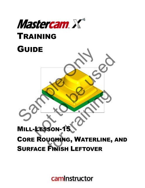
MILL-LESSON-15<br />
not to be used<br />
CORE ROUGHING, WATERLINE, AND<br />
for training<br />
SURFACE FINISH LEFTOVER
Mastercam Training Guide<br />
Objectives<br />
You will use a provided model for Mill-Lesson-15, then generate the toolpaths to machine the<br />
part on a CNC vertical milling machine. This Lesson covers the following topics:<br />
Establish Stock Setup settings:<br />
�<br />
Stock size using Bounding Box.<br />
Material for the part.<br />
Feed calculation.<br />
Generate 3-dimensional milling toolpaths consisting of:<br />
�<br />
Core Roughing<br />
Waterline<br />
Surface Finish Leftover<br />
Inspect the toolpath using Mastercam’s Verify by:<br />
�<br />
Launching the Verify function to machine the part on the screen.<br />
Comparing a verified part to the original stock stl file.<br />
Generating the NC- code.<br />
Sample Only<br />
not to be used<br />
for training<br />
Mill-Lesson-15 - 1
TOOL LIST<br />
1.000 diameter flat end mill to rough and finish machine.<br />
�<br />
.500 diameter ballnose to finish machine<br />
�<br />
.125 diameter ballnose to finish machine<br />
�<br />
.0313 diameter ballnose to finish machine<br />
�<br />
Sample Only<br />
Mill-Lesson-15 - 2<br />
Mill-Lesson-15<br />
not to be used<br />
for training
Mastercam Training Guide<br />
MILL-LESSON-15 - THE PROCESS<br />
<strong>Toolpath</strong> <strong>Creation</strong><br />
TASK 1: Setting the environment<br />
TASK 2: Open existing file from the multimedia CD<br />
TASK 3: Define the rough stock using stock setup<br />
TASK 4: Rough mold core using Surface High Speed (Core Roughing)<br />
TASK 5: Finish profile surfaces using Surface High Speed (Waterline)<br />
TASK 6: Finish all remaining stock using Surface Finish Leftover<br />
TASK 7: Verify the toolpath and compare to STL file<br />
TASK 8: Save the updated MCX file<br />
TASK 9: Post and create the CNC code file<br />
TASK 10: Create ActiveReport<br />
Sample Only<br />
not to be used<br />
for training<br />
Mill-Lesson-15 - 3
Mill-Lesson-15 - 4<br />
Mill-Lesson-15<br />
TASK 1:<br />
SETTING THE ENVIRONMENT<br />
Before starting the geometry creation you should set up the grid, toolbars and machine type as<br />
outlined in the Setting the environment section at the beginning of this text:<br />
1. Set up the Grid. This will help identify the location of the origin.<br />
2. Customize the toolbars to machine a 3D part.<br />
3. Set the machine type to a Haas Vertical Spindle CNC machine.<br />
<strong>Toolpath</strong> <strong>Creation</strong><br />
TASK 2:<br />
OPEN EXISTING FILE FROM THE MULTIMEDIA CD<br />
� On the multimedia CD that came with this text is a folder called Mastercam-Files. The file<br />
is in inch units and contains the wireframe and surface (solid) geometry of the part.<br />
� The part is already setup for a: GENERIC HAAS 4 – AXIS VMC.<br />
1. Select File>Open> Mill-Lesson-15.MCX.<br />
2. If confronted with the System Configuration dialog box activate the radio button for All<br />
settings.<br />
Sample Only<br />
System Configuration (switch units) dialog box<br />
�<br />
When you open a part file that uses different units (English or metric) from those currently in<br />
�<br />
use, Mastercam automatically displays this dialog box, which informs you that Mastercam is<br />
switching units and loading an alternate default configuration file. In order to complete the<br />
operation, select one of the following options:<br />
Units: Tells Mastercam to use only the units from the new configuration file. (default)<br />
�<br />
All settings: Tells Mastercam to load all settings from the new configuration file.<br />
�<br />
3. Select the OK button to exit the System Configuration dialog box.<br />
4. Activate a shaded view by selecting the icon at the top of the screen.<br />
not to be used<br />
for training
Mastercam Training Guide<br />
TASK 3:<br />
DEFINE THE ROUGH STOCK USING STOCK SETUP<br />
1. Click on the <strong>Toolpath</strong>s Tab as shown below: Note; Alt-O will Show/hide the Operations<br />
Manager pane.<br />
2. Select the + in front of Properties to expand the <strong>Toolpath</strong>s Group Properties. Select Stock<br />
setup in the toolpath manager window. Select the Bounding box button:<br />
3. Set the parameters to match the Bounding Box screenshot in the left image below, then<br />
select the OK button .<br />
Sample Only<br />
not to be used<br />
for training<br />
4. Set the parameters to match the Stock Setup screenshot shown in the above right image.<br />
Since the expand option in the bounding box window increased the size of the stock in both<br />
the negative and positive directions, the Z dimension needs to be reduced by 0.1. Simply<br />
select the Z dimension and add – 0.1 and hit enter.<br />
Mill-Lesson-15 - 5
Mill-Lesson-15 - 6<br />
Mill-Lesson-15<br />
5. Select the Tool Settings tab and change the parameters to match the Tool Settings<br />
screenshot below. Note: The Feed Calculation is set to From material. To change the<br />
Material type follow the instructions below:<br />
To change the Material type to Aluminium<br />
6061 pick the Select button at the bottom of<br />
the Tool Settings page.<br />
At the Material List dialog box open the<br />
Source drop down list and select Mill –<br />
library.<br />
From the Default Materials list select<br />
ALUMINIUM inch - 6061 and then select the<br />
OK button .<br />
6. Select the Edit button to enter the material definition. At this time we will not make any<br />
changes to Mastercam’s defaults, but it is important to know how this function works.<br />
Sample Only<br />
not to be used<br />
for training
Mastercam Training Guide<br />
Material Definition allows the user to enter the Base cutting speed (Surface Feet per Minute)<br />
and Base feed per tooth/revolution (Chip Load). These base values can be arrived at based<br />
on the material used. Mastercam’s default values are very conservative so we will use them for<br />
safety purposes during this tutorial.<br />
% of Base by Operation Type allows the user to specify a variation in SFM based on the<br />
operation type. Eg, face milling will have a much higher SFM than profile milling.<br />
% of Base by Tool Type allows the user to vary feed per tooth by the tool. Eg. endmills will<br />
typically have a much higher feed per tooth (FPT) than a ballnose tool will.<br />
Allowable tool materials and additional speed/feed percentages allows the user to further<br />
customize based on the tool type.<br />
The user can further adjust SFM and chip load percentages in each tool definition. This is<br />
demonstrated during the first operation in TASK 3.<br />
If cutting on a machine, it is extremely important that you research recommended SFM and FPT<br />
for your tools and material and make the appropriate settings in Mastercam.<br />
7. Select the OK button again to complete this function.<br />
8. Select the OK button again to exit the Machine Group Properties.<br />
9. Now select the Fit to screen icon then select the Isometric View icon.<br />
Your part should look similar to the screen shot below: With X0 Y0 at the center and Z zero<br />
�<br />
on the top of the stock.<br />
Sample Only<br />
not to be used<br />
for training<br />
Mill-Lesson-15 - 7
Mill-Lesson-15 - 8<br />
Mill-Lesson-15<br />
TASK 4:<br />
ROUGH OUT MOLD CORE USING SURFACE HIGH SPEED (CORE<br />
ROUGHING) TOOLPATH<br />
� In this task you will use a 1.000 diameter end mill to rough the part.<br />
1. From the bottom Status menu bar open the Level Manager and ensure level 1 and level 2<br />
are turned on.<br />
2. From the menu bar select <strong>Toolpath</strong>s>Surface High Speed…<br />
3. If prompted with the New 3D Advanced <strong>Toolpath</strong> Refinement Feature window, select<br />
Yes, I want to activate. Show me this dialog again.<br />
4. When prompted to Enter new NC name ensure Mill-LESSON-15 is visible and then select<br />
the OK button .<br />
5. You are first prompted to Select Drive surfaces, window select all of the entities on the<br />
screen.<br />
6. Click the End Selection icon .<br />
7. Click on the Containment Button.<br />
8. Select C-plane in the Chaining window as shown in the left image below. Then select the<br />
chain around the top of the mold base as shown in the right image below:<br />
Sample Only<br />
not to be used<br />
for training
Mastercam Training Guide<br />
9. Click on OK to exit Chaining and then confirm the number of drive surfaces as<br />
shown below:<br />
10. Click the OK button to enter the toolpath parameters.<br />
11. Select the <strong>Toolpath</strong> Type tab and activate the Roughing radio button, and then select the<br />
Core Roughing toolpath.<br />
12. Next, select the Tool tab. In the lower left corner of the page select the Select library<br />
tool… button.<br />
13. Select the Filter button and then select None. Now select only the Endmill1 Flat icon:<br />
Sample Only<br />
not to be used<br />
for training<br />
14. Select the OK button to exit the Tool List Filter.<br />
15. Use the scroll bar on the right of this dialog box to locate and select the 1 Inch Flat Endmill.<br />
16. Select the OK button to complete the selection of this tool.<br />
Mill-Lesson-15 - 9
17. Make changes to the Tool parameters page as shown below:<br />
Mill-Lesson-15 - 10<br />
Mill-Lesson-15<br />
By clicking on the<br />
tool on this page,<br />
you will<br />
automatically load<br />
the values for<br />
FPT (feed per<br />
tooth) and SFM<br />
(surface feet per<br />
minute). This is<br />
because we<br />
selected From<br />
Material on the<br />
Tool Settings tab<br />
of the Machine<br />
Group<br />
Properties.<br />
18. Right Click on the tool, select Edit Tool. Then go to the Parameters tab.<br />
% of matl cutting speed allows the user a<br />
further adjustment of SFM based on the<br />
particular tool.<br />
Sample Only<br />
19. Click the OK button to return to the Tool Parameters page.<br />
% of matl feed per tooth allows the user a<br />
further adjustment of FPT based on the particular<br />
tool.<br />
Refer to TASK 2 for material library information.<br />
not to be used<br />
for training
Mastercam Training Guide<br />
20. Make the selections shown below on the Cut Parameters page:<br />
21. Move to the Transitions page and make the following selections:<br />
Sample Only<br />
not to be used<br />
for training<br />
Mill-Lesson-15 - 11
Mill-Lesson-15 - 12<br />
Mill-Lesson-15<br />
22. On the Steep/Shallow page set the Minimum Depth of the cut to 0.1 (this is the top of<br />
stock). Right click in the Maximum Depth then select Z = Z coordinate of a point.<br />
23. Select the Z at the top of the mold base as shown below:<br />
Sample Only<br />
24. The resulting Steep/Shallow page values should match the following image:<br />
not to be used<br />
for training
Mastercam Training Guide<br />
25. Make the following selections on the Linking Parameters page: Open up the top drop down<br />
menu first and select Minimum Distance.<br />
26. Go to the Arc Filter/Tolerance page and make the following selections:<br />
Profile Tolerance must always be<br />
set at least as tight as the stock to<br />
leave value.<br />
Sample Only<br />
Mill-Lesson-15 - 13<br />
For the purposes of this tutorial we<br />
will do all roughing at .005 overall<br />
tolerance to speed calculation<br />
times.<br />
not to be used<br />
If cutting on a CNC machine, typical tolerance selections would range from .001 to .0001.<br />
for training
27. Select the Refine <strong>Toolpath</strong> button and make the following selections:<br />
28. Select the OK button to exit the Refine <strong>Toolpath</strong> window.<br />
29. Finally, move to the Coolant tab and turn Flood coolant on.<br />
30. Select the OK button to complete the toolpath.<br />
31. Verify the new toolpath.<br />
Sample Only<br />
Mill-Lesson-15 - 14<br />
Mill-Lesson-15<br />
not to be used<br />
for training
Mastercam Training Guide<br />
TASK 5:<br />
FINISH PROFILE SURFACES USING SURFACE HIGH SPEED<br />
(WATERLINE)<br />
Next you will finish the flat portions of the part using the Surface High Speed (Waterline)<br />
�<br />
toolpath.<br />
You may find it useful to toggle the display of toolpaths on and off during this lesson. Do<br />
�<br />
this by selecting Alt-T on your keyboard to hide/show the toolpath display.<br />
For programming, it is efficient to use Mastercam’s various functions such as Horizontal,<br />
Waterline and Rest Material to isolate part features and machine them with the best strategy<br />
and tools.<br />
Waterline toolpaths are best suited for surfaces whose angles are between 30 and 90 degrees.<br />
This is because the distance between passes is measured along the tool axis. Where the<br />
surfaces are shallower, material typically won't be removed as efficiently. However, you can<br />
configure the toolpath to generate extra cuts in shallow or flat areas.<br />
1. In the Operations Manager confirm that the red arrow used to locate new operations is in<br />
the Finishing <strong>Toolpath</strong> Group, just after the first operation. If it is not, simply grab it with<br />
the left mouse button, and drag it to the desired location.<br />
2. Create a new operation, by right clicking in the Operations Manager window, select Mill<br />
toolpaths>Surface high speed toolpath....<br />
3. Window select all elements on the screen when prompted to Select Drive Surfaces and<br />
click on End Selection .<br />
4. Select the Check Surfaces button and select the base solid as shown below. Solid<br />
Selection turned on.<br />
Sample Only<br />
5. Click on End Selection .<br />
not to be used<br />
for training<br />
Mill-Lesson-15 - 15
Mill-Lesson-15 - 16<br />
Mill-Lesson-15<br />
6. Now select the Containment button and select C-plane in the Chaining window. Next add<br />
the top edge of the mold base as the Containment Boundary.<br />
7. Select the OK button to exit Chaining and select the OK button to exit<br />
<strong>Toolpath</strong>/surface selection.<br />
8. Change the <strong>Toolpath</strong> Type to Finishing and select Waterline.<br />
Sample Only<br />
not to be used<br />
for training
Mastercam Training Guide<br />
9. Navigate to the Tool page and use the Select Library tool... icon to select a 0.500 Ball<br />
Endmill.<br />
10. Make the appropriate selections on the Cut Parameters page shown below. Note that the<br />
Stock to leave for all finishing toolpaths will be 0:<br />
Sample Only<br />
not to be used<br />
for training<br />
Mill-Lesson-15 - 17
11. Set the Transitions parameters as shown below:<br />
Mill-Lesson-15 - 18<br />
Mill-Lesson-15<br />
12. Select Steep/Shallow and select the Detect limits button to fill in the Minimum and<br />
Maximum depth:<br />
Sample Only<br />
not to be used<br />
for training
Mastercam Training Guide<br />
13. Set the Linking Parameters as shown below:<br />
14. Set the Arc Filter/Tolerance values as shown below:<br />
Sample Only<br />
not to be used<br />
for training<br />
15. Navigate to the Coolant tab and turn the Flood coolant on.<br />
16. Select the OK button to complete the toolpath.<br />
Mill-Lesson-15 - 19
17. Review Operation 2 using Backplot. The results are shown below:<br />
Sample Only<br />
Mill-Lesson-15 - 20<br />
Mill-Lesson-15<br />
not to be used<br />
for training
Mastercam Training Guide<br />
TASK 6:<br />
FINISH ALL REMAINING STOCK USING SURFACE FINISH LEFTOVER<br />
� Next you will finish leftover stock with a 0.125” ballnose tool.<br />
Great care must be taken to run the next toolpath on a machine. The toolpath uses a very small<br />
ballnose tool which is difficult to setup and machine due to tool length, rigidity, and strength.<br />
1. Select <strong>Toolpath</strong>s>Surface Finish>Leftover.<br />
2. Select the mold core solid on level 1 as the drive surface, leaving the base unselected.<br />
3. Click on End Selection .<br />
4. Select the Check select button and add the lower mold base solid on level 1 as a check<br />
surface.<br />
5. Click on End Selection .<br />
6. Select the OK button to continue.<br />
7. Select a 1/8 Ball Endmill from the tool library and turn on the Flood coolant on.<br />
Sample Only<br />
not to be used<br />
for training<br />
Mill-Lesson-15 - 21
8. Make the selections indicated on Surface parameters page shown below:<br />
Mill-Lesson-15 - 22<br />
Mill-Lesson-15<br />
9. Select the Finish Leftover Parameters tab and adjust the parameters as shown below:<br />
Sample Only<br />
not to be used<br />
for training
Mastercam Training Guide<br />
10. Select the Leftover Material Parameters tab and set the parameters as shown below:<br />
Similar to the Surface High<br />
Speed toolpaths this tab is<br />
used as a rough way of<br />
determining the stock left for<br />
machining.<br />
Mill-Lesson-15 - 23<br />
The Overlap distance is used<br />
to calculate the stock based<br />
on a larger tool size to make<br />
the computed stock to<br />
machine increase.<br />
11. Select OK to create the toolpath then Backplot after generation is complete. The<br />
results are shown below. If a warning dialog box appears select the OK to exit.<br />
Sample Only<br />
not to be used<br />
Typically a final toolpath would be required to finish the smallest fillets. The process would<br />
�<br />
require a smaller tool, and processing the toolpath with a tighter tolerance to get the desired<br />
results. As processing time will be high, please view the creation of this next toolpath as an<br />
optional exercise.<br />
for training<br />
12. Copy the last toolpath, Operation 3, and paste it below in the Operations Manager creating<br />
Operation 4.<br />
13. Select the Parameters option for Operation 4.<br />
14. Change the tool to a 1/32 Ball Endmill.
15. Adjust the surface Finish Leftover parameters page as shown below:<br />
Mill-Lesson-15 - 24<br />
Mill-Lesson-15<br />
16. Setup the Leftover material parameters to reflect the size of the previous tool used:<br />
Sample Only<br />
not to be used<br />
17. Select OK to exit the <strong>Toolpath</strong> Parameters.<br />
for training
Mastercam Training Guide<br />
18. Regenerate the toolpath by clicking on the Regenerate all dirty operations and Backplot<br />
the operation: If a warning dialog box appears select the OK to exit.<br />
Sample Only<br />
not to be used<br />
for training<br />
Mill-Lesson-15 - 25
TASK 7:<br />
VERIFY THE TOOLPATH AND COMPARE TO STL FILE<br />
Mill-Lesson-15 - 26<br />
Mill-Lesson-15<br />
Using Mastercam’s Compare to STL file function will allow us to identify areas on the part that<br />
require further machining as well as areas that may have been gouged. It is important to keep<br />
in mind that tolerances play a very large role in the use of this function. Accuracy of a<br />
comparison can only be as accurate as your machining tolerance.<br />
1. Use the Alt+Z shortcut to get to the Level Manager, turn on level 1, make all other levels<br />
invisible, exit the manager.<br />
2. In the top menu bar, select File>Save Some. You will be prompted to Select entities to<br />
save. Select the two solids (the main part and the base).<br />
3. Click on End Selection .<br />
4. The Save As dialogue box will open. Browse to your Mastercam install directory, then the<br />
data sub directory.<br />
5. For Save as type select .STL file then save the file with the name MILL-LESSON-15.STL.<br />
Sample Only<br />
6. Select the Options button and make the selections below.<br />
7. Select OK to exit Options.<br />
8. Select OK to exit Save As<br />
not to be used<br />
for training<br />
9. Select all of the operations you have completed so far by picking the Select All icon .
Mastercam Training Guide<br />
10. Select the Verify selected operations button circled below:<br />
11. Select the Turbo button. Turbo does not display the tool or holder and does not perform live<br />
updates of the stock, which is updated at the end of the verification. Turbo is generally the<br />
fastest option for verification.<br />
12. Check mark Stop on collision and set values as shown below:<br />
Sample Only<br />
not to be used<br />
for training<br />
Mill-Lesson-15 - 27
13. Select the Options button then make the following selections:<br />
Mill-Lesson-15 - 28<br />
Mill-Lesson-15<br />
14. Accept the selections by pressing the OK button then select the machine button to<br />
verify the toolpath. The verified part is shown below:<br />
Sample Only<br />
not to be used<br />
for training
Mastercam Training Guide<br />
15. The STL Compare dialogue box is now open. Select the File button and select the<br />
.stl file that you saved in the earlier step.<br />
16. The comparison stock model is now loaded. Select the Compare the machined stock<br />
and the STL file. The computed results are shown below:<br />
Compare the colours on the model with those on the chart at the left.<br />
Sample Only<br />
The light to dark blue shaded areas indicate additional stock to remove.<br />
The finishing tolerance was .001 so anything between light blue and yellow will be acceptable<br />
and considered complete.<br />
not to be used<br />
Purple to red shaded areas would indicate part gouges and areas in previous toolpaths that<br />
need to be addressed!<br />
17. Exit the STL Compare and Verify functions by clicking on the OK button .<br />
TASK 8:<br />
SAVE THE UPDATED MCX FILE<br />
10. Select the save icon from the toolbar .<br />
for training<br />
Mill-Lesson-15 - 29
TASK 9:<br />
POST AND CREATE THE CNC CODE FILE<br />
Mill-Lesson-15 - 30<br />
Mill-Lesson-15<br />
1. Ensure all the operations are selected by picking the Select All icon from the <strong>Toolpath</strong><br />
manager.<br />
2. Select the Post selected operations button from the <strong>Toolpath</strong> manager.<br />
Please Note: If you cannot see G1 click on the right pane of the <strong>Toolpath</strong> manger window and<br />
expand the window to the right.<br />
3. In the Post processing window, make the necessary changes as shown below:<br />
Sample Only<br />
4. Select the OK button to continue.<br />
5. Enter the same name as your Mastercam part file name in the NC File name field Mill-<br />
Lesson-15.<br />
6. Select the Save button.<br />
7. The CNC code file opens up in the default editor.<br />
not to be used<br />
for training<br />
8. Select the in the top right corner to exit the CNC editor
Mastercam Training Guide<br />
TASK 10:<br />
CREATE ACTIVEREPORT<br />
� Finally, you will create a report to help with part setup at the machine.<br />
1. In the top menu bar, select Settings>Configuration><strong>Toolpath</strong>s then change the Setup<br />
Sheet program to ActiveReport.<br />
2. Select the OK button to exit.<br />
3. Setup the screen so level 1 is the main and no other levels are visible. Exit the Level<br />
Manager and shade the solid.<br />
4. Right click inside the Operations Manager window and select Setup Sheet....<br />
5. Select the OK button to generate the report.<br />
6. The ActiveReports Viewer will load automatically. Note it may take a while to load.<br />
7. Print the report and go through the various pages comparing the report information to the<br />
toolpaths in the Operations Manager.<br />
8. You have the option of saving the report as any of the following file formats.<br />
Sample Only<br />
This completes Mill-Lesson-15.<br />
not to be used<br />
for training<br />
Mill-Lesson-15 - 31
MILL–LESSON-15 EXERCISE<br />
Mill-Lesson-15 - 32<br />
Mill-Lesson-15<br />
� The Mill-Lesson-15-Exercise file can be found on the accompanying DVD in the<br />
Mastercam-Files folder and is called Mill-Lesson-15-Exercise.mcx.<br />
Use the information learned in Lesson 15 to create a toolpath for the Mill-Lesson-15-Exercise.<br />
Sample Only<br />
not to be used<br />
for training