Mastercam Wire Lesson 2 - CamInstructor
Mastercam Wire Lesson 2 - CamInstructor
Mastercam Wire Lesson 2 - CamInstructor

Create successful ePaper yourself
Turn your PDF publications into a flip-book with our unique Google optimized e-Paper software.
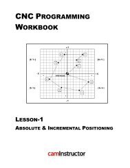
TEST PROJECT<br />
TEACHER GUIDELINES
<strong>Mastercam</strong> Intro to CAD/CAM<br />
Objectives<br />
You will create the geometry for Pen Base & Acylic Plaque, and then generate a toolpath to<br />
machine the part on a CNC machine. This projecct covers the following topics:<br />
� Create a 2-dimensional drawing by:<br />
Creating a Rectangle<br />
Creating Arcs<br />
Creating Lines<br />
Creating <strong>Mastercam</strong> geometry by converting an image file<br />
� Establish Stock Setup settings:<br />
Stock size<br />
Material for the part<br />
Feed calculation<br />
� Generate a 2-dimensional milling toolpath consisting of:<br />
Drill toolpath<br />
Pocket toolpath<br />
Contour toolpath<br />
� Inspect the toolpath using <strong>Mastercam</strong>’s Verify and Backplot by:<br />
Launching the Verify function to machine the part on the screen<br />
Using Backplot to identify the correctness of the toolpaths<br />
Generating the NC - code<br />
� Machine the parts consisting of:<br />
Machine a pen base<br />
Machine an acylic plaque<br />
Test Project Teacher Guidelines - 1
PEN BASE DRAWING<br />
Test Project Teacher Guidelines - 2<br />
Test Project
<strong>Mastercam</strong> Intro to CAD/CAM<br />
ACRYLIC PLAQUE DRAWING<br />
Test Project Teacher Guidelines - 3
PEN SET PROJECT - THE PROCESS<br />
PEN SET BASE<br />
Geometry Creation<br />
TASK 1: Setting the environment<br />
TASK 2: Create Geometry<br />
TASK 3: Save the drawing<br />
Toolpath Creation<br />
TASK 4: Define the Stock using Stock Setup<br />
TASK 5: Pocket Toolpath<br />
TASK 6: Drill Toolpath<br />
TASK 7: Backplot the Toolpath<br />
TASK 8: Verify the Toolpath<br />
TASK 9: Save the Updated MCX File<br />
TASK 10: Post and Create the CNC Code File<br />
ACRYLIC PLAQUE<br />
Geometry Creation<br />
TASK 1: Setting the environment<br />
TASK 2: Create Geometry<br />
TASK 3: Save the drawing<br />
Toolpath Creation<br />
TASK 4: Define the Stock using Stock Setup<br />
TASK 5: Contour Toolpath<br />
TASK 6: Backplot the Toolpath<br />
TASK 7: Verify the Toolpath<br />
TASK 8: Save the Updated MCX File<br />
TASK 9: Post and Create the CNC Code File<br />
Test Project Teacher Guidelines - 4<br />
Test Project
<strong>Mastercam</strong> Intro to CAD/CAM<br />
PEN SET BASE<br />
Geometry Creation<br />
TASK 1:<br />
SETTING THE ENVIRONMENT<br />
Before starting the geometry creation you should set up the grid, toolbars and machine type Set<br />
up the Grid. This will help identify the location of the origin.<br />
1. Customize the toolbars to machine a 2D part.<br />
2. Set the machine.<br />
TASK 2:<br />
CREATE GEOMETRY<br />
� X0 Y0 is top left hand corner of the part.<br />
TASK 3:<br />
SAVE THE DRAWING<br />
� File>Save<br />
Test Project Teacher Guidelines - 5
Toolpath Creation<br />
TASK 4:<br />
DEFINING THE ROUGH STOCK USING STOCK SETUP<br />
1. Change the parameters to match the Stock Setup screenshot below left:<br />
2. Click on Tool Settings and set the following.<br />
Test Project Teacher Guidelines - 6<br />
Test Project
<strong>Mastercam</strong> Intro to CAD/CAM<br />
TASK 5:<br />
POCKET TOOLPATH<br />
1. Change the graphics view to a Top View by using the toolbar at the top of the screen.<br />
2. From the menu bar select Toolpaths>Pocket Toolpath…<br />
3. If prompted to Enter new NC name ensure PEN is displayed and then select the OK button<br />
otherwise move on the step 4.<br />
4. On the screen, you will now see the Chaining dialog box and a screen prompt to Select<br />
pocket chain 1. Select two lines as shown below right. The green arrow is pointing to the<br />
left in a counter clockwise direction, climb milling. If the arrow is not pointing to the left,<br />
reverse the direction.<br />
Test Project Teacher Guidelines - 7
5. Make changes to the Toolpath parameters page as shown below.<br />
Test Project<br />
6. Select Pocketing parameters page and make changes to this page as shown below.<br />
7. Select Roughing/Finishing parameters page and make changes as shown below.<br />
Test Project Teacher Guidelines - 8
<strong>Mastercam</strong> Intro to CAD/CAM<br />
TASK 6:<br />
DRILL TOOLPATH<br />
1. Select from the pull down menu Toolpaths>Drill Toolpath...<br />
2. Select the point you wish to drill.<br />
3. Change the Toolpath parameters as shown below.<br />
4. Click on Simple drill-no peck and make changes as shown below.<br />
5. Select the OK button<br />
Test Project Teacher Guidelines - 9
TASK 7:<br />
BACKPLOT THE TOOLPATH<br />
TASK 8:<br />
VERIFY THE TOOLPATH<br />
TASK 9:<br />
SAVE THE UPDATED MCX FILE<br />
TASK 10:<br />
POST AND CREATE THE CNC CODE FILE<br />
1. Pick the Select All icon from the Toolpath manager.<br />
Test Project<br />
2. Select the Post selected operations button from the Toolpath manager.<br />
� Please Note: If you cannot see G1 click on the right pane of the Toolpath manger window<br />
and expand the window to the right.<br />
3. In the Post processing window, make the necessary changes as shown below:<br />
4. Select the OK button to continue.<br />
5. Ensure the same name as your <strong>Mastercam</strong> part file name is displayed in the NC File name<br />
field as shown below:<br />
Test Project Teacher Guidelines - 10
<strong>Mastercam</strong> Intro to CAD/CAM<br />
6. Select the Save button .<br />
7. The CNC code file opens up in the default editor.<br />
8. Select the in the top right corner to exit the CNC editor.<br />
9. This completes the Pen Set Base.<br />
Test Project Teacher Guidelines - 11
ACRYLIC PLAQUE<br />
Geometry Creation<br />
Test Project<br />
TASK 1:<br />
SETTING THE ENVIRONMENT<br />
Before starting the geometry creation you should set up the grid, toolbars and machine type Set<br />
up the Grid. This will help identify the location of the origin.<br />
1. Customize the toolbars to machine a 2D part.<br />
2. Set the machine type.<br />
TASK 2:<br />
CREATE GEOMETRY<br />
1. Select from the pull down menu Art>Trace Image-Ras2Vec… Note: If Trace Image-<br />
Ras2Vec is greyed out, click on Start Art from the bottom of the menu bar.<br />
2. A window may appear asking to Merge Geometry; Yes No, click on Yes.<br />
3. The Open window appears. Locate the file.jpg file and click on Open as shown below:<br />
Test Project Teacher Guidelines - 12
<strong>Mastercam</strong> Intro to CAD/CAM<br />
4. The Black/White conversion window appears. Drag the Threshold bar to the right until<br />
you get the image on the right pane. Notice the image gets darker. Click on OK .<br />
� Linear Black/White conversion: Converts the RGB color of each pixel to a greyscale pixel.<br />
The Threshold bar filters out converted pixels according to their greyscale rate.<br />
� Filter colors: Filters desired colors from a graphic image for conversion. Click any color box<br />
to filter. Click the color box again to deselect. The Tolerance bar decides how intensely<br />
selected colors are filtered.<br />
Test Project Teacher Guidelines - 13
Test Project<br />
5. The Rast2Vec window appears. Click on the Resolution DPI: drop down box and select<br />
300 as shown below:<br />
6. Notice the picture size, (1) it reads 1.33” x 2.15”. Note: when you change the resolution<br />
the picture size will change as well.<br />
7. Make sure Create Outlines (2) is selected as shown below:<br />
8. Select Lines, corners and arcs from the Optimize for: drop down list (3).<br />
9. Click on OK .<br />
Test Project Teacher Guidelines - 14
<strong>Mastercam</strong> Intro to CAD/CAM<br />
10. The <strong>Mastercam</strong> Screen should look like the image below: The new image (1) will be<br />
displayed as geometry and the Smooth Geometry window (2) will be appear. Click on OK<br />
.<br />
11. Click on Yes when asked; “Would you really like to exit Rast2Vec?”<br />
3. Make changes as shown below.<br />
8. Using Xform, move or modify the geometry. Ensure X0 Y0 is top left hand<br />
corner of the part.<br />
Test Project Teacher Guidelines - 15
TASK 3:<br />
SAVE THE DRAWING<br />
� File>Save<br />
Toolpath Creation<br />
TASK 4:<br />
DEFINING THE ROUGH STOCK USING STOCK SETUP<br />
1. Change the parameters to match the Stock Setup screenshot below left:<br />
Test Project Teacher Guidelines - 16<br />
Test Project
<strong>Mastercam</strong> Intro to CAD/CAM<br />
2. Click on Tool Settings and set the following.<br />
Test Project Teacher Guidelines - 17
TASK 5:<br />
CONTOUR TOOLPATH<br />
Test Project<br />
1. Change the graphics view to a Top View by using the toolbar at the top of the screen.<br />
2. From the menu bar select Toolpaths>ContourToolpath…<br />
3. When prompted to Enter new NC name ensure PLAQUE is displayed and then select the<br />
OK button .<br />
4. On the screen, you will now see the Chaining dialog box and a screen prompt to Select<br />
pocket chain 1. Create a window as shown below by selecting the upper left corner at<br />
position 1 and dragging to the opposite lower right corner at position 2.<br />
Click<br />
5. You will be prompted to Sketch approximate start point, then click inside the window box<br />
as shown above.<br />
Test Project Teacher Guidelines - 18
<strong>Mastercam</strong> Intro to CAD/CAM<br />
6. Make changes to the Toolpath parameters page as shown below.<br />
7. Select Contour parameters page and make changes to this page as shown below.<br />
8. Select the OK button<br />
Test Project Teacher Guidelines - 19
TASK 6:<br />
BACKPLOT THE TOOLPATH<br />
TASK 7:<br />
VERIFY THE TOOLPATH<br />
TASK 8:<br />
SAVE THE UPDATED MCX FILE<br />
TASK 9: POST AND CREATE THE CNC CODE FILE<br />
1. Pick the Select All icon from the Toolpath manager.<br />
Test Project<br />
2. Select the Post selected operations button from the Toolpath manager.<br />
� Please Note: If you cannot see G1 click on the right pane of the Toolpath manger window<br />
and expand the window to the right.<br />
3. In the Post processing window, make the necessary changes as shown below:<br />
4. Select the OK button to continue.<br />
5. Ensure the same name as your <strong>Mastercam</strong> part file name is displayed in the NC File name<br />
field as shown below:<br />
Test Project Teacher Guidelines - 20
<strong>Mastercam</strong> Intro to CAD/CAM<br />
6. Select the Save button .<br />
7. The CNC code file opens up in the default editor.<br />
8. Select the in the top right corner to exit the CNC editor.<br />
9. This completes Acrylic Plaque.<br />
Test Project Teacher Guidelines - 21
Pen Set Base<br />
Check List<br />
Test Project<br />
No Items to be checked Check<br />
General<br />
1 Machine Type: Check with your instructor<br />
2 Program Number: 1<br />
3 Program Name: PEN-Yourname.MCX<br />
4 Location of X0 Y0 : Bottom left hand corner of material<br />
5 Z=0: Top of the part<br />
6 Stock Setup: Material size 6” x 3” x .5”<br />
7 Cutter: Ø.125 Endmill- Tool # 1 & Length offset #1<br />
Drilling<br />
8 Feedrate: 30 inches per minute<br />
Spindle speed: 4000 rpm / Coolant Off<br />
9 Depth of Hole: -0.6” in Absolute<br />
10<br />
Clearance:<br />
Retract:<br />
Top of Stock:<br />
2 in.<br />
0.1 in.<br />
0 (all in absolute)<br />
Pocketing<br />
11 Feedrate: 30 inches per minute<br />
12 Plunge feedrate: 10 inches per minute<br />
13 Spindle speed: 4000 rpm<br />
14 Pocket Depth: -.25” in Absolute<br />
15 Clearance: 2 in.<br />
16 Retract & Feed plane: 0.1 in. Top of Stock 0 (all in absolute)<br />
17 Pocket Cutting Method: Parallel Spiral ( NO FINISH)<br />
18 Check mark on: “Spiral Inside to Outside”<br />
Posting<br />
20 Save the CNC code file: on a diskette or an USB<br />
21 File Name: PEN-Yourname.NC<br />
Machine Part<br />
22 Prepare material for machining<br />
23 Fixture material onto Machine table<br />
24 Install proper cutter into Machine Spindle<br />
25 Set up Work and Tool Offsets on Machine<br />
26 Load proper NC file<br />
27 Machine part<br />
28 Deburr<br />
29 Clean machine and put tools back<br />
Test Project Teacher Guidelines - 22
<strong>Mastercam</strong> Intro to CAD/CAM<br />
4 x 4 Acrylic Plaque<br />
Check List<br />
No Items to be checked Check<br />
General<br />
1 Machine Type: Check with Instructor<br />
2 Program Number: #1<br />
3<br />
Location of X0 Y0: Bottom left hand corner of material (both geometry &<br />
stock)<br />
4 Z=0: is the top of the part<br />
5<br />
Stock Setup: Material size 4” x 4” x .25” (Material type doesn’t<br />
matter)<br />
6<br />
Cutter:<br />
Ø1/32 (Ø.03125 Endmill- Tool # 2 & Length offset #2)<br />
Contouring<br />
7 Feed Rate: 20 inches per minute<br />
8 Plunge Rate: 20 inches per minute<br />
9 Retract Rate: Rapid – Check mark for Rapid Retract<br />
10 Spindle Speed: 4000 rpm<br />
11 Depth of cut: -0.010” in Absolute<br />
12<br />
Clearance: 2.0 Check mark for “Clearance only at start and end of<br />
operation”<br />
13 Retract: 0.1 in Absolute<br />
14 Feed Plane: 0.1 in Absolute<br />
15 Top of Stock: 0 in Absolute<br />
17 Compensation Type:<br />
Posting<br />
OFF<br />
19 Save the CNC code file: on a diskette or an USB<br />
20 File Name:<br />
Machine Part<br />
PLAQUE-Yourname.NC<br />
1 Prepare material for machining<br />
2 Fixture material onto Machine table<br />
3 Install proper cutter into Machine Spindle<br />
4 Set up Work and Tool Offsets on Machine<br />
5 Load proper NC file<br />
6 Machine part<br />
7 Deburr<br />
8 Clean machine and put tools back<br />
Test Project Teacher Guidelines - 23