JBE Manual - Electromach BV
JBE Manual - Electromach BV
JBE Manual - Electromach BV

You also want an ePaper? Increase the reach of your titles
YUMPU automatically turns print PDFs into web optimized ePapers that Google loves.
<strong>Electromach</strong> member of the R.STAHL Technology Group<br />
OPERATING INSTRUCTIONS<br />
TERMINAL BOX<br />
<strong>JBE</strong> (ATEX)<br />
<strong>Electromach</strong> B.V.<br />
Jan Tinbergenstraat 193<br />
7559 SP Hengelo<br />
The Netherlands<br />
T +31 (0)74 2 472 472<br />
F +31 (0)74 2 435 925<br />
info@electromach.nl<br />
www.electromach.com<br />
Bank: ABN-AMRO 59.01.14.573<br />
IBAN: NL29ABNA0590114573<br />
BIC: ABNANL2A<br />
VAT/BTW: NL 003578458B01<br />
Bank: Fortis 24.35.24.439<br />
IBAN: NL67FTSB0243524439<br />
BIC: FTSBNL2RXXX<br />
KVK nr: 06040491<br />
Leveringen geschieden<br />
overeenkomstig de voorwaarden.<br />
Deliveries subject to general<br />
conditions of sale.
INDEX<br />
APPLICATION.................................................................................................................................................... 3<br />
PURPOSE OF THESE INSTRUCTIONS .......................................................................................................... 3<br />
1 SAFETY INSTRUCTIONS .............................................................................................................................. 4<br />
1.1 CONFORMITY TO STANDARDS ........................................................................................................... 5<br />
2 TECHNICAL DATA ......................................................................................................................................... 6<br />
2.1 EXPLOSION PROTECTION ................................................................................................................... 6<br />
2.2 FITTINGS IN TERMINAL BOX TYPES <strong>JBE</strong> ............................................................................................ 7<br />
3 DIMENSION SKETCH .................................................................................................................................... 8<br />
4 INSTALLATION .............................................................................................................................................. 9<br />
4.1 MAINS CONNECTION ............................................................................................................................. 9<br />
4.2 EARTH CONNECTION ............................................................................................................................ 9<br />
5 COMMISSIONING ......................................................................................................................................... 10<br />
6 REPAIRS AND MAINTENANCE ................................................................................................................. 11<br />
7 ACCESSORIES / SPARE ............................................................................................................................. 12<br />
8 DISPOSAL ..................................................................................................................................................... 12<br />
9 EC-TYPE EXAMINATION CERTIFICATE ................................................................................................... 13<br />
10 DECLARATION OF CONFORMITY .......................................................................................................... 16<br />
PAGE 2/ 16
APPLICATION<br />
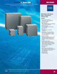
Terminal boxes type <strong>JBE</strong> is explosion-protected and suitable for fixed mounting. They distribute electrical<br />
energy in hazardous areas.<br />
They are manufactured from sheet or stainless steel in a range of sizes. They can be combined to provide<br />
more extensive distribution systems.<br />
PURPOSE OF THESE INSTRUCTIONS<br />
Working in hazardous areas, the safety of personnel and plant depends on complying with all relevant<br />
safety regulations.<br />
Assembly and maintenance staff working on installations therefore have a particular responsibility. They<br />
require precise knowledge of the applicable standards and regulations.<br />
These instructions give a brief summary of the most important safety measures. They supplement the<br />
corresponding regulations which the staff responsible must study.<br />
Subject to alteration.<br />
PAGE 3/ 16
1 SAFETY INSTRUCTIONS<br />
Use the terminal box only for its permitted purpose.<br />
Incorrect or impermissible use or non-compliance with these instructions invalidates our warranty<br />
provision.<br />
Any alterations and modifications to the box impairing its explosion protection are not permitted.<br />
Use the terminal box only if it is clean and undamaged.<br />
Observe the following during setting-up and operation:<br />
<br />
<br />
<br />
<br />
<br />
<br />
<br />
national safety regulations;<br />
national accident prevention regulations;<br />
national installation regulations;<br />
(e.g. IEC 60079-14)<br />
generally recognized technical regulations;<br />
safety guidelines in these operating instructions;<br />
characteristic values and rated operating conditions on the rating and data plates;<br />
additional instruction plates fixed directly to the device.<br />
Any damage can invalidate the Ex-protection.<br />
The inactive metal parts are insulated in accordance with EN 60439 Part 1 (IEC 60439-1) and are not<br />
linked to the earthing system (PE).<br />
If required, we will provide a copy of the EC Type-Test Certificate with the relevant annex.<br />
The fitting of additional terminals, isolating terminals, fuses or cables gland is only permitted<br />
when the individual components are certified to Directive 94/9/EC and thus, have an EC<br />
prototype test certificate. When carrying out this type of modification to the terminal box the<br />
type and data plates must be observed!<br />
PAGE 4/ 16
1.1 CONFORMITY TO STANDARDS<br />
Each box complies with the following standards and regulations:<br />
Directive 94/9/EC<br />
EN 50014, EN 50018, EN 50019,<br />
EN 50020, EN 50028<br />
EN 60947-1/A11<br />
EMC Directive No.: 89/336/EC<br />
Terminal boxes type <strong>JBE</strong> is suitable for use in hazardous areas zones 1, 2, 21 and 22.<br />
PAGE 5/ 16
2 TECHNICAL DATA<br />
2.1 EXPLOSION PROTECTION<br />
Test certificate: KEMA 02 ATEX 2272<br />
Material:<br />
Sheet or stainless steel<br />
a. fitted with terminals II 2G EEx e II bzw. / or / ou<br />
II 2G EEx e [ia] IIC T<br />
b. fitted with isolating terminals II 2G EEx ed IIC T bzw. or / ou<br />
II 2G EEx ed [ia] IIC T<br />
c. fitted with terminals and fuses II 2G EEx em II T bzw. /or / ou<br />
II 2G EEx em [ia] IIC T<br />
d. fitted with terminals, isolating terminals and fuses II 2G EEx edm IIC T bzw. /or / ou<br />
II 2G EEx edm [ia] IIC T<br />
Working temperature range:<br />
Standard<br />
Special<br />
- 20 C ... + 40 C<br />
- 20 C ... + 55 C<br />
Ambient temperature range for terminal boxes without<br />
fuses fitted<br />
T6: - 20 °C ... + 40 °C<br />
T5: - 20 °C ... + 55 °C<br />
If your application requires the ambient temperature range to be extended at the lower end, <strong>Electromach</strong><br />
can supply special designs.<br />
PAGE 6/ 16
When fitting fuses, the ambient temperature values for the following temperature classes<br />
apply:<br />
Fuse current value 4 A corresponds to T6<br />
4 A > fuse current value 5 A corresponds to T5<br />
5 A > fuse current value 6,3 A corresponds to T4<br />
Degree of protection to IEC/CEI 60529:<br />
max. IP 66<br />
Terminal box EEx e type <strong>JBE</strong><br />
Rated operating voltage<br />
Cross-section for connection<br />
max. 11 kV<br />
max. 300 mm²<br />
Terminal box EEx i type <strong>JBE</strong><br />
The electrical data depend on the rated operating<br />
values of the intrinsically safe circuits installed.<br />
The devices fitted to type <strong>JBE</strong> enclosures differ according to customers’ requirements.<br />
Please also observe the operating instructions for these.<br />
Please consult the manufacturer if there are other non-standard operating conditions.<br />
2.2 FITTINGS IN TERMINAL BOX TYPES <strong>JBE</strong><br />
See additional attachment<br />
PAGE 7/ 16
3 DIMENSION SKETCH<br />
When explosion-protected equipment is<br />
exposed to the weather, it is advisable to<br />
provide a protective cover or wall.<br />
1) WELDSTUDS M8x15 ON REARSIDE<br />
CAN BE USED FOR FRAMEMOUNTING.<br />
PAGE 8/ 16
4 INSTALLATION<br />
4.1 MAINS CONNECTION<br />
<br />
<br />
<br />
<br />
The conductors must be carefully connected.<br />
The conductor insulation must reach to the terminal. The conductor itself must not be damaged<br />
(nicked) when removing the insulation.<br />
Ensure that the maximum permissible conductor temperatures are not exceeded by suitable<br />
selection of cables and means of running them.<br />
Please also refer to the terminal details in the technical data.<br />
4.2 EARTH CONNECTION<br />
The earth connection must be made in all circumstances.<br />
The external earth connection accepts a cable lug. The cable must be run and fixed near to the enclosure<br />
to prevent movement of the cable.<br />
PAGE 9/ 16
5 COMMISSIONING<br />
Before commissioning device, ensure that<br />
<br />
<br />
<br />
<br />
<br />
<br />
<br />
<br />
<br />
it has been correctly installed;<br />
it is not damaged;<br />
it contains no foreign bodies;<br />
the connection chamber is clean;<br />
the connection is correctly made;<br />
the cables have been correctly brought in;<br />
all screws and nuts are fully tightened;<br />
the cable glands and stopping plugs are securely tightened;<br />
unused cable entries are sealed with plugs certified to Directive 94/9/EC, and unused holes are<br />
sealed by stopping plugs certified to Directive 94/9/EC.<br />
PAGE 10/ 16
6 REPAIRS AND MAINTENANCE<br />
Do not open the box when supply is on!<br />
Do not open when non-intrinsically safe circuits are energized!<br />
Exception: boxes with intrinsically and non-intrinsically safe circuits having the sign „Nonintrinsically<br />
safe circuits protected by IP30 guard“ may be opened when energized.<br />
Repairs and maintenance work on the devices may only be carried out by appropriately authorized and<br />
trained personnel. Before work commences the devices must be disconnected from the mains.<br />
Observe the relevant national regulations for your country!<br />
The following points must be tested during maintenance:<br />
clamping screw holding the cable is securely seated;<br />
compliance with permitted temperatures (to EN 50014);<br />
damage to the housing;<br />
<br />
damage to the gaskets.<br />
PAGE 11/ 16
7 ACCESSORIES / SPARE<br />
Use only original spare parts as well as original accessories.<br />
When fitting terminal blocks, please ensure that they comply with Directive 94/9/EC and<br />
have an EC-type test certificate.<br />
To avoid build-up of condensation in the metal box, we recommend the use of a breathing<br />
gland. However, when using this breathing gland it should be noted that, depending on the<br />
location of the box a reduction in the level of protection to IEC 60529 results.<br />
8 DISPOSAL<br />
Observe the national standards for refuse disposal.<br />
We are pleased to answer any special questions you may have.<br />
Should you require the operating instructions in one of the other European Community languages, please<br />
feel free to contact <strong>Electromach</strong>.<br />
PAGE 12/ 16
9 EC-TYPE EXAMINATION CERTIFICATE<br />
PAGE 13/ 16
PAGE 14/ 16
PAGE 15/ 16
10 DECLARATION OF CONFORMITY<br />
PAGE 16/ 16